
 ?Mathematical formulae have been encoded as MathML and are displayed in this HTML version using MathJax in order to improve their display. Uncheck the box to turn MathJax off. This feature requires Javascript. Click on a formula to zoom.
ABSTRACT
This paper proposes an enhanced primary control unit of the distributed generator inside the microgrid when the DG is grid-connected and when operated autonomously. The control methods needed for the DG inverter when operated in grid-connected mode and autonomous operation mode have been investigated. The rotating reference frame employed for the control of the DG has been clarified to investigate how the active and reactive power of the DG are delivered to the main grid. When the DG suffers from local disturbance conditions, it should be disconnected from the main grid and switched off or its control unit is changed to voltage-frequency mode. Therefore, a fault detection scheme has been implemented to monitor the voltage and frequency of the DG bus. Hence, the performance of the proposed work has been validated under steady-state and short circuit conditions where the DG inverter is operated in grid-connected mode, switch-off mode, and autonomous mode.
1. Introduction
The microgrid which is already defined as a local grid has the property that it combines multiple distributed generators (DGs) whatever about the energy source and local loads, plus energy storage systems. The DG inside the microgrid has the property that it can work autonomously or grid-connected depending on the network condition if either balanced or disturbed by short circuit conditions. A smooth transfer between both DG operation modes can be achieved through proper management in the DG control unit (Guerrero et al. Citation2013; Wu et al. Citation2014). Controlling the DG which is normally interfaced with a power electronic device is unlike the control of the generation source as its interface is simply an electric machine. Therefore, the insertion of DG sources within the distribution network will affect the overall power system performance (Krishan and Suhag Citation2019; Razmjoo et al. Citation2021).
The network can be more efficient and flexible if the microgrid is disconnected from the centralised network. Thus, splitting the network into small controllable systems. However, this will arise issues in the distribution network like protection coordination and voltage level. The increased DG penetration into the distribution network will increase the harmonic percentage due to the presence of power electronic inverters and the short circuit impedance will decrease too (Lu Citation2022; Vegunta et al. Citation2021).
The total control structure of the microgrid can be classified into three categories and each category has a defined goal. These categories are the primary control, the secondary control, and the tertiary control. The primary control is responsible for the voltage and current control as well as the power-sharing control. The secondary controller is responsible for power flow control and power quality, where the tertiary controller is responsible for the economic dispatching and optimisation, in addition to the microgrid supervision (Feng et al. Citation2017; Yamashita, Vechiu, and Gaubert Citation2020; Zhao et al. Citation2023). The DG control in this paper was focused on the primary controller as the others are out of the paper scope.
The primary controller is used as a local controller where it regulates the voltage reference needed for the internal current and voltage loops. This will ensure that the DG inverter local voltage is stable and the microgrid is operating in an optimal way. Also, once the reference voltage is regulated, the active and reactive power will be successfully delivered into the network. A lot of schemes have been proposed in the literature for the primary control of voltage source inverters, especially for those which are interfaced by distributed energy sources (Alfergani et al. Citation2018; Fusero et al. Citation2019; Khanbaghi and Zecevic Citation2022; Omar Citation2020; Rokrok, Shafie-khah, and Catalão Citation2018; Salem and Alzaareer Citation2021; Unamuno and Barrena Citation2016).
The DG inside the microgrid can be disconnected from the main grid and work autonomously once a grid disturbance is detected. In this case, the DG switch its control to the islanding mode of operation. This switching is essential to supply constant voltage to the local load. However, when the disturbance occurs on the DG side, either the inverter of the DG should be turned off or loading shedding should take place. Several research papers have investigated the grid-connected and islanded operation of DGs. Some have employed advanced techniques like modified droop controllers and others have investigated the stability and performance of the controller itself like the dynamic response of the controller (Guerrero et al. Citation2009; Hamidi et al. Citation2016; Haque, Negnevitsky, and Muttaqi Citation2010; Liu, Bevrani, and Ise Citation2022; Mehrasa et al. Citation2015; Monopoli and Ticali Citation2020; Yazdani, Ferdowsi, and Shamsi Citation2020). Furthermore, a review for the deep insight of different control methods applied at the secondary and primary control (droop and non-droop) for DGs in microgrids is covered in (Ahmed et al. Citation2021) and (Sahoo, Sinha, and Kishore Citation2018). Here, the control methods that are needed for the DG operation in grid-connected mode and the islanded (autonomous) mode are summarised. Although the primary and secondary controls including their various control methods are well known, a little number of research articles discuss the combination of two control methods for the DG based on a fault detection scheme (either passive or active). Also, no recent study investigates how the DG can be turned off once a fault is detected instead of switching the DG control to V/f mode. Thus, the novelty and contribution of this paper are summarised:
- Implementing control methods for the DG to work in grid-connected and islanded modes based on an enhanced fault detection scheme.
- Implementing an alternative method rather than the V/f control method for the DG to work in islanded (autonomous) mode.
In this paper, a grid-connected microgrid is proposed. The microgrid is represented by only one DG and local load. A fault detection scheme is implemented within the DG control unit to detect the presence of a fault where the voltage and frequency of the DG are monitored by over/under frequency and voltage relays. Once the fault is detected, a trip signal is sent to the inverter to turn off or to work in islanded/autonomous mode.
Following the introduction, section 2 presents the network formulation including the proposed network, the DG inverter and its control structure during the grid-connected, switch off, and autonomous mode. Besides, the fault detection scheme based on voltage and frequency measurements is investigated. The mathematical modelling of the DG in the rotating reference frame is presented in section 3. Section 4 presents the simulation results under various operating conditions, and section 5 presents the conclusion.
2. Network formulation
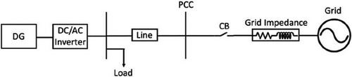
A model representation of the three-phase distributed generator (DG) with the main grid is presented in . Here, the microgrid is represented only on DG, the main grid is a low-voltage supply and
, the three-phase breaker is placed to disconnect the distributed generator from the main grid in case of short circuit conditions where the DG should either switch its control to the islanded mode or it can be turned off until the fault is cleared.
Figure 1. Model representation of the proposed network.
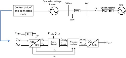
shows the subsystem which represents the DG and DC/AC inverter blocks. These blocks represent the three-phase inverter and its control structure. Here, the DG inverter is implemented as an ideal controlled voltage source. This inverter is controlled to operate in grid-connected mode under normal operating conditions. The control structure used in grid-connected mode is called PQ control which is implemented in synchronous reference (dq) farme. The voltage and current of the DG bus and
are measured and converted to DC quantities (
). Then, the real and reactive power references (
) are divided by the direct voltage
to extract the reference currents
and
which are compared with their measured values and passed through PI controllers to derive the reference voltages
and
. Those two voltages are then transformed from DQ to ABC to extract the reference voltage
of the controlled voltage source. The phase-locked loop (PLL) is used to synchronise the DG inverter frequency with the main grid frequency. Therefore, the measured voltage at PCC
is inserted into the PLL to extract
needed for the transformation from dq to abc or vice versa.
Figure 2. Three-phase inverter and its control structure.
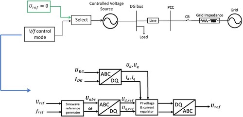
In case of abnormal conditions, the circuit breaker is opened after receiving a command signal from the fault detection scheme. Thus, a different control methodology is applied to the DG inverter where a reference voltage and frequency should be set as the main grid voltage and frequency are no more exist. This methodology is known as the V/f control mode or the autonomous mode where the DG switches its control to continue supplying the load with constant power. An alternative control method is to turn off the DG inverter and shed the load until the fault is cleared. This can be achieved by inserting a zero signal to the control unit as a reference voltage. Thus, the DG inverter provides zero real and reactive power and the load is dropped. The turn-off and V/f mode control of the three-phase inverter is shown in . In this method, an external supply is used to generate the reference voltage and frequency
as fixed values in the absence of the main grid. Then, a sinusoidal reference voltage and phase angle are generated and transformed into dq voltages (
) to be compared with their measured values. This will result in reference dq currents (
) which are again compared with their measured values and inserted to PI controllers to deliver the final voltage values. Finally, the reference voltage of the DG inverter
is extracted through the inverse transformation of the resultant voltages. If the selector selects
, the DG inverter will be turned off where no real and reactive power generation takes place and the load will be shed.
Figure 3. Turn-off mode and V/f control mode of the three-phase inverter.
The transfer between grid-connected mode and V/f mode is performed using a fault detection scheme which is installed at the control unit of the controlled voltage source to detect the presence of a fault. Once a fault is detected, the switch alters the control of the inverter from grid-connected mode to either the turn-off mode or the V/f control mode. In the turn-off mode, the DG is turned off until the fault is cleared. Once the fault is cleared, the DG can be turned on and works again in grid-connected mode. The fault detection scheme monitors the voltage and frequency of the DG where it takes the measurements from the DG bus shown in the proposed network.
The representation of the switch that selects the operation mode of the DG inverter as well as the fault detection scheme representation which is implemented based on a passive method is introduced in . In the fault detection scheme, a trip signal is generated to be sent to the switch block in order to alter the mode of operation from grid-connected mode to turning-off mode or to V/f control mode. The selection between the turn-off mode and the V/f mode is independent of the fault detection scheme operation. However, the selection between the grid-connected mode and the V/f mode depends mainly on the fault detection scheme. If the network did not suffer any disturbance, the DG inverter will work in grid-connected mode. However, if the network suffers from a short circuit, the fault detection scheme will detect this disturbance and will send a command signal to open the circuit breaker and switches the control mode to the V/f control mode.
Figure 4. Switch operation and fault detection scheme representation.
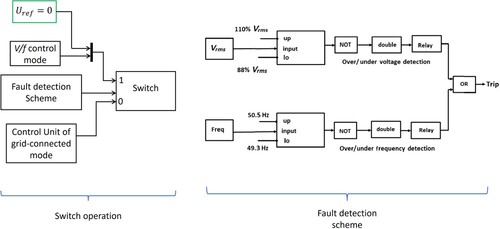
In the fault detection scheme, threshold values of voltage and frequency defined by an IEEE standard for interconnecting distributed resources with electric power systems are compared with the measured values from the DG bus. If the measured values are within the acceptable range, the inverter continues working in grid-connected mode. Otherwise, a trip signal is issued to switch the operation mode from grid-connected mode turn-off mode or V/f control mode. The permissible voltage and frequency range lies within and
, respectively. The relays used for detection are over/under frequency and voltage relays.
3. Mathematical modelling in rotating reference (dq) frame
The control unit of the DG for the grid-connected mode using the synchronous reference (dq) frame has two main loops: the power control loop and the current control loop. These loops require a phase angle reference to transform the abc voltages and currents into dq components. The transformation is done in two successive steps namely Clarke’s transformation and Park’s transformation.
Clarke’s transformation is the procedure for obtaining the (0) components from a three-phase variable. The forward and reverse transformations of three-phase (ABC) voltages and currents are provided by the following equations.
(1)
(1)
(2)
(2) Where, the factors
[K
], and
are given as,
(3)
(3)
(4)
(4)
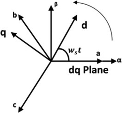
The rotating reference frame is shown in is a rotational frame that rotates at the same synchronous speed as the system. Park’s transformation method is used to derive the rotating reference frame’s transformation from the stationary reference frame. Direct (d), quadrature (q), and zero components are used to represent modified values in the rotating frame. The equations below describe the transformation from 0 frame to rotating reference frame.
(5)
(5)
(6)
(6)
Figure 5. Rotating reference frame.
Where, [Kdq0] is the transformation factor given by,
(7)
(7) By combining Clarke’s and Park’s transformations, direct transformation into dq0 from three-phase variables is obtained as:
(8)
(8)
Combining Kαβ0 and Kdq0 yields the transformation factor, which is presented below.
(9)
(9) The synchronous reference frame rotates at
angular frequency to provide constant values for the sinusoidally oscillating variables. The conversion from stationary to rotating synchronous reference is shown in the equation below:
(10)
(10)
As a result, the dq domain representation of voltage and current phasors may be written similarly to αβ domain and provided in the equations below:
(11)
(11)
(12)
(12)
Thus, the three-phase power in the dq frame can be calculated as:
(13)
(13) So the active and reactive power may be expressed as,
(14)
(14)
(15)
(15) The phase-locked loop is used to track the phase angle of the grid for synchronisation purposes where it generates the required phase angle reference for
transformation or vice versa.
4. Simulation results
The Simulink model of is executed considering three case scenarios: the first is when the DG operates under grid-connected mode and the second is when a fault occurs in the system and thus the inverter is turned off. The third one is when the DG switches its control mode to V/f control mode.
shows the resistance and inductance of the grid, DG, and line, and the load characteristics used in the model.
Table 1. Model parameters.
4.1. DG inverter under normal operating conditions
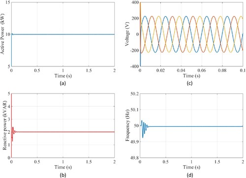
In this part, the system is assumed to be running in steady-state conditions where no disturbance condition is presumed. The grid-connected mode control unit is responsible for generating the real and reactive power references of the DG inverter. Here, the fault detection scheme takes no action as the voltage and frequency relays are not triggered. The DG is working under grid-connected mode where it delivers 10 kW and 2 kVAR. The load is assumed resistive, and it draws 5 kW. Thus, the rest 5 kW transfers to the main grid via the point of common coupling (PCC). The active/reactive power, voltage, and frequency of the DG under steady-state conditions are depicted in (a)–(d). It is clearly shown that the active and reactive powers are regulated to their references and the control unit in grid-connected mode is working properly in controlling both powers. It can also be noticed that the voltage and frequency are stable and have no oscillations.
Figure 6. Active/reactive power, voltage and frequency at the DG bus during normal operating conditions.
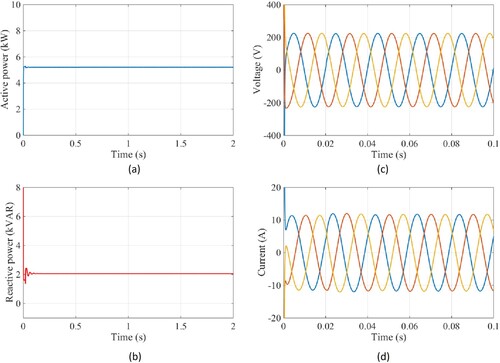
Furthermore, the active/reactive power, voltage, and current at PCC are depicted in (a–d). It is clearly shown that the rest of the active power (5 kW) is transferred to the main grid via the PCC. The reactive power appeared as 2 kVAR since the load is resistive. The voltage and current are also stable and within limits.
Figure 7. Active/reactive power, voltage and current at PCC during normal operating conditions.
4.2. DG inverter under switch-off mode
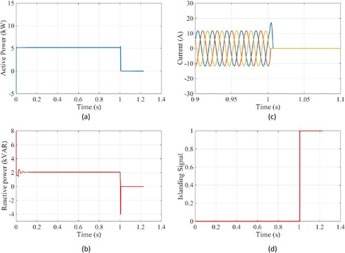
Here, a fault condition is assumed to occur at where the DG should switch off once the fault detection scheme detects the fault existence. The active and reactive power transfer to the main grid should be zero as the DG is turned off and disconnected from the main grid. (a–d) presents the active/reactive power, voltage, and frequency at the DG bus when a fault occurs at t = 1 s. The DG was working successfully before t = 1s. However, once the fault detection scheme detects the fault, the DG is turned off and active and reactive power reaches zero accordingly. Also, note that the voltage and frequency were monitored by the fault detection scheme. Once the measured values exceed the acceptable limits, the DG will turn off and will be disconnected from the main grid.
Figure 8. Active/reactive power, voltage and frequency at DG bus during switch-off mode.
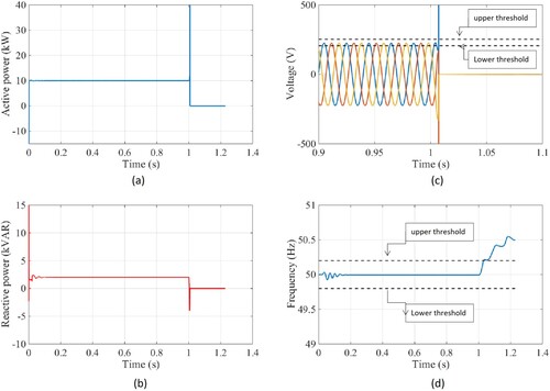
It can also be noticed that the voltage gets unstable after the fault occurrence where it oscillates beyond the upper threshold. At the same time, the frequency was also oscillating beyond the upper threshold as the DG is no more connected to the main grid. This means the phase synchronisation with the main grid is lost. Hence the over-frequency relay as well as the overvoltage relay into the fault detection scheme are triggered.
Furthermore, the active/reactive power, current and trip signal at PCC are presented in (a–d). It is clearly shown that the real and reactive power was 5 kW and 2 kVAR before the fault occurs and when the DG was working in grid-connected mode. However, they reach zero at t = 1s once the fault is detected. This is because the DG is now turned off and no more power is transferred to the main grid. Also, notice that the current reaches zero at the fault instant. This is an indication of the DG disconnection from the main grid. Also, notice that the fault detection scheme was at 0 state during the normal operating conditions. However, it changes to 1 state when the fault occurs, hence the current becomes zero as no more power comes from the DG.
Figure 9. Active/reactive power, current and trip signal at PCC during switch-off mode.
4.3. DG inverter under V/f control mode
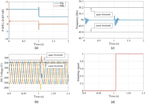
Unintentional islanding of the DG is assumed to occur at , where the DG should switch its control from grid-connected mode to autonomous mode once the fault detection scheme detects the fault existence. The active and reactive power transfer to the main grid should be zero as the DG is no more connected to the main grid. However, here the load demand will be satisfied by the DG itself instead of cutting off the supply as in the previous scenario when the DG is turned off.
(a–d) depicts the active/reactive power, voltage, frequency, and the trip signal at the DG bus before and after the fault occurrence. It can be seen that the DG was working successfully before t = 1s. However, once the fault detection scheme detects the fault, the DG switches its control to V/f control where the real power drops to 5 kW (exactly the same as the load demand) to continue supplying the load and the reactive power drops to zero as the load is only resistive. Note that how the voltage oscillates outside the permissible range at the fault instant (t = 1s). Once the measured voltage value exceeds the threshold limit, the DG is disconnected from the main grid and switches its operation to the V/f mode. Also, it can be seen how the voltage is stabilised after some few cycles. The frequency at the DG bus was also oscillating between the upper and lower thresholds. However, since the voltage monitoring inside the fault detection scheme was faster in detecting the fault, the frequency is recovered to normal operation as the v/f control mode is already running the DG. The trip signal issued from the fault detection scheme was at 0 state during the normal operating conditions. However, it changes to 1 state when the fault occurs, where one quantity either the voltage or the frequency needs to oscillate beyond the acceptable range so that it fault detection scheme is triggered.
Figure 10. Active/reactive power, voltage, frequency and trip signal at DG bus during V/f control mode.
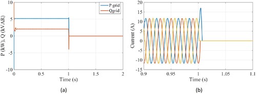
(a,b) depicts the rest of the real and reactive power and the current at the grid side after the DG supplies the required load demand. Before t = 1s, the DG was generating 10 kW where 5 kW was drawn from the load so the rest of active power 5 kW transfers to the main grid. After t = 1s, the generated 5 kW from the DG was drawn by the load and nothing transfers to the main grid as it is disconnected from the DG. The reactive power generated from the DG was 2kVAR and it appears the same at the grid side as the load is resistive. When the main grid is disconnected from the DG, the reactive power drops to zero. Besides, notice how the current reaches zero after the fault instant. This is an indication of the DG disconnection from the main grid.
Figure 11. Active/reactive power, current at PCC during V/f control mode.
5. Conclusions
Primary control is the main local control of the DG inverter which is applied by a variety of control methods. In this paper, the performance of the primary DG control unit including the fault detection scheme has been investigated under three case scenarios. During normal operating conditions, the DG control unit in grid-connected mode works properly in tracking the power references where the real and reactive power references have been regulated to 10 kW and 2 kVAR, respectively. The frequency and voltage are stable and within limits. During the switch-off mode, the power and reactive power at the DG bus and PCC reaches zero after as the inverter is switched off. This is because the voltage magnitude and frequency oscillate beyond the acceptable thresholds. Thus, the fault detection scheme operates and switches the control from grid-connected mode to turn-off mode. During V/f control mode, only the voltage oscillates beyond the acceptable thresholds after
. Therefore, the fault detection scheme is triggered and switches the control from grid-connected mode to V/f mode. Thus, the real power is dropped to 5 kW exactly the same as the needed load demand and the reactive power is dropped to zero as the load is only resistive. It has been found that grid-connected mode works properly in injecting the active and reactive power into the main grid. Also, it has been found that the fault detection scheme operates successfully when it detects the short circuit condition and switches the control of the DG either to the switch-off mode or to the V/f mode. Future work may include using an active method for fault detection rather than a passive method. Also, a seamless transfer scheme may be implemented to achieve smooth transfer between different modes of operation of the DG inverter.
Disclosure statement
No potential conflict of interest was reported by the authors.
References
- Ahmed, K., M. Seyedmahmoudian, S. Mekhilef, N.M. Mubarak, and A. Stojcevski. 2021. “A Review on Primary and Secondary Controls of Inverter-Interfaced Microgrid.” Journal of Modern Power Systems and Clean Energy 9 (5): 969–985. doi:10.35833/MPCE.2020.000068
- Alfergani, A., K.A. Alfaitori, A. Khalil, and N. Buaossa. 2018. “Control Strategies in AC Microgrid: A Brief Review.” In 9th International Renewable Energy Congress (IREC), Hammamet.
- Feng, X., A. Shekhar, F. Yang, R.E. Hebner, and P. Bauer. 2017. “Comparison of Hierarchical Control and Distributed Control for Microgrid.” Electric Power Components and Systems 45: 1043–1056. doi:10.1080/15325008.2017.1318982
- Fusero, M., A. Tuckey, A. Rosini, P. Serra, R. Procopio, and A. Bonfiglio. 2019. “A Comprehensive Inverter-BESS Primary Control for AC Microgrids.” Energies 12 (20): 3810. doi:10.3390/en12203810
- Guerrero, J.M., M. Chandorkar, T.-L. Lee, and P.C. Loh. 2013. “Advanced Control Architectures for Intelligent Microgrids—Part I: Decentralized and Hierarchical Control.” IEEE Transactions on Industrial Electronics 60 (4): 1254–1262. doi:10.1109/TIE.2012.2194969
- Guerrero, J.M., J.C. Vasquez, J. Matas, M. Castilla, and L.G.d. Vicuna. 2009. “Control Strategy for Flexible Microgrid Based on Parallel Line-Interactive UPS Systems.” IEEE Transactions on Industrial Electronics 56 (3): 726–736. doi:10.1109/TIE.2008.2009274
- Hamidi, R.J., H. Livani, S.H. Hosseinian, and G.B. Gharehpetian. 2016. “Distributed Cooperative Control System for Smart Microgrids.” Electric Power Systems Research 130: 241–250. doi:10.1016/j.epsr.2015.09.012
- Haque, M.E., M. Negnevitsky, and K.M. Muttaqi. 2010. “A Novel Control Strategy for a Variable-Speed Wind Turbine with a Permanent-Magnet Synchronous Generator.” IEEE Transactions on Industry Applications 46 (1): 331–339. doi:10.1109/TIA.2009.2036550
- Khanbaghi, M., and A. Zecevic. 2022. “Stochastic Distributed Control for Arbitrarily Connected Microgrid Clusters.” Energies 15 (14): 5163. doi:10.3390/en15145163
- Krishan, O., and S. Suhag. 2019. “An Updated Review of Energy Storage Systems: Classification and Applications in Distributed Generation Power Systems Incorporating Renewable Energy Resources.” International Journal of Energy Research 43: 6171–6210. doi:10.1002/er.4285
- Liu, J., H. Bevrani, and T. Ise. 2022. “A Design-Oriented Q-V Response Modeling Approach for Grid-Forming Distributed Generators Considering Different Operation Modes.” IEEE Journal of Emerging and Selected Topics in Power Electronics 10 (1): 387–401. doi:10.1109/JESTPE.2021.3057517
- Lu, D.R.a.T. 2022. “A Literature Review of the Control Challenges of Distributed Energy Resources Based on Microgrids (MGs): Past, Present and Future.” Energies 15: 1–20. doi:10.3390/en15134676
- Mehrasa, M., E. Pouresmaeil, B.N. Jørgensen, and J.P.S. Catalão. 2015. “A Control Plan for the Stable Operation of Microgrids During Grid-Connected and Islanded Modes.” Electric Power Systems Research 129: 10–22. doi:10.1016/j.epsr.2015.07.004
- Monopoli, V.G., and F. Ticali. 2020. “Passivity-Based Control of Grid-Forming Inverters in Presence of Constant-Power Loads.” International Review of Electrical Engineering (IREE) 15 (2): 99–107. doi:10.15866/iree.v15i2.18329
- Omar, M.A. 2020. “Control Scheme of Photovoltaic Inverter for Voltage Improvement in Isolated AC Microgrids.” International Review of Electrical Engineering (IREE) 15 (3): 199–205. doi:10.15866/iree.v15i3.18591
- Razmjoo, A., L. Kaigutha, M. Rad, M. Marzband, A. Davarpanah, and M. Denai. 2021. “A Technical Analysis Investigating Energy Sustainability Utilizing Reliable Renewable Energy Sources to Reduce CO2 Emissions in a High Potential Area.” Renewable Energy 164: 46–57. doi:10.1016/j.renene.2020.09.042
- Rokrok, E., M. Shafie-khah, and J.P.S. Catalão. 2018. “Review of Primary Voltage and Frequency Control Methods for Inverter-Based Islanded Microgrids with Distributed Generation.” Renewable and Sustainable Energy Reviews 82: 3225–3235. doi:10.1016/j.rser.2017.10.022
- Sahoo, S.K., A.K. Sinha, and N.K. Kishore. 2018. “Control Techniques in AC, DC, and Hybrid AC–DC Microgrid: A Review.” IEEE Journal of Emerging and Selected Topics in Power Electronics 6 (2): 738–759. doi:10.1109/JESTPE.2017.2786588
- Salem, Q., and K. Alzaareer. 2021. “Detailed Analysis of Grid Connected and Islanded Operation Modes Based on P/U and Q/f Droop Characteristics.” International Journal of Power Electronics and Drive System 12 (2): 772–782. doi:10.11591/ijpeds.v12.i2.pp772-782.
- Unamuno, E., and J.A. Barrena. 2016. “Equivalence of Primary Control Strategies for AC and DC Microgrids.” In 16th International Conference on Environment and Electrical Engineering (EEEIC), Florence.
- Vegunta, S., M. Higginson, Y. Kenarangui, G. Li, D. Zabel, M. Tasdighi, and A. Shadman. 2021. “AC Microgrid Protection System Design Challenges—A Practical Experience.” Energies 14 (7): 2016. doi:10.3390/en14072016
- Wu, D., F. Tang, T. Dragicevic, J.C. Vasquez, and J.M. Guerrero. 2014. “Autonomous Active Power Control for Islanded AC Microgrids With Photovoltaic Generation and Energy Storage System.” IEEE Transactions on Energy Conversion 29 (4): 882–892. doi:10.1109/TEC.2014.2358612
- Yamashita, D.Y., I. Vechiu, and J.-P. Gaubert. 2020. “A Review of Hierarchical Control for Building Microgrids.” Renewable and Sustainable Energy Reviews 118: 109523. doi:10.1016/j.rser.2019.109523
- Yazdani, S., M. Ferdowsi, and P. Shamsi. 2020. “Internal Model Based Smooth Transition of a Three-Phase Inverter Between Islanded and Grid-Connected Modes.” IEEE Transactions on Energy Conversion 35 (1): 405–415. doi:10.1109/TEC.2019.2936479
- Zhao, E., Y. Han, H. Zeng, L. Li, P. Yang, C. Wang, and A. Zalhaf. 2023. “Accurate Peer-to-Peer Hierarchical Control Method for Hybrid DC Microgrid Clusters.” Energies 16 (1). doi:10.3390/en16010421
