
 ?Mathematical formulae have been encoded as MathML and are displayed in this HTML version using MathJax in order to improve their display. Uncheck the box to turn MathJax off. This feature requires Javascript. Click on a formula to zoom.
Abstract
DC microgrids are now starting to attract huge attention from researches and engineers. Among the several DC microgrid architectures, bipolar DC microgrids are advantageous to accommodate a wider range of DC loads. However, due to mismatched loads connected to the two poles, bipolar DC microgrids may show voltage balancing issues. In this context, this article presents a new high input-to-output voltage gain, non-isolated DC–DC converter specifically designed for bipolar DC Microgrids. The proposed converter supports the balance of voltages at both bipolar DC microgrid poles, as the converter can transfer energy between the two poles in an unbalanced way. The description, theoretical support, and operation of the proposed converter will be presented. The theoretical assumptions will be complemented with several results obtained from computer simulation tests. The simulation tests will be compared to laboratory results from an experimental prototype. The obtained results confirm the theoretical properties of the proposed converter.
1. Introduction
Electrical infrastructures, especially at low voltage (LV), are facing a paradigm change. In fact, now instead of always using the classical AC grid, engineers have started to consider using DC grids (or microgrids) [Citation1–5]. DC grids present strong advantages over the classical AC grids, such as increased efficiency, no reactive power, and higher power transfer capability [Citation6–9]. In particular, the bipolar microgrid architecture provides two symmetrical DC voltages (+V, –V) and presents several advantages over most of the unipolar DC microgrid architectures [Citation10–13], namely the possibility to fed a broader range of power loads. Nevertheless, a bipolar microgrid may present a significant disadvantage related to the unbalance of the absolute values of the voltages in the positive (+V) and negative (–V) poles. This unbalance may be originated by asymmetries in the loads, generators, and storage systems connected to the two DC poles. For example, typical PV generators use a single input, single output DC–DC converter, therefore, feeding only one of the bipolar microgrid poles. Even if there are two PV generators, each one feeding its own DC microgrid pole, to avoid pole voltage unbalances, each PV generator must inject the exact energy needed for pole voltage balancing, considering the loads at each pole, therefore, impairing the PV generators maximum renewable power transfer capability. Hence, specifically designed DC–DC microgrid converters able to eliminate or mitigate microgrid pole unbalance issues are welcome.
Unbalance issues in bipolar DC microgrids can be mitigated through careful balancing over time, the power distribution among the two poles of devices, like generators, storage systems, and loads [Citation14, Citation15]. However, due to random variations in consumption and renewable generation, it is difficult, without using extra power converters, to ensure that the number of connected devices and their powers are such that the net power in both poles is exactly balanced over time. Therefore, the simple static equalizing balancing strategy will not ensure the balance of a bipolar DC microgrid as the number and power of loads and renewable generators change stochastically. A better strategy to balance the two voltages of bipolar DC microgrid poles uses an extra power electronic converter called a voltage balancer (VB) [Citation16–18]. A VB converter allows transferring the energy from one pole to the other pole, dynamically ensuring the balance of the two bipolar DC microgrid poles. However, besides the extra cost of the VB converter, it also introduces additional power losses. A third strategy to address the unbalance issue is to change the type of DC–DC converter used in generators like photovoltaic and/or fuel-cells. Instead of using the usual single-input single-output DC–DC converter, a multiport (single-input dual-output) DC–DC converter is devised. The multiport converter must be designed to transfer the energy as a function of the pole voltage unbalance [Citation19–25]. Thus, if the bipolar DC microgrid is balanced, supposing unbalanced loads, then, the energy must be transferred to the positive and negative poles in an unbalanced way. Otherwise, the multiport converter should transfer most of the energy to the pole with lower absolute voltage value.
Not many multiport converter topologies have been proposed for this type of bipolar DC microgrids, the subject still being a new area under study. As photovoltaic panels and fuel-cells present relatively low output voltage values, usually DC–DC converters processing the output power of these generators must have voltage boost characteristics [Citation26–30]. Consequently, the majority of the proposed topologies for bipolar DC microgrids are boost type converters. Additional features related to boost converters are galvanic isolation and high input-to-output voltage gain. Several high gain topologies based on high frequency transformers were proposed [Citation31–33]. However, transformer isolation presents some disadvantages like lower efficiency and core saturation issues. Thus, several proposals were made to use topologies without high frequency transformers. Some of these topologies are characterized by a typical boost feature, with the standard Boost DC–DC converter static input-to-output voltage gain or the double considering pole to pole voltage [Citation34–37]. However, although under the theoretical point of view the boost voltage gain can be very high, in practice due to the losses and voltage drops the standard boost presents a very limited voltage gain (<5). This limitation led to the proposal of several converters with extended static input-to-output voltage gains [Citation38–43]. Nevertheless, the high majority of the proposed converters with extended voltage gains are not well suited for bipolar DC microgrids since they have only a single output. Nevertheless, some extended gain converters were designed for two outputs and with the capability to operate in different conditions to support the balance of the microgrid. An interleaved Boost converter with Greinacher voltage multiplier cells was revealed in Ref. [Citation44]. A topology with an additional inductor added to a conventional three-level-boost converter was disclosed in Ref. [Citation45]. Another topology based on a boost converter integrated with a bipolar Dickson voltage multiplier was proposed in Ref. [Citation46]. A converter that allows for some extended voltage gain was also presented in work [Citation47]. An extended gain topology with continuous input current was also proposed in Ref. [Citation48]. However, some limitations of the aforementioned topologies include relatively high losses, discontinuous input current, high number of active semiconductor switches, or many passive components, especially inductors.
Regarding the importance of the development of DC–DC converters suited to address the unbalance issue of bipolar DC microgrids, this article proposes a new converter topology with capability to support the voltage balance of bipolar DC microgrids. The proposed self-balance dual output (SBDO) converter is characterized by high static input–output voltage gain, as well as, continuous input current (Section 2). The proposed self-balance dual output converter, developed aiming to reduce the number of passive components, is designed in Section 3. To show the claimed features and theoretical assumptions, the article includes several tests carried out by computer simulations (Section 4) and by a laboratory prototype (Section 5).
2. Proposed DC–DC SBDO Converter for Bipolar DC Microgrids
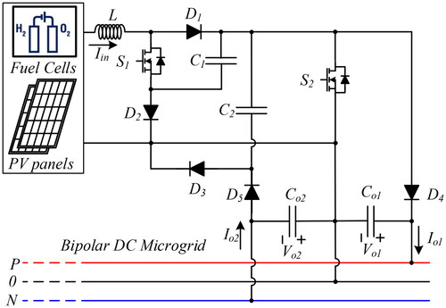
To mitigate voltage unbalances between the positive and negative poles of a DC bipolar microgrid, DC–DC power electronic converters, fed from PV panels or fuel cells, should have continuous input current and dual outputs to supply a bipolar DC microgrid. Taking into consideration these requirements, the new DC–DC power electronic SBDO converter topology is proposed, as shown in . The SBDO converter has a single inductive input for continuous input current and a double voltage source output to allow the transfer of the input power to the two poles of the bipolar DC microgrid in a balanced or unbalanced way. This feature contributes to the microgrid pole voltage balance. The proposed SBDO converter also features a boost characteristic with high input-to-output voltage gain.
FIGURE 1. Topology of the DC–DC SBDO converter designed to support the balancing of bipolar DC microgrids.
For continuous input current, the proposed topology must operate in the continuous conduction mode (CCM). In CCM, if the two switches (S1 and S2) operate synchronously, that is, when S1 is in the ON state S2 is also in the ON state and vice-versa, the SBDO converter has only two operation modes, as described hereafter:
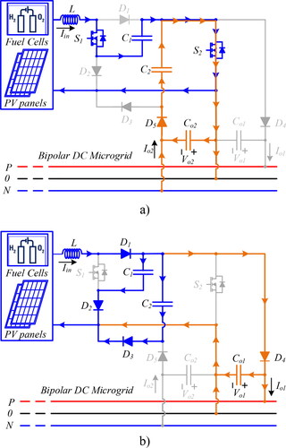
First operation mode - Mode 1 - (switches S1 and S2 ON, t0–t1): During the time span where both switches are ON (), inductor L will receive energy from the DC source (e.g., PV panel), aided by the discharge of capacitor C1 in series with said DC source via S1 and S2. If the absolute value of the negative pole voltage Vo2 is smaller or equals the capacitor C2 voltage VC2, then, some energy from capacitor C2 will be transferred to the negative pole capacitor Co2, via S2 D5, up to the equilibrium of these two capacitor voltages. Therefore, the negative pole voltage Vo2 is linked to the capacitor C2 voltage VC2, except if |Vo2|> VC2. In this case, there is no energy transfer from capacitor C2, up to the moment where the discharge of Co2 will lead to VC2>|Vo2|.
Second operation mode - Mode 2 - (both switches OFF, t1–T): During this time span both switches are OFF (). In Mode 2, the energy stored in inductor L can be transferred, via D1, to capacitor C1, to capacitor C2 and to the output positive pole capacitor Co1, via diodes D2, D3, and D4, respectively. These three capacitors are connected in parallel through the diodes. Therefore, the positive pole voltage Vo1 is linked to the capacitor C2 voltage VC2, except if Vo1 > VC2. In this case, there is no energy transfer from capacitor C2 to capacitor Co1, until Vo1 < VC2.
FIGURE 2. First (a) and second (b) operation modes of the SBDO converter designed to be used in bipolar DC microgrids.
The proposed SBDO converter addresses the voltage balancing issues of bipolar DC microgrids in the following ways:
In Mode 1, if |Vo2| > VC2 no power is transferred from C2 to Co2, until Co2 is sufficiently discharged, therefore, promoting |Vo2| ≈ VC2;
In Mode 2, if Vo1> VC2 no power is transferred to Co1, until Co1 is sufficiently discharged, therefore, promoting Vo1 ≈ VC2;
if |Vo2|> VC2 power is only transferred to the positive pole (during Mode 2);
if Vo1> VC2 power is only transferred to the negative pole (during Mode 1);
if |Vo2| ≈ Vo1 ≈ VC2 power is transferred to the positive pole during Mode 2 and to the negative pole during Mode 1.
The combined effect of the two modes gives |Vo2| ≈ Vo1 ≈ VC2, therefore, self-eliminating voltage unbalances in the bipolar microgrid.
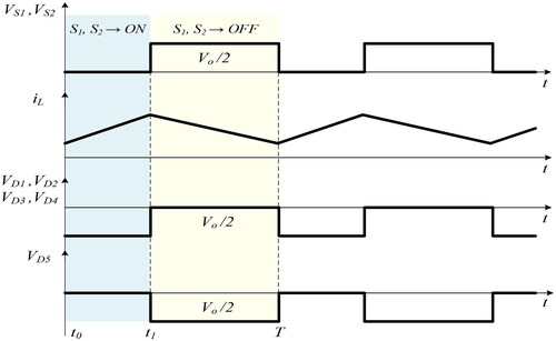
Regarding the typical waveforms () associated to the proposed SBDO converter, it can be seen that the current in inductor L, iL, rises during Mode 1 and decreases during Mode 2, being iL(t) > 0 to guarantee operation in CCM. The current variation can be made small enough for the PV or fuel-cell generator optimum operation by designing the inductance value for a given switching frequency. The microgrid output voltages |Vo2|, Vo1, and capacitor voltage VC2 are nearly constant and show nearly equal average values. The voltages at the terminals of the active semiconductors VS1, VS2, and diodes VD1, VD2, VD3, VD4, and VD5, show semiconductors have to sustain only half of the total output voltage.
FIGURE 3. Current and voltage waveforms associated to the CCM of the proposed SBDO converter to be used in bipolar DC microgrids.
To determine the static input-to-output voltage gain, steady-state is considered at nearly constant capacitor voltages to apply the inductor volt-second balance principle. The inductor average voltage is zero in steady-state. Considering the duty cycle δ of both switches, (being δ = (t1/T)), the average value of the inductor voltage is:
(1)
(1)
From Mode 2, it is concluded that VC2 ≈ VC1 and Vo1 ≈ VC2. From Mode 1, it is concluded that |Vo2| ≈ VC2. Therefore, Vo1 ≈ |Vo2| ≈ VC1:
(2)
(2)
The total static input-to-output voltage gain of the proposed SBDO converter, it is given by:
(3)
(3)
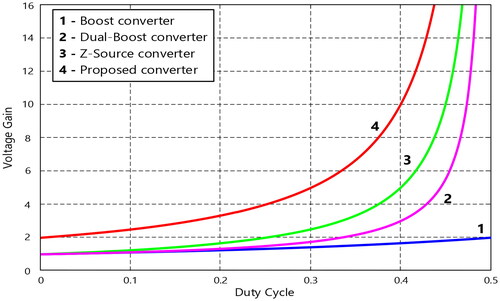
From the static input-to-output voltage gain of the SBDO converter given in Equation(3)(3)
(3) , it is seen that the SBDO converter allows a relatively high gain. presents a comparison of the static input-to-output voltage gain of the SBDO converter regarding the classical Boost, the dual Boost, and the Z-source converter.
FIGURE 4. Comparison of the static input-to-output voltage gain function of the duty cycle between the classical Boost, the dual Boost, the Z-source converter, and the proposed SBDO converter.
3. Design of the SBDO Converter
The design of the SBDO converter assumes the CCM operation, ideal semiconductor devices and circuit components together with the relationships presented in the previous section.
As the SBDO converter is assumed to be conservative, the input power equals the output power. Therefore, the inductor current average value is expressed by Equation(9)(9)
(9) .
(4)
(4)
The design of the inductor and capacitors will take into consideration the rated voltages and current in these components, as well as, the limitation of the ripples of the current in the inductor and of the voltage in the capacitors. Considering expressions Equation(1)(1)
(1) and Equation(5)
(5)
(5) , the condition to size the inductance is:
(5)
(5)
To size the capacitances, the rate of change of the capacitor voltage Equation(6)(6)
(6) is assumed to be proportional to the capacitor current. Then, the equations to size the capacitances Co1 = Co2, C1, C2 = C3, are given by Equation(7)
(7)
(7) , Equation(8)
(8)
(8) , and Equation(9)
(9)
(9) , respectively.
(6)
(6)
(7)
(7)
(8)
(8)
(9)
(9)
The previous assumptions will also be used to determine the power semiconductor ratings. The power semiconductors (transistors and diodes) current ratings will be given by expressions Equation(10)(10)
(10) to Equation(13)
(13)
(13) .
(10)
(10)
(11)
(11)
(12)
(12)
(13)
(13)
The power semiconductors voltage ratings are estimated neglecting the voltage ripple in the capacitors. The minimum voltage capability required for each power semiconductor is given by expressions Equation(14)(14)
(14) and Equation(15)
(15)
(15) .
(14)
(14)
(15)
(15)
4. Simulation Results
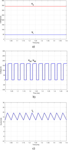
This section presents some simulation results of the proposed DC–DC SBDO converter using the MATLAB/Simulink software. The proposed SBDO converter component values for capacitors are Co1 = Co2 = 470 µF, C1 = C2 = 48 µF and for inductor L = 600 µH. The SBDO converter is supplied by a single DC voltage source of 48 VDC and the output of the bipolar DC microgrid was adjusted through the duty cycle to obtain ±170 VDC, which is a quite common voltage for bipolar DC microgrids. The switching frequency selected was 20 kHz and the initial load was considered to equal 140 Ω in each pole. The operation mode of the DC–DC SBDO converter was tested in CCM and steady-state. The first simulation result presents the input and output voltages of the SBDO converter () showing the obtained voltage gain from 48 VDC to 340 VDC (total voltage). shows the voltage over the power devices with a switching frequency of 20 kHz and a duty-cycle of 0.36. This figure shows that the maximum hold-off voltage in each power device is around 170 V. The input current (see ) in the inductor L of the SBDO converter shows the CCM operation at an average value around 15 A. The nearly 7 A peak-to-peak ripple allows expecting CCM operation of the SBDO converter down to nearly 3.5 A input inductor averaged current.
FIGURE 5. Results obtained by simulation of the SBDO converter designed for the bipolar DC microgrid: (a) voltages of the input source and SBDO converter output; (b) voltages over transistors S1 and S2; (c) input current of the proposed SBDO converter.
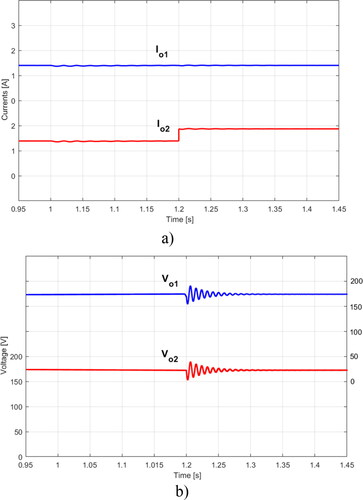
The capability of the proposed SBDO converter to support the bipolar DC microgrid voltages with unbalanced loads was evaluated creating a simulated transient test. Prior to the transient test, the microgrid was balanced (considering the same load in each pole). After t = 1.2 msec the load of the negative pole changed from 140 Ω to 100 Ω, resulting in a current increment as can be seen in . This figure shows that only the output current (Io2) associated to the negative pole increases while the current of the positive pole (Io1) remains constant. confirms that the positive output voltage average value is not affected by the unbalance in the negative pole load, as the average values of |Vo2| ≈ Vo1 do not change significantly, in spite of the shown transient in the instantaneous pole voltages to accommodate the load unbalance. This confirms that the operation of the SBDO converter allows more energy transfer for the pole that most requires it.
FIGURE 6. Results obtained by simulation of the SBDO converter designed for the bipolar DC microgrid when there is a suddenly change in the load connected to the negative pole: (a) Output currents of the proposed SBDO converter and (b) voltages across capacitors C1 and C2.
5. Experimental Results
This section presents some experimental tests and obtained results using a laboratory prototype. These experiments tests were made using components with similar values to those presented in the simulation section. All the tests were executed with a duty-cycle providing CCM operation.
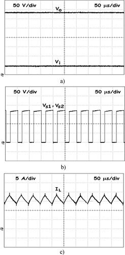
Similarly to the simulation tests, the first experimental test was performed in steady state conditions and balanced loads in the bipolar DC microgrid. The obtained voltage gain can be seen in . Considering an input voltage of 48 VDC, it was obtained a total output voltage over 340 VDC which demonstrates the high input-to-output voltage gain of the proposed SBDO converter. Similarly, the voltage over the power devices and input current can be seen in and Citation7(c). Observing these results it is possible to conclude that they are similar to those shown in the simulation and with agreement with the theoretical analysis.
FIGURE 7. Results obtained through laboratory tests of the SBDO converter designed for the bipolar DC microgrid: (a) voltages of the input source and SBDO converter output; (b) voltages over transistors S1 and S2; (c) input current of the proposed SBDO converter.
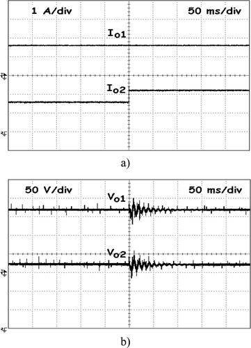
An experimental transient analysis was also made to demonstrate the proposed SBDO converter capability to support unbalanced loads in the bipolar DC microgrid. In the beginning of this second experimental test, the loads connected to the two microgrid DC poles were nearly equal to obtain balanced operation. Then, after some time, in the microgrid negative pole an additional resistive load was manually switched on to create an unbalanced condition. shows the abrupt increase in the negative DC pole current at the instant in which the load was switched on. As the added load is resistive almost no current establishing transient can be seen. After the fast transient mode the input current stabilizes around a higher average value. Conversely, the current in the positive remains constant, which indicates that the positive output voltage is not affected by the unbalance in the negative pole load. This demonstrates that a load change in one DC pole, does not affect the other pole, implying only current variations in the pole current itself and in the SBDO converter input current. also shows the transient behavior of the SBDO converter voltages to load variation, which present dynamics with acceptable transient response.
FIGURE 8. Results obtained through laboratory tests of the SBDO converter designed for the bipolar DC microgrid when there is a suddenly change in the load connected to the negative pole: (a) Output currents of the proposed SBDO converter and (b) voltages across capacitors C1 and C2.
6. Conclusions
This work addressed the problem of bipolar microgrids voltage unbalance, through the proposal of a new self-balance dual output converter to be powered from photovoltaic panels or fuel cells. The proposed SBDO converter presents boost characteristics with high input-to-output voltage gain, continuous input current, and dual complementary output. Since in bipolar DC microgrids voltage unbalances between their poles may appear, mainly due to load unbalance, the proposed SBDO converter allows to transfer of energy to the dual output in a balanced or unbalanced way. If the voltage absolute value at one of the poles is lower than the voltage at the other pole, then the SBDO converter will only transfer energy to the pole with the lower voltage helping to achieve the microgrid balance. Another characteristic of the SBDO converter is that it uses only two active switches that operate synchronously. Besides the description of the operation of the proposed SBDO converter, the article also presented the design of the topology. To confirm the referred characteristics of the proposed SBDO converter, several tests were performed. These tests were made in two different ways, namely through computer simulations and using a laboratory prototype. The results obtained in simulations and in the laboratory confirmed the important SBDO converter feature to correctly operate in balanced or unbalanced load conditions. In fact, when the DC microgrid was balanced, the SBDO converter delivered the energy in a balanced way to the positive and negative poles. However, when the microgrid was unbalanced, the results showed that the energy was only transferred to the pole with the voltage with a lower absolute value. The shown results confirm the suitability of the SBDO converter to be used in bipolar DC microgrids.
Additional information
Funding
Notes on contributors
Vitor Fernão Pires
Vitor Fernão Pires received the B.S. degree in Electrical Engineering from Institute Superior of Engineering of Lisbon, Portugal, in 1988 and the M.S. and Ph.D. Degrees in Electrical and Computer Engineering from Technical University of Lisbon, Portugal, in 1995 and 2000, respectively. Since 1991 he is a member of the teaching staff at Electrical Engineering Department of Superior Technical School of Setúbal – Polytechnic Institute of Setúbal. Presently he is a Professor, teaching Power Electronics and Control of Power Converters. He is also researcher at Instituto de Engenharia de Sistemas e Computadores, Investigação e Desenvolvimento em Lisboa (INESC-ID). His work has resulted in more than 300 publications. His present research interests include the areas of power-electronic converters, fault diagnosis and fault tolerant operation, renewable energy, electrical vehicles, electrical drives, and power quality.
Armando Cordeiro
Armando Cordeiro was born in Portugal in 1976, received his B.S. degree in Electrical Engineering from Instituto Superior de Engenharia de Lisboa in 1999. He received the M.Sc. and Ph.D. degrees in Electrical Engineering from IST, Technical University of Lisbon, in 2004 and 2015, respectively. His research interests include power electronics, variable speed drives, automation systems and electrical vehicles. He is also professor at the Department of Electrical Engineering and Automation of Instituto Superior de Engenharia de Lisboa for the area of Automation since 2006. His present research interests include the areas of power-electronic converters, industrial automation and robotics.
Daniel Foito
Daniel Foito received the Dipl. Ing. and M.S. degrees in electrical engineering from Instituto Superior Técnico, Technical University of Lisbon, Lisbon, Portugal in 1993 and 2002, respectively. He received Ph.D. degrees in electrical engineering from Faculty of Sciences and Technology, Universidade Nova de Lisboa, Portugal in 2015. Since 1997 he is a member of the teaching staff at Electrical Engineering Department of Superior Technical School of Setúbal – Polytechnic Institute of Setúbal. Presently he is a Adjoint Professor, teaching Power Electronics and Electric Drives. His research interests include renewable energy generation, electrical machines, electric drives, electric vehicle, fault diagnosis and fault tolerant operation.
José Fernando Silva
José Fernando Silva was born in Monção Portugal in 1956. He received the Dipl. Ing. in electrical engineering (1980) and the Doctor degree in electrical and computer engineering (power electronics and control) in 1990, from Instituto Superior Técnico (IST), Universidade Técnica de Lisboa (UTL), Lisbon, Portugal. He is a full professor of Power Electronics and Energy Storage in the scientific area of Energy, Department of Electrical and Computer Engineering of Instituto Superior Técnico (IST), Universidade de Lisboa (UL). He is senior researcher at Instituto de Engenharia de Sistemas e Computadores - Investigação e Desenvolvimento em Lisboa (INESC-ID) and currently the leader of the Research Line Energy Systems and the leader of the research group Power Electronics and Power Quality. He is IEEE Senior Member since 2001, Associate Editor of IEEE Transactions on Industrial Electronics from 2000 to 2019, member of the Industrial Electronics Magazine editorial board since 2010, and a member of the Portuguese Engineering Society. His research interests include electric power components and systems.
References
- F. S. Al-Ismail, “DC microgrid planning, operation, and control: A comprehensive review,” IEEE Access, vol. 9, pp. 36154–36172, Mar. 2021.
- J. J. Martínez-Nolasco et al., “Design and implementation of an embedded control system for the interconnection of a DC microgrid to the AC main network,” Electr. Power Compon. Syst., vol. 48, no. 6–7, pp. 527–542, Aug. 2020. DOI: 10.1080/15325008.2020.1797932.
- Z. Ali et al., “Fault management in DC microgrids: A review of challenges, countermeasures, and future research trends,” IEEE Access, vol. 9, pp. 128032–128054, Sept. 2021. DOI: 10.1109/ACCESS.2021.3112383.
- S. Sagiroglu, Y. Canbay, and I. Colak, “Solutions and suggestions for smart grid threats and vulnerabilities,” Int. J. Renew. Energy Res., vol. 9, no. 4, pp. 2053–2063, Dec. 2019.
- A. Shahid, “Smart grid integration of renewable energy systems,” presented at the 7th Int. Conf. Renew. Energy Res. Appl., Paris, France, Oct. 2018, pp. 944–948.
- K. Bharath, M. Krishnan, and P. Kanakasabapathy, “A review on DC microgrid control techniques, applications and trends,” Int. J. Renew. Energy Res., vol. 9, no. 3, pp. 1328–1338, Sept. 2019.
- F. Zhang et al., “Advantages and challenges of DC microgrid for commercial building a case study from Xiamen university DC microgrid,” presented at the IEEE First Int. Conf. DC Microgrids, Jun. 2015, pp. 355–358.
- M. Y. Nguyen and Y. T. Yoon, “A comparison of microgrid topologies considering both market operations and reliability,” Electr. Power Compon. Syst., vol. 42, no. 6, pp. 585–594, Mar. 2014. DOI: 10.1080/15325008.2014.880963.
- E. Irmak, N. Güler, E. Kabalcı, and A. Calpbinici, “A modified droop control method for PV systems in island mode DC microgrid,” presented at the 8th Int. Conf. Renew. Energy Res. Appl., Brasov, Romania, Nov. 2019, pp. 1008–1013.
- H. Kakigano, Y. Miura, and T. Ise, “Low-voltage bipolar-type DC microgrid for super high quality distribution,” IEEE Trans. Power Electron., vol. 25, no. 12, pp. 3066–3075, Dec. 2010. DOI: 10.1109/TPEL.2010.2077682.
- T. Dragičević, X. Lu, J. C. Vasquez, and J. M. Guerrero, “DC microgrids—Part II: A review of power architectures, applications, and standardization issues,” IEEE Trans. Power Electron., vol. 31, no. 5, pp. 3528–3549, May 2016. DOI: 10.1109/TPEL.2015.2464277.
- L. Mackay, N. H. van der Blij, L. Ramirez-Elizondo, and P. Bauer, “Toward the universal DC distribution system,” Electr. Power Compon. Syst., vol. 45, no. 10, pp. 1032–1042, Jul. 2017. DOI: 10.1080/15325008.2017.1318977.
- S. Rivera, R. Lizana F, S. Kouro, T. Dragičević, and B. Wu, “Bipolar DC power conversion: State-of-the-art and emerging technologies,” IEEE J. Emerg. Sel. Top. Power Electron., vol. 9, no. 2, pp. 1192–1204, Apr. 2021. DOI: 10.1109/JESTPE.2020.2980994.
- G. Gwon et al., “Mitigation of voltage unbalance by using static load transfer switch in bipolar low voltage DC distribution system,” Int. J. Electr. Power Energy Syst., vol. 90, pp. 158–167, Sept. 2017. DOI: 10.1016/j.ijepes.2017.02.009.
- R. Babazadeh-Dizaji, M. Hamzeh, and N. M. Dehkordi, “A resilient bi-level control strategy for power sharing and voltage balancing in bipolar DC microgrids,” IET Gener. Transm. Distrib., vol. 16, no. 17, pp. 3402–3415, Sept. 2022. DOI: 10.1049/gtd2.12530.
- V. Fernão Pires, A. Cordeiro, C. Roncero-Clemente, S. Rivera, and T. Dragičević, “DC-DC converters for bipolar microgrid voltage balancing: A comprehensive review of architectures and topologies,” IEEE J. Emerg. Select. Top. Power Electron., 2022. DOI: 10.1109/JESTPE.2022.3208689.
- Q. Xu et al., “Review on advanced control technologies for bidirectional DC/DC converters in DC microgrids,” IEEE J. Emerg. Sel. Top. Power Electron., vol. 9, no. 2, pp. 1205–1221, Apr. 2021. DOI: 10.1109/JESTPE.2020.2978064.
- J.-O. Lee, Y.-S. Kim, and S.-I. Moon, “Current injection power flow analysis and optimal generation dispatch for bipolar dc microgrids,” IEEE Trans. Smart Grid, vol. 12, no. 3, pp. 1918–1928, May 2021. DOI: 10.1109/TSG.2020.3046733.
- S. Rezayi, H. Iman-Eini, M. Hamzeh, S. Bacha, and S. Farzamkia, “Dual-output DC/DC boost converter for bipolar DC microgrids,” IET Renew. Power Gener., vol. 13, no. 8, pp. 1402–1410, Jun. 2019. DOI: 10.1049/iet-rpg.2018.6167.
- M. B. Ferrera, S. P. Litrán, E. Durán Aranda, and J. M. Andújar Márquez, “A converter for bipolar DC link based on SEPIC-Cuk combination,” IEEE Trans. Power Electron., vol. 30, no. 12, pp. 6483–6487, Dec. 2015. DOI: 10.1109/TPEL.2015.2429745.
- V. F. Pires, D. Foito, and J. F. Silva, “A single switch hybrid DC/DC converter with extended static gain for photovoltaic applications,” Electr. Power Syst. Res., vol. 146, pp. 228–235, May 2017. DOI: 10.1016/j.epsr.2017.02.001.
- S. Markkassery, A. Saradagi, A. D. Mahindrakar, N. Lakshminarasamma, and R. Pasumarthy, “Modeling, design and control of non-isolated single-input multi-output zeta-buck-boost converter,” IEEE Trans. Ind. Appl., vol. 56, no. 4, pp. 3904–3918, Aug. 2020.
- E. D. Aranda, S. P. Litrán, and M. B. F. Prieto, “Combination of interleaved single-input multiple-output DC-DC converters,” CSEE J. Power Energy Syst., vol. 8, no. 1, pp. 132–142, Jan. 2022.
- V. F. Pires et al., “Interlink converter for hybrid AC to bipolar DC microgrid or to two DC microgrids,” presented at the 48th Annu. Conf. Ind. Electron. Soc., Brussels, Belgium, Oct. 17–20, 2022, pp. 1–6.
- J. Rajesh, K. S. Nisha, A. K. Bonala, and S. R. Sandepudi, “Predictive control of three level boost converter interfaced SPV system for bi-polar DC micro grid,” presented at the IEEE Int. Conf. Electr. Comput. Commun. Technol., Coimbatore, India, Feb. 2019, pp. 1–6.
- C. Lupangu, A. K. Saha, R. C. Bansal, and J. J. Justo, “Critical performance comparison between single-stage and two-stage incremental conductance MPPT algorithms for DC/DC boost-converter applied in PV systems,” Electr. Power Compon. Syst., vol. 50, no. 4–5, pp. 207–222, 2022. DOI: 10.1080/15325008.2022.2136286.
- E. Ribeiro, A. J. M. Cardoso, and C. Boccaletti, “Fault-tolerant strategy for a photovoltaic DC–DC converter,” IEEE Trans. Power Electron., vol. 28, no. 6, pp. 3008–3018, Jun. 2013. DOI: 10.1109/TPEL.2012.2226059.
- S. Mane, P. Kadam, G. Lahoti, F. Kazi, and N. M. Singh, “Optimal load balancing strategy for hybrid energy management system in DC microgrid with PV, fuel cell and battery storage,” presented at the IEEE Int. Conf. Renew. Energy Res. Appl., Birmingham, UK, Nov. 2016, pp. 851–856.
- M. Zdiri, M. Ammar, B. Bouzidi, R. Abdelhamid, and H. Abdallah, “An advanced switch failure diagnosis method and fault tolerant strategy in photovoltaic boost converter,” Electr. Power Compon. Syst., vol. 48, no. 18, pp. 1932–1944, 2020. DOI: 10.1080/15325008.2021.1909182.
- A. Abusorrah et al., “Stability of a boost converter fed from photovoltaic source,” Sol. Energy, vol. 98, Part C, pp. 458–471, Dec. 2013.
- N. D. Dao, D. Lee, and Q. D. Phan, “High-efficiency SiC-based isolated three-port DC/DC converters for hybrid charging stations,” IEEE Trans. Power Electron., vol. 35, no. 10, pp. 10455–10465, Oct. 2020. DOI: 10.1109/TPEL.2020.2975124.
- H.-J. Byun, S.-H. Kim, S.-H. Kim, J. Yi, and C.-Y. Won, “Input-series-output-parallel DAB converter on energy storage system for voltage balancing strategy in bipolar DC microgrid,” presented at the 24th Int. Conf. Electr. Mach. Syst., Gyeongju, Korea, Republic of, Nov. 2021, pp. 818–823.
- H. Jou, J. Huang, J. Wu, and K. Wu, “Novel isolated multilevel DC-DC power converter,” IEEE Trans. Power Electron., vol. 31, no. 4, pp. 2690–2694, Apr. 2016. DOI: 10.1109/TPEL.2015.2487558.
- Y. Zhang, L. Zhou, M. Sumner, and P. Wang, “Single-switch, wide voltage gain range, boost DC-DC converter for fuel cell vehicles,” IEEE Trans. Veh. Technol., vol. 67, no. 1, pp. 134–145, Jan. 2018. DOI: 10.1109/TVT.2017.2772087.
- J. L. Durán-Gómez, E. García-Cervantes, D. R. López-Flores, P. N. Enjeti, and L. Palma, “Analysis and evaluation of a series-combined connected boost and buck-boost dc-dc converter for photovoltaic application”, presented at the IEEE Appl. Power Electron. Conf. Exp., Dallas, TX, USA, Mar. 2006, pp. 19–23.
- K. Haddad, “Three level DC–DC converters as efficient interface in two stage PV power systems,” presented at the IEEE Energytech, Cleveland, OH, USA, May 2012, pp. 1–6.
- X. Ruan, B. Li, Q. Chen, S. Tan, and C. K. Tse, “Fundamental considerations of three-level DC-DC converters: Topologies, analyses, and control,” IEEE Trans. Circuits Syst. I, vol. 55, no. 11, pp. 3733–3743, Dec. 2008. DOI: 10.1109/TCSI.2008.927218.
- V. F. Pires, A. Cordeiro, D. Foito, and J. F. Silva, “A DC-DC converter with capability to support the voltage balance of DC bipolar microgrids,” presented at the 11th Int. Conf. Renew. Energy Res. Appl. (ICRERA), Istanbul, Turkey, Sept. 2022, pp. 50–55.
- S. Padmanaban, F. Blaabjerg, P. Wheeler, J. O. Ojo, and A. H. Ertas, “High-voltage DC-DC converter topology for PV energy utilization—investigation and implementation,” Electr. Power Compon. Syst., vol. 45, no. 3, pp. 221–232, 2017. DOI: 10.1080/15325008.2016.1248251.
- M. Yasir, A. Khan, H. Liu, S. M. Hashemzadeh, and X. Yuan, “A novel high step-up DC–DC converter with improved P&O MPPT for photovoltaic applications,” Electr. Power Compon. Syst., vol. 49, no. 9–10, pp. 884–900, Apr. 2022.
- Z. Saadatizadeh, P. C. Heris, M. Sabahi, and E. Babaei, “A DC–DC transformerless high voltage gain converter with low voltage stresses on switches and diodes,” IEEE Trans. Power Electron., vol. 34, no. 11, pp. 10600–10609, Nov. 2019. DOI: 10.1109/TPEL.2019.2900212.
- Y. T. R. Palleswari and V. Rajendran, “A novel hybrid high gain DC-DC converter for renewable energy applications,” Int. J. Renew. Energy Res., vol. 12, no. 1, pp. 88–96, Mar. 2022.
- W. Hassan, D. D.-C. Lu, and W. Xiao, “Single-switch high step-up DC–DC converter with low and steady switch voltage stress,” IEEE Trans. Ind. Electron., vol. 66, no. 12, pp. 9326–9338, Dec. 2019. DOI: 10.1109/TIE.2019.2893833.
- A. Alzahrani, P. Shamsi, and M. Ferdowsi, “A novel interleaved non-isolated high-gain DC-DC boost converter with Greinacher voltage multiplier cells,” presented at the IEEE 6th Int. Conf. Renew. Energy Res. Appl., San Diego, CA, USA, November 2017, pp. 222–227.
- H. Kang and H. Cha, “A new nonisolated high-voltage-gain boost converter with inherent output voltage balancing,” IEEE Trans. Ind. Electron., vol. 65, no. 3, pp. 2189–2198, Mar. 2018. DOI: 10.1109/TIE.2017.2736508.
- A. Alzahrani, P. Shamsi, and M. Ferdowsi, “Boost converter with bipolar Dickson voltage multiplier cells,” presented at the 6th Int. Conf. Renew. Energy Res. Appl., San Diego, CA, USA, November 2017, pp. 228–233.
- I. Ninma Jiya, H. Van Khang, N. Kishor, and R. M. Ciric, “Novel family of high-gain nonisolated multiport converters with bipolar symmetric outputs for DC microgrids,” IEEE Trans. Power Electron., vol. 37, no. 10, pp. 12151–12166, Oct. 2022. DOI: 10.1109/TPEL.2022.3176688.
- V. F. Pires, A. Cordeiro, D. Foito, and J. F. A. Silva, “Dual output and high voltage gain DC-DC converter for PV and fuel cell generators connected to DC bipolar microgrids,” IEEE Access, vol. 9, pp. 157124–157133, Oct. 2021. DOI: 10.1109/ACCESS.2021.3122877.