Abstract
Objective: Safety impact methodologies (SIMs) have the goal of estimating safety benefits for proposed active safety systems. Because the precrash movements of vehicles involved in real-world crashes are often unknown, previous SIMs have taken the approach to reconstruct collisions from incomplete information sources, such as scaled scene diagrams and photographic evidence. The objective of this study is to introduce a novel methodology for reconstructing the precrash vehicle trajectories using data from advanced event data recorders (EDRs).
Methods: Some EDRs from model year 2009 and newer Ford vehicles can record steering wheel angle in addition to precrash vehicle speed, accelerator pedal, and throttle input prior to the crash. A model was constructed using these precrash records and a vehicle model developed in the simulation software PreScan. The model was validated using the yaw rate and longitudinal and lateral accelerations also recorded by this type of Ford EDR but not used to develop the models.
Results: In general, the model was able to approximate the dynamics recorded on the EDR. The model did not match the observed dynamics when either the vehicle departed the paved surface or when electronic stability control was active. Modifying the surface friction at the estimated point at which the vehicle departed the road produced better simulation results. The developed trajectories were used to simulate 2 road departure crashes, one into a fixed object and one into a vehicle traveling in the opposite direction, as if the departing vehicle were equipped with a lane departure warning (LDW) system. This example application demonstrates the utility of this method and its potential application to a SIM.
Conclusions: This study demonstrated a novel method for crash reconstruction that can be applied to a SIM for active safety systems. Benefits of this method are that the driver inputs do not need to be inferred from other reconstructions because they are recorded directly by the EDR. Currently, there are too few cases with the advanced EDR data to estimate fleet-wide benefits of a system. Because of recent regulation (49 CFR Part 563), EDRs are likely to be downloaded in more real-world crashes, making this method a potentially valuable and low-cost method for developing SIMs in the future.
Supplemental materials are available for this article. Go to the publisher's online edition of Traffic Injury Prevention to view the supplemental file.
Introduction
Active safety systems hold great promise as a means of avoiding or mitigating traffic crashes and the ensuing injury outcomes. In contrast to passive safety devices such as seat belts that mitigate the consequences of a crash after it occurs, active safety systems, also known as collision avoidance systems, interact with the driver to prevent or mitigate a collision. These systems, however, frequently require expensive sensors, computation, and HMI (human machine interface) technologies. As a result, these expensive systems are typically offered as add-on options mostly on luxury brands. Automakers and government seek to estimate the potential safety benefits of these systems prior to their introduction into the fleet. Automakers need to justify developing these systems on high-volume, non-luxury vehicles. Regulators are weighing the choice of whether and how to regulate these emerging systems.
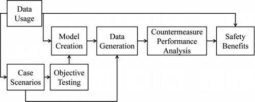
One widely accepted method for estimation of active safety benefits are safety impact methodologies (SIM). A SIM is a framework for estimating “potential safety benefits of pre- production advanced Driver Assistance Systems (DAS)” (Carter et al. Citation2009; Funke et al. Citation2011). This framework was introduced by the National Highway Traffic Safety Administration (NHTSA) and was the basis for a series of research projects under the Advanced Crash Avoidance Technology (ACAT) program. The schematic for the SIM framework is shown in . Data from national crash databases are the basis for identifying relevant crash scenarios for the technology being evaluated. Objective testing obtained by hardware and test track tests is used to create a computer model of the relevant crash scenarios and proposed system. Using the computer model, data are generated to form a population of virtual crashes. Countermeasure performance is then determined by comparing the virtual crash population before and after implementation of the safety system and these results are used to compute safety benefits of the system.
Fig. 1 SIM framework developed by the NHTSA (Carter et al. Citation2009; Funke et al. Citation2011).
The majority of the effort in the already completed ACAT projects was in creating a computer model of the relevant crash types. Several approaches were taken to create these virtual crash populations. The Volvo–Ford-UMTRI (University of Michigan Transportation Research Institute) ACAT project investigated lane departure warning benefits and created a Monte Carlo–type model. The Monte Carlo approach simulated an entire crash population by drawing model parameters from distributions created from various real-world data sets (Gordon et al. Citation2010). Another approach was used by the Honda–DRI ACAT project on precrash braking systems. Instead of simulating a large number of cases to approximate the crash population, they reconstructed individual crashes and simulated them as if a braking system was equipped in the striking vehicle (Van Auken et al. Citation2011).
The ACAT projects used simulation to estimate potential benefits because the adoption of these systems in the vehicle fleet is not sufficient to perform a retrospective analysis of benefits. One early retrospective study by Isaksson-Hellman and Lindman (Citation2012) was able to determine that a Volvo FCAS system reduced insurance claims by 23 percent for a single vehicle model using Swedish data. Due to the low market penetration cited earlier, these retrospective studies are still years away from being feasible in the United States.
A review of intelligent transport system effectiveness by Bayly et al. (Citation2007) summarized the results of studies of expected fleet-wide benefits for some proposed systems, including FCW (Forward Collision Warning) and lane departure warning (LDW). Studies pertaining specifically to rear-end collisions reported a range of crashes prevented from as low as 7 percent to as high as 80 percent. Benefits in these studies were often implied from an assumed proportion of a target population that would benefit from FCW without considering the effectiveness of the systems on a case-by-case basis. Although every collision is different, these traditional effectiveness methodologies do not treat each collision individually and cannot predict the effectiveness of FCW on a case-by-case basis.
Similar to FCW effectiveness studies, LDW benefits studies often do not simulate individual collisions. For example, Abele et al. (Citation2005) projected that LDW could reduce head-on and road departure crashes by 25 percent and reduce injury in these 2 crash types by 25 and 15 percent, respectively. Their computations of benefits assumed that the system would provide the driver with a fixed amount of extra time to avoid the collision. They then statistically correlated this extra time to reduction in crash occurrence and severity.
Active safety systems intervene before the crash occurs, and one of the challenges of reconstructing individual collisions is the unknown nature of precrash maneuvers of the drivers involved. The Honda–DRI ACAT project used scene diagrams prepared by crash investigators to estimate precrash trajectories of the vehicles. The speed profiles of the vehicles were found by reconstructing the impact speed using a physics-based model. The scene diagrams were prepared by trained investigators based on physical evidence at the scene as well as vehicle damage. This type of evidence is fleeting, however, and investigators may not be able to visit the crash scene until days or even weeks after the event occurred.
One promising source of precrash vehicle data from crashes is event data recorders (EDRs). EDRs are the equivalent of the black box data recorders used in aviation. EDRs are typically implemented as a function of the air bag control module. The NHTSA has estimated that 96 percent of all model year 2013 vehicles have EDRs. They are able to store some vehicle data associated with a crash that deploys the vehicle's air bags. Some of the newest advanced EDRs can store precrash vehicle speed, brake and accelerator pedal position, steering wheel angle, lateral and longitudinal acceleration, and yaw rates for 5 s prior to the crash. These data can augment the wealth of data already collected as part of real-world crash databases. The EDR data are invaluable for reconstructing collisions because EDR data offer an unprecedented amount of detail for the driver inputs to the vehicle prior to the crash. Our previous research has used EDR data, without the steering or acceleration precrash data, to investigate precrash driver maneuvers (Gabler and Hinch Citation2009; Kusano and Gabler Citation2011).
The objective of this study is to present a methodology for reconstructing vehicle precrash trajectories using data from advanced EDRs for use in a SIM. First, we introduce precrash EDR data collected from real-world collisions. Next, we present a methodology for creation and validation of a computer model of the precrash phase of real-world collisions made in the simulation software PreScan (TASS Americas, Livonia, MI) using the advanced EDR data. Finally, we demonstrate the utility of the proposed method by estimating safety benefits of an LDWsystem.
Methodology
Using advanced EDR data, we developed a method for creating a model of the precrash phase of a crash that can be used to investigate the effectiveness of future active safety systems. First, we will introduce the advanced EDR data that were used to construct the model. Next, the method for recreating the precrash trajectory using the advanced EDR data and the creation of a vehicle model will be presented.
Advanced EDR Data
The advanced EDR data used in this study were collected as part of the National Automotive Sampling System (NASS) Crashworthiness Data System (CDS). NASS/CDS is a nationally representative sample of crashes that occur in the United States. Crash investigation teams in urban, suburban, and rural locations throughout the United States investigate approximately 5000 crashes per year. In order to be included in the NASS/CDS, a crash must involve at least one passenger vehicle that was towed from the scene of the crash due to damage. When available, investigators download data from the vehicle's EDR using the Bosch Crash Data Retrieval (CDR) tool, a publicly available download tool. Between case years 2000 and 2011, the latest year of data, NASS/CDS investigators downloaded approximately 6200 EDRs from Chrysler, Ford, General Motors, and Toyota vehicles. Collection of EDR data from NASS/CDS has been dependent on the support of vehicle makes and models of the CDR tool. As more vehicles are supported, more downloads will be made.
Some EDRs are able to record vehicle speed, engine RPM, brake switch on–off, and throttle position for 5 s before a crash at a rate of one sample per second. In addition to vehicle speed, engine RPM, brake switch, and throttle, some of the newest advanced EDR modules can also store steering wheel input, lateral and longitudinal acceleration, and yaw rate prior to the crash. One such advanced EDR is found in Ford vehicles starting in model year 2009 (FordRC6 module). The steering, yaw rate, and acceleration precrash data are stored 5 s prior to the collision but at a much higher sample rate of 10 samples per second. In contrast, many older modules sample precrash data at only one or 2 samples per second.
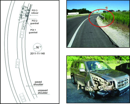
An example of a crash involving a vehicle with one of the advanced modules is NASS/CDS case 2011-11-148. The scene diagram and photographs from the case are shown in . This crash involved a 2009 Ford Escape that was traveling on an entrance ramp to a highway. The vehicle departed the roadway and struck the end terminal of a guardrail on the edge of the paved shoulder. The vehicle rotated clockwise and rolled onto its side. The driver, the only occupant, suffered minor injuries and was not transported to a medical facility.
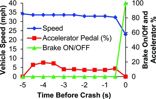
shows the precrash vehicle speed, accelerator pedal, and brake switch status for the vehicle in NASS/CDS case 2011-11-148. The vehicle was traveling at a relatively constant speed prior to the crash with the driver maintaining a speed between 34 and 32 mph. Approximately 0.5 s prior to the crash the driver applied the brakes, slowing the vehicle to 23 mph at the time of impact.
Fig. 3 Precrash vehicle speed, accelerator pedal, and brake switch status for NASS/CDS case 2011-11-148 (color figure available online).
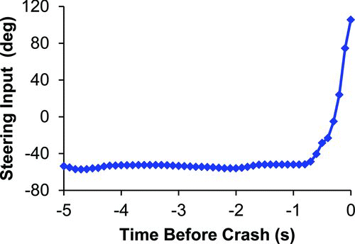
The steering wheel input of the driver in this crash is shown in . A positive steering wheel angle causes a positive yaw, which in this module corresponds to the vehicle rotating counterclockwise. The driver in the crash was steering at an angle between −57 and −52°. At approximately 0.8 s prior to the crash, the driver rapidly turned the wheel counterclockwise in an effort to avoid the impending collision with the guardrail terminal, reaching a maximum steering wheel angle of 105° at the time of the collision.
Reconstruction of Vehicle Trajectories
The goal of the computer model in a SIM is to reconstruct collisions as they occurred and then simulate the crashes with an active safety system to determine benefits. To accomplish the first of these goals, simulations were constructed using the vehicle models with data recorded by the advanced EDRs as inputs to the model as shown in . The simulation software PreScan was used to construct the simulations. PreScan includes a 2-wheeled vehicle handling model. Specifications and modifications to the PreScan vehicle model made in this study are detailed in the following section. The inputs to the simulation were the vehicle specifications, the EDR-recorded precrash vehicle speed, and the EDR-recorded precrash steering wheel input. The simulation outputs were compared to the vehicle precrash yaw rate and accelerations recorded by the EDR but not used to develop the models.
Fig. 5 Process for simulating and validating vehicle trajectory models using advanced EDR data (color figure available online).
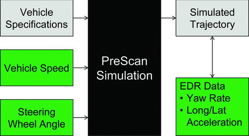
A simple controller was used to manipulate the vehicle steering wheel, throttle, and brake to approximate the EDR-recorded data. The steering wheel input was used as a direct input to the simulation. A proportional-integral controller was used to control throttle and brake to the vehicle model with the difference of the actual and desired vehicle speed (in m/s) as the control signal. The proportional gain of the controller was 100 and the integral gain was 10. The objective of this controller was to match the EDR-recorded vehicle velocity, not to exactly match the brake and throttle inputs. The PreScan vehicle model has a generic engine and powertrain model, which was not modified for different vehicles. In addition, the model was conducted on a flat terrain. Therefore, the EDR-recorded throttle and brake might not necessarily reproduce the desired vehicle speeds due to engine difference and/or elevation changes.
Vehicle Model
The vehicle handling model that is included with the PreScan software is based on a 2-wheeled vehicle; that is, a bicycle model. In addition to the kinematics of the vehicle, the model includes engine, transmission, and gear shifting characteristics. Two models were developed for this study: a 2011 Ford Fusion and a 2011 Ford Escape. These 2 vehicles were the 2 most frequent models that had EDR data available from NASS/CDS cases. Representative vehicle models were constructed using publicly available vehicle specifications and published test results. The main vehicle specifications modified in the vehicle model were vehicle dimensions, curb weight, center of gravity (CG) location, tire diameter, front and rear tire cornering stiffness, and vehicle yaw moment of inertia.
Many of the basic length and weight dimensions were available from the manufacturer, and most of the inertial and tire properties were compiled from other sources. The NHTSA computes a vehicle's static stability factor (SSF) as part of the vehicle's rollover risk for the New Car Assessment Program (NCAP). SSF is the ratio of half the average track width and the CG height. Using the SSF and the results of a dynamic steering test, the NHTSA computes a percentage risk of rollover (NHTSA 2008). This rollover risk is used to compute the vehicle's rollover star rating reported in the NCAP. The static stability factor, and thus the CG height, was computed using the following formula:
shows the parameters used for the Fusion and Escape models. The vehicle's tire size was recorded by the NASS/CDS investigator and was used to estimate the total tire diameter in the model. Front and rear tire cornering stiffness values were estimated categorically from data used by the NASS/CDS investigators to reconstruct impact speeds in some cases (NHTSA Citation1982). Because the model was a 2-wheeled model, the cornering stiffness values in were doubled for the front and rear wheels.
Table 1 Vehicle model parameters for Ford vehicles
The vehicle curb weight was estimated based on the engine and drivetrain indicated by the NASS/CDS investigator. The Fusion either had a 2.0 L V4 or 3.0 L V6 engine (1516 and 1563 kg, respectively) and the Escape had 2.5 L V4 and 3.0 L V6 engines with front- or all-wheel drive (1498 to 1610 kg). The vehicle radius of gyration was estimated as 30 percent of the total vehicle length, an estimate used by NASS/CDS investigators to compute vehicle change in velocity during the crash (Sharma et al. Citation2007). The yaw moment of inertia was derived from the radius of gyration and the vehicle's curb weight.
The vehicle model included in the PreScan software was used as is except for the cornering force model. The PreScan vehicle model originally used a linear tire model where the lateral tire forces were the wheel slip angle multiplied by the tire cornering stiffness. This assumption is valid at low slip angles but not at high slip angles. Instead of a linear model, we used a quadratic approximation of tire force (Jazar Citation2008):
Lane Departure Warning Model
To demonstrate the utility of the reconstruction methods developed in this study, we simulated several departure crashes with advanced EDR data as if the vehicle was equipped with an LDW system. There were crashes from NASS/CDS with advanced EDR data that could have been mitigated by other active safety systems, such as blind spot monitoring or forward collision avoidance systems. We chose to model benefits for LDW because crashes where LDW would activate were the most challenging to reconstruct due to the vehicle traveling off the road. The LDW was delivered when the leading wheel of the vehicle first crossed the lane marking.
Measurements from scene diagrams prepared by the NASS/CDS investigators were used to approximate the crash scenes; that is, road curvature and lane widths. The initial position of the vehicle in the LDW simulation was determined using the simulation trajectory without LDW to match the final impact location and orientation specified by the NASS/CDS investigator.
To model driver variability, 2 types of driver responses were simulated. The steering wheel angle and throttle control were identical to the EDR recorded values until the point where the driver intervened. The first type of driver, a late and fast response, started to steer after a 1.36 s delay after the warning delivery. This reaction time was the largest mean steering reaction time for a driving simulator study with distracted drivers (Suzuki and Jansson Citation2003). After the delay, the late and fast steering driver released the throttle and steered back toward the road at a rate of 262°/s with a maximum steering amplitude of 53°. These steering values were found from the average emergency steering maneuvers performed in an experiment performed on a test track of a distracted driver avoiding an intersection incursion (Mazzae et al. Citation1999). The second type of driver was an early but slow steering driver. The second driver had a reaction time of 0.62 s, a steering rate of 50°/s, and maximum magnitude of 150°. The reaction time was the average of drivers in another driver simulator study with drowsy subjects exposed to an LDW system (Kozak et al. Citation2006).
Results
First, we present the results of validation simulations using all of the advanced EDR data available from NASS/CDS. Next, we use the developed models to demonstrate an estimation of the benefits of LDW systems in fixed object and opposite direction crashes.
Validation of Vehicle Trajectories
Using the EDR steering wheel angle, vehicle speed, and throttle as inputs, baseline PreScan simulations were created. The simulations were validated by comparing the simulation yaw rate, lateral acceleration, and longitudinal acceleration to those recorded by the EDR. Cases were selected from NASS/CDS that had an associated download of an advanced Ford EDR. In total, there were 34 cases with the FordRC6 module from NASS/CDS years 2009 and 2011. We restricted our analysis to the 2 most common vehicle makes: the Ford Fusion and Ford Explorer and their respective mechanical clones the Mercury Milan and Mercury Mariner. There were 13 Fusion/Milan cases and 9 Escape/Mariner modules downloaded from crashes (22 total). The simulation time step was 1 ms. The friction coefficient was assumed to be 1.0.
Table 2 Crash type, off-road travel, and ESC/ABS activation in advanced EDR cases
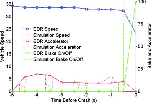
Fig. 6 Precrash speed, accelerator pedal, and brake switch for case 2011-11-148 (color figure available online).
summarizes the crash type and whether the vehicle departed the road, electronic stability control (ESC) activated, or antilock brake system (ABS) activated for the 22 cases with advanced EDRs. Straight crossing path, road departure, and left turn across path opposite direction (LTAP/OD) were the most common scenarios. Off-road travel, ESC activation, and ABS activation were most common in road departure crashes. Rear-end collision could be mitigated by forward collision avoidance systems, such as forward collision warning, brake assist, and autonomous braking. Straight crossing path crashes could be mitigated by vehicle-to-vehicle or vehicle-to-infrastructure systems. Road departure and opposite direction could be mitigated by LDW. The trajectories developed in this section could be used to investigate any one of these technologies in a SIM. The NASS/CDS case information for each of the 22 cases is tabulated in Appendix A (online supplement).
Plots of the complete simulation inputs and results for each case are included as appendices. The Fusion results are in Appendix B and the Escape results in Appendix C (online supplements). In this subsection, we will present example results and discuss the overall results of all simulations.
shows the speed, accelerator pedal, and brake switch status from the EDR and simulation results for case 2011-11-148, the same example case shown in the Methodology section. The model recreates the vehicle speed while approximately following the EDR-recorded accelerator and brake switch status.
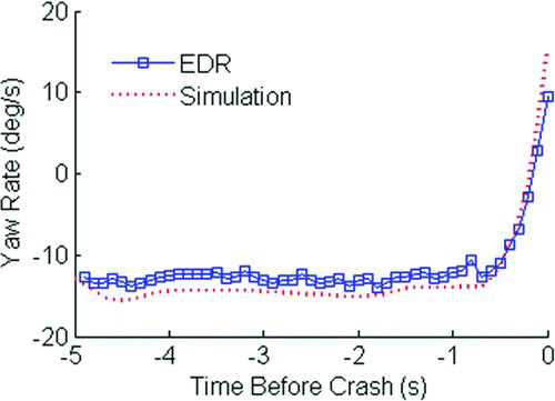
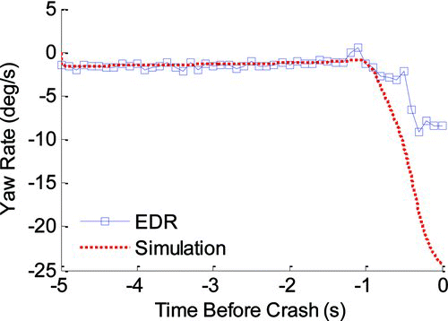
The precrash yaw rate from the EDR and simulation for case 2011-11-148 is shown in . The EDR and simulation yaw rates showed agreement during both the constant and changing steering input. Integrating both to find the total change in angle during the 5-s precrash phase found a difference of 6.6° between the two. The longitudinal and lateral accelerations of the EDR and simulation, shown in the Appendix, also show agreement.
Fig. 7 Precrash yaw rate for EDR and simulation for case 2011-11-148 (color figure available online).
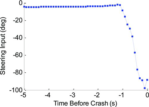
Other simulations did not show good agreement with the recorded EDR, especially when the vehicle departed the roadway. Case 2011-11-149 involved a driver in a 2010 Mercury Milan traveling on a road that curved to the right. The driver was steering insufficiently and the vehicle departed the road to the left, traveled over the roadside surface of grass, and impacted a tree and utility pole. The vehicle was traveling at an approximately constant speed of 47 mph during the precrash phase with the brake switch off for all precrash records. shows the steering input recorded by the EDR for this case.
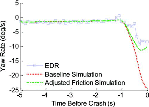
shows the yaw rate for the EDR and simulation for case 2011-11-149. During the steering rate increase during the last second of data, which most likely occurred off the paved road surface, the simulation diverged from the EDR-recorded yaw rate. The vehicle's stability control was not active during the precrash phase as indicated by the EDR. The steering rate and magnitude of this case was similar to other crashes where the vehicle was turning prior to the crash, which showed much better agreement than case 2011-11-149. The only difference between this case and others was that the vehicle left the paved surface.
Fig. 9 Precrash yaw rate for EDR and simulation for case 2011-11-149 (color figure available online).
Overall, the simulations and recorded EDR data matched reasonably. The best agreement was found when both of the following were true: (1) the vehicle remained on the paved surface and (2) ESC did not activate. In the cases modeled, these conditions were true for intersection crashes (left turn across path, straight crossing path) and rear-end collisions. shows the average absolute error of the maximum yaw rate in the simulation compared to the EDR. Departure crashes had high error due to divergence of the simulations during the last, off-road portion of the simulations. The relatively high errors in rear-end collisions are deceiving because there was almost no steering in these 3 crashes. Therefore, small differences in yaw rate magnitude caused disproportionately large errors.
Table 3 Average absolute error in maximum yaw rate in simulations compared to EDR
Yaw rate sensors are prone to bias errors, which appear to have manifested in some of the yaw rate signals recorded by the EDRs. For example, in case 2011-43-051 involving a Fusion, the driver steering input was relatively constant between −4 and −2° for the first second of the precrash record. The yaw rate recorded by the EDR for this case, however, indicates a positive yaw rate, opposite of what is expected. From the scene photographs, the roadway was approximately level and the vehicle stayed on the road until the collision. The model results for this case suggest that it is feasible that the yaw rate could be biased by approximately 2°/s. Integrated over the entire precrash record, a bias of 2°/s would cause an error of 10° in the predicted change in angle. The error in 2011-43-051 is apparent because of the low angle of steering. In other cases with more steering, however, potential bias errors are difficult to discern.
Modification of Surface Friction
The baseline simulations in the previous section had a constant friction coefficient of 1.0. Friction can be greatly reduced on off-road surfaces such as grass, with some experiments finding values as low as 0.2 (Noon Citation1994). The challenge with adjusting the friction coefficient in the simulations is that the point at which the vehicle departed the road is unknown. In case 2011-11-149, the yaw rate and accelerations recorded by the EDR suggest that the vehicle may have left the road approximately 1 s prior to the crash. From measurements based on the scene diagram, the first point of impact was approximately 24 m from the point the vehicle departed the road. Integrating the vehicle speed from the EDR, the vehicle traveled approximately 21.2 m in the last second of the precrash record.
shows the simulation and EDR yaw rates with a surface friction of 0.25 starting in the last second of the simulation. This adjustment in friction appeared to create better agreement between the simulation and EDR, limiting the yaw rate of the vehicle as the driver steered back toward the road.
Lane Departure Warning Benefits
In this section, we demonstrate a methodology of using the reconstructed vehicle trajectories from the previous section to estimate benefits of an LDW system. LDW was chosen as an example system to investigate because these cases were more difficult to reconstruct than other on-road crashes. We chose one fixed object crash, 2011-11-148, and one opposite direction crash, 2011-48-111, that showed good agreement between the simulation and EDR data. Both of these crashes involved vehicles that did not depart the roadway and did not have ESC active prior to the crash.
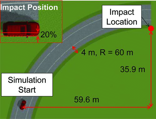
The scene reconstruction in PreScan for case 2011-11-148 is shown in . The model trajectory was used to select an initial position so that the final position of the vehicle was at the impact location. From the damage to the vehicle, we assumed a 20 percent frontal overlap at impact and an impact angle of 0° (see ). The road characteristics were indicated by the NASS/CDS investigator in the case's scene diagram. The radius of curvature of the painted edge line was approximately 60 m and the shoulder was 4 m (2.6 m paved and 1.4 m unpaved).
Fig. 12 Trajectory of right front wheel with and without LDW for case 2011-11-148 (color figure available online).
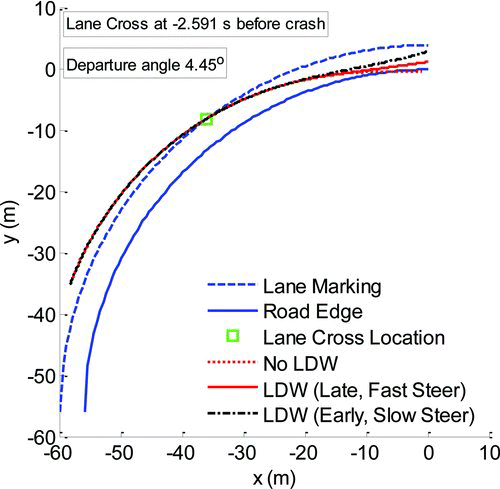
Next, we modeled the precrash phase with an LDW that delivered a warning to the driver when the leading wheel first touched the painted lane line. shows the simulated trajectories of the right front wheel with and without an LDW system. The vehicle's right front wheel crossed the painted lane line 2.6 s prior to the crash with a 4.5° departure angle. With LDW, it is feasible that both a driver with a late and fast response and a driver with an early and slow response could have avoided the collision with the guardrail end.
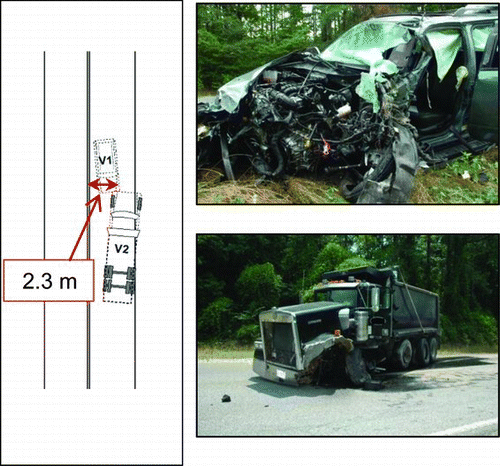
The next case, 2011-48-111, was a head-on crash involving a 2011 Escape striking a Kenworth dump truck. The scene diagram and vehicle damage are shown in . The scene diagram indicated that the investigator measured skid marks on the road attributed to the left front tire of the Escape that corresponded to the collision. This skid mark started 2.3 m from the centerline out of a 3.9 m lane with an estimated angle of impact of 5° with respect to the centerline.
Fig. 14 Vehicle initial position given final impact angles for case 2011-48-111 (color figure available online).
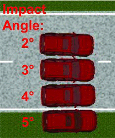
Using the simulated vehicle trajectory, the position of the Escape in its lane 5 s prior to the crash could be estimated. The driver of the Escape was applying a constant steering angle between 2.5 and 2.2° prior to the crash and the total change in angle during the simulation was only 3.8° over a longitudinal distance traveled of 119 m. As a result, the initial location of the vehicle was sensitive to the assumed impact angle, as shown in . For the simulation of LDW benefits, we chose an impact angle of 3.5°, which placed the vehicle CG approximately in the middle of the lane.
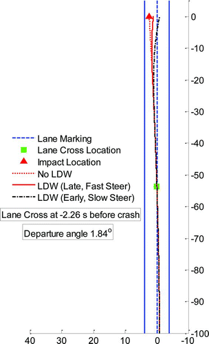
shows the trajectory of the front left wheel with and without an LDW. The Escape departed the lane at a 1.8° angle 2.3 s prior to the crash. The travel speed of the dump truck prior to the crash was unknown; however, the police-reported travel speed was 50 mph. A worst-case scenario for the Escape avoiding the collision would be if the dump truck was traveling in a straight line with its leftmost edge on the centerline. In this simulation, the driver with a late and fast steering response would not avoid the collision with LDW. The driver with an early and slow steering response, however, would be able to avoid the collision. In a SIM, many different driver reactions could be simulated to account for unknown driver reactions to the system. Each simulation could be weighted based upon the likelihood of a driver reacting in a specified manner. These weights would be derived from population averages—for example, of reaction time or steering rate—derived from simulator, naturalistic, or test track experiments.
Discussion
This study has presented a novel reconstruction method for the precrash phase of a collision using advanced EDR data to supplement crash reconstruction data in NASS/CDS. Many previous methods for recreating precrash vehicle movement have had to rely on reconstruction methods that use sources of data such as physical evidence observed by the crash investigator. The advantage of using EDR data is that it records both the actions of the driver and resulting vehicle state prior to the crash.
The simulation of LDW benefits presented in this study is an example of the application of this method and advanced EDR data. One challenge to using the currently available advanced EDR data to estimate fleet-wide benefits of a system is the limited number of cases. Because the advanced steering wheel data used in this study were only available on model year 2009 and later vehicles, we expect an increase in the number of these modules in future years of NASS/CDS. One key to successfully reconstructing the collision from the NASS/CDS and EDR data is a reference point of the vehicle's final position with respect to the road. In the 2 example cases shown here, we were able to use the scene diagrams prepared by the investigators to determine a reference point. Not all scene diagrams, however, will have this information.
The methodology is feasible to be extended to a large number of cases to provide an estimate of fleet-wide benefits. It would take an analyst only several minutes per case to extract the parameters needed for the simulation. After parameters are defined, each simulation runs in several seconds. Given a sample of EDRs representative of the target population available in the future, this method could be extended. One immediate application for this methodology is to use it as a calibration or validation for existing SIMs or driver models. Similar cases simulated as part of a SIM could be compared to the crashes reconstructed using EDR data.
The methodology of using EDR data to simulate real-world collisions could be extended, particularly how the driver and LDW system are modeled. A more advanced driver model could be implemented to better represent drivers’ reactions to a system like LDW. Sensor simulation, including cameras and lighting effects, is an advanced feature of PreScan not used in this study. A more detailed model of an LDW system could be implemented given more detailed specifications.
The relatively straightforward vehicle and terrain model used in this article produced reasonable results compared to the EDR recorded yaw rate, accelerations, and narrative description of the cases. This method could be improved by using a more complex vehicle and terrain model that may handle situations where the current model did not re-create the observed results. The first improvement could be a model of ESC to incorporate into the vehicle model. The precise algorithms used in ESC systems are highly proprietary. This EDR data could be used as validation, however, for a model of ESC. A model of ESC may also be important to investigate driver emergency steering after the LDW is delivered.
The reconstruction approach developed for this study is not limited to use with EDR data and could also be applied to naturalistic driving study data, such as the upcoming Strategic Highway Research Plan 2 (SHRP2) naturalistic data (Antin et al. 2011). Naturalistic driving studies have similar instrumentation—for example, steering wheel angle and yaw rate—which is recorded on advanced EDRs. The EDRs recovered from NASS/CDS have the advantage of all being downloaded from vehicles that were involved in serious, tow-away crashes, whereas serious crashes are scarce in naturalistic data. The approach developed for EDR data in this article could be combined with naturalistic data to create a SIM that evaluated benefits to drivers in departure situations that result in both crashes as well as near-crash events.
The 49 CFR Part 563 regulation was instituted by the NHTSA and is in effect for all vehicles manufactured after September 1, 2012 (NHTSA 2012). The regulation standardizes reporting, accuracy, and precision of measurements for all vehicles that have an EDR that is able to store data. All vehicles that have an EDR must also have a publicly available tool for retrieving the data. Before this regulation, manufacturers were voluntarily providing access to their EDRs via the Bosch CDR tool. The public download tool requirement of the regulation should greatly increase the number of EDRs collected by NASS/CDS investigators. Steering wheel input is only required to be recorded at a sample rate of 2 samples per second and the regulation does not require precrash yaw rate or accelerations to be recorded. The newest Ford EDRs, such as those equipped on the 2013 Ford Taurus, Escape, and Explorer, also record the same type of steering wheel, yaw rate, and acceleration precrash data as the module used in this study. Other manufacturers, such as Chrysler, also are able to record this type of advanced precrash data. Therefore, this type of EDR data is likely to only increase in frequency in future years of NASS/CDS.
Conclusions
In this article, we presented a methodology for recreating vehicle trajectories using advanced EDR data. When executed for a large sample of EDR-equipped vehicles, these precrash vehicle trajectories could be used as the basis for a SIM for benefit estimation for active safety systems. The vehicle handling model used was a 2-wheeled model with parameters collected from publicly available data sources. The steering wheel input and vehicle speeds recorded by the EDR were used as model inputs. The model was validated using the yaw rate and longitudinal and lateral accelerations recorded by the EDR but not used to create the simulations. The resulting model reasonably reproduced the observed yaw rates and accelerations when the vehicle did not depart the road and ESC did not activate. Modifying the surface friction of the environment when the vehicle departed the road produced better results in one case where the vehicle departed the road and ESC did not activate. Finally, we demonstrated a simulation of 2 road departure crashes to estimate benefits of an LDW system. The results of this study showed that this reconstruction method is feasible for the study of active safety systems. The main limitation to immediately implementing a SIM using EDR data is the limited availability of cases. The number of EDRs with advanced precrash data is likely to increase in coming years due to model year availability in the fleet as well as new regulations requiring EDRs, making this a promising method for studying active safety systems in the future.
Appendix.zip
Download Zip (328.8 KB)Acknowledgments
The research team would like to thank Toyota Motor Corporation, Toyota Motor Engineering & Manufacturing North America, Inc., and the Toyota Collaborative Safety Research Center (CSRC) for funding this research.
© Kristofer D. Kusano, Rini Sherony, and Hampton C. Gabler
References
- Abele , J , Kerlen , C Krueger , S . Exploratory Study on the Potential Socio-economic Impact of Introduction of Intelligent Safety Systems in Road Vehicles Tetlow , , Germany VDI/VDE Innovation Project; 2005
- Antin , J , Lee , S , Hankey , J M and Dingus , T A . 2011 . “ Design of the I-Vehicle Driving Behavior and Crash Risk Study. Washington, DC: Transportation Research Board ” . SHRP 2 Report S2-s05-RR-1 .
- Bayly , M , Fildes , B , Regan , M and Young , K . 2007 . Review of Crash Effectiveness of Intelligent Transportation Systems Brussels , European Commission TRACE Project Deliverable D4.1.1
- Bosch . 2013 . EDR News and Information . Available at http://boschdiagnostics.com/testequipment/cdr/Pages/CDRHome.aspx. Acce- ssed May 20
- Carter , A A , Burgett , A , Srinivasan , G and Ranganathan , R . safety impact methodology (SIM): evaluation of pre-production systems . Paper presented at: 21st International Conference on the Enhanced Safety of Vehicles , Stuttgart , , Germany June 15–18
- Funke , J , Srinivasan , G , Ranganathan , R and Burgett , A . Safety impact methodology (SIM): application and results of the Advanced Crash Avoidance Technologies (ACAT) Program . Paper presented at: 22nd International Conference on the Enhanced Safety of Vehicles , Washington , DC June 13–16
- Gabler , H C and Hinch , J . Feasibility of using event data recorders to characterize the pre-crash behavior of drivers in rear-end collisions . Paper presented at: 21st International Conference on the Enhanced Safety of Vehicles , Stuttgart , , Germany June 15–18
- Gordon , T , Sardar , H Blower , D . 2010 . Advanced Crash Avoidance Technologies ACAT Program—Final Report of the Volvo– Ford_UMTRI Project: Safety Impact Methodology for Lane Departure Warning—Method Development and Estimation of Benefits , National Washington , DC : Highway Traffic Safety Administration . DOT HS 811 405
- Isaksson-Hellman , I and Lindman , M . 2012 . The effect of a low-speed automatic brake system estimated from real life data . Ann Adv Automot Med. , 56 : 231 – 240 .
- Jazar , RN. 2008 . Vehicle Dynamics: Theory and Applications , New York , NY : Springer .
- Kozak , K , Pohl , J Birk , W . Evaluation of lane departure warnings for drowsy drivers . Paper presented at: Human Factors and Ergonomics Society 50th Annual Meeting , San Francisco, CA October 16–20
- Kusano , K D and Gabler , H C . 2011 . Method for estimating time to collision at braking in real-world, lead vehicle stopped rear-end collisions for use in pre-crash system design . SAE Int J Passeng Cars - Mech Syst , 4 ( 1 ) : 435 – 443 .
- Mazzae , E N , Barickman , F , Baldwin , G HS and Forkenbrock , G J . 1999 . Driver crash avoidance behavior with ABS in an intersection incursion scenario on dry versus wet pavement , Warrendale , PA : SAE International . Paper Number 1999-01-1288
- National Highway Traffic Safety Administration (NHTSA). 49 CFR Part 563 . 2012 . Event Data Recorders—Final Rule . Last updated August 13 National Archives and Records Administration Available at: http://www.ecfr.gov/cgi-bin/text-idx?c=ecfr&SID=e4f1485bb6f2dd7972fd0c80a4870113&rgn=div5&view=text&node=49:6.1.2.3.31&idno=49. Accessed April 22, 2013
- National Highway Traffic Safety Administration . 1982 . CRASH3 User's Guide and Technical Manual , Washington , DC : National Highway Traffic Safety Administration . DOT HS 805732
- National Highway Traffic Safety Administration (NHTSA) .
- National Highway Traffic Safety Administration . 2008 . Consumer Information; New Car Assessment Program; notice . Federal Register. , 73 ( 134 ) : 40016 – 40050 .
- Noon , RK. 1994 . Engineering Analysis of Vehicular Accidents , Boca Raton , FL : CRC Press .
- Sharma , D , Stern , S , Brophy , J and Choi , E . An overview of NHTSA's crash reconstruction software WinSmash . Paper presented at: 17th International Enhanced Safety of Vehicle's Conference , Lyon , , France June 18–21
- Suzuki , K and Jansson , H . 2003 . An analysis of driver's steering behavior during auditory or haptic warnings for designing of lane departure warning system . JSAE Rev , 24 ( 1 ) : 65 – 70 .
- Van Auken , R M , Zellner , J W Chiang , D P . 2011 . Advanced Crash Avoidance Technologies (ACAT) Program—Final Report of the Honda-DRI Team: Vol 1. Executive Summary and Technical Report , Washington , DC : National Highway Traffic Safety Administration . DOT HS 811 454A
