 ?Mathematical formulae have been encoded as MathML and are displayed in this HTML version using MathJax in order to improve their display. Uncheck the box to turn MathJax off. This feature requires Javascript. Click on a formula to zoom.
ABSTRACT
Objective: In car crashes, the passenger compartment deceleration significantly influences the occupant loading. Hence, it is important to consider how each structural component deforms in order to control the passenger compartment deceleration. In frontal impact tests, the passenger compartment deceleration depends on the energy absorption property of the front structures. However, at this point in time there are few papers describing the components' quantitative contributions on the passenger compartment deceleration. Generally, the cross-sectional force is used to examine each component's contribution to passenger compartment deceleration. However, it is difficult to determine each component's contribution based on the cross-sectional forces, especially within segments of the individual members itself such as the front rails, because the force is transmitted continuously and the cross-sectional forces remain the same through the component.
Method: The deceleration of a particle can be determined from the derivative of the kinetic energy. Using this energy-derivative method, the contribution of each component on the passenger compartment deceleration can be determined. Using finite element (FE) car models, this method was applied for full-width and offset impact tests. This method was also applied to evaluate the deceleration of the powertrain. The finite impulse response (FIR) coefficient of the vehicle deceleration (input) and the driver chest deceleration (output) was calculated from Japan New Car Assessment Program (JNCAP) tests. These were applied to the component's contribution on the vehicle deceleration in FE analysis, and the component's contribution to the deceleration of the driver's chest was determined.
Result: The sum of the contribution of each component coincides with the passenger compartment deceleration in all types of impacts; therefore, the validity of this method was confirmed. In the full-width impact, the contribution of the crush box was large in the initial phases, and the contribution of the passenger compartment was large in the final phases. For the powertrain deceleration, the crush box had a positive contribution and the passenger compartment had a negative contribution. In the offset test, the contribution of the honeycomb and the passenger compartment deformation to the passenger compartment deceleration was large. Based on the FIR analysis, the passenger compartment deformation contributed the most to the chest deceleration of the driver dummy in the full-width impact.
Conclusions: Based on the energy-derivative method, the contribution of the components' deformation to deceleration of the passenger compartment can be calculated for various types of crash configurations more easily, directly, and quantitatively than by using conventional methods. In addition, by combining the energy-derivative method and FIR, each structure's contribution to the occupant deceleration can be obtained. The energy-derivative method is useful in investigating how the deceleration develops from component deformations and also in designing deceleration curves for various impact configurations.
Introduction
Occupant protection is one of the most important issues in the development of a car. The injury risks to the occupant depend on the deceleration and the intrusion of the passenger compartment. The offset deformable test (UN R94) was introduced and the structural integrity of the passenger compartment had been the first priority in ensuring the survival space of the occupants (Faerber Citation2007). However, Johannsen et al. (Citation2013) showed that currently the compartment strength of smaller cars is high enough, so the acceleration of the passenger compartment for smaller cars has a higher priority in improving occupant protection. Accident data also show that cars undergoing a crash with a large overlap and hence high deceleration make up a significant portion of all accidents and that the seat belt is a major cause of chest injury among elderly people in these collisions (Edwards et al. Citation2013). These results indicate that a full-width test where the deceleration of the passenger compartment is high and a large loading is applied on the occupants is important. The full-width test has been introduced into UN Regulation 137 and the Euroopean New Car Assessment Program. The deceleration pulse and the performance of the restraint systems influences chest injury measures significantly in this type of crash.
The downsizing of cars is becoming increasingly important in light of the recent focus on improving fuel efficiency. However, in general, the impact severity does not depend on the car mass in the full-width rigid barrier test because this test replicates the scenario of the same model of cars colliding with each other. However, the deceleration of the passenger compartment of minicars tends to be higher than other cars in full-width rigid barrier tests because the length of the front end of the car is limited in minicars (Mizuno et al. Citation2013). Thus, controlling and optimizing the energy absorption of a car's front structure is necessary, particularly for small cars. Because the crash pulse affects the occupant injury risks, the effect of the crash pulse shape on occupant loading has been examined in many studies. It has been shown that the occupant experiences a smaller acceleration from a front-loaded crash pulse (that is, a crash pulse in which the higher accelerations occur early in the pulse duration) compared to a rear-loaded crash pulse (Huang Citation2002). A crash pulse that has been optimized theoretically to minimize the acceleration of the occupant has been constructed by Wu et al. (Citation2002). For a realistic design of vehicle structures, there are some studies in which the sheet metal thicknesses of the front structures were optimized with respect to the target function to minimize vehicle deceleration, intrusion, dummy injury measures, and weight (Fang et al. Citation2005; Liao et al. Citation2008).
Computer-aided engineering is an indispensable tool for vehicle development, and many crashworthiness simulations are conducted using finite element method (FEM). There are few papers that discuss a method of designing the deceleration of the passenger compartment from the deformations of various components, considering the front structures and the passenger compartment as a system instead of individual components. Generally, the cross-sectional forces of the structures are used to control the acceleration of the passenger compartment. The deceleration of the passenger compartment can be expressed by the sum of the forces applied to the firewall (Sekine et al. Citation2008; Toyoma et al. Citation1992). To control the deceleration of the passenger compartment as influenced by each component, the vehicle deceleration–displacement diagram can be used (Song et al. Citation2015). To design the vehicle deceleration pulse is to sum up the cross section forces of the components on the deceleration–displacement curve. However, force paths to the compartment should be understood for prerequisite. Krusper (Citation2014) proposed a relative equivalent energy displacement method based on the cross-sectional force to evaluate the efficiency of the front rails in absorbing energy in various crashes. However, it is still difficult to determine the contribution of each segment of a component based on the cross-sectional force because the force is transmitted continuously through longitudinal structures and the cross-sectional forces remain the same through the structure.
In this research, a new method was developed based on the derivative of energy to understand how the individual structures, as well as the individual segments of each structure, contribute to deceleration of the passenger compartment. In this method, the mechanical energy calculated from FEM is differentiated with respect to time or displacement to determine the structural components' contribution to deceleration of the passenger compartment. The deformations of each structure affect the deceleration of the passenger compartment as well as the loading on the occupant. There are few studies that show the relationship between the components' deformation and occupant deceleration. To predict the occupant deceleration under various vehicle deceleration pulses, a finite impulse response (FIR) can be applied (Eppinger and Chan Citation1981; Huang Citation2002). From the energy-derivative method, the vehicle deceleration can be broken down into the contribution from each component. Hence, in this study, FIR was used to evaluate how the vehicle deceleration generated by each structure affects occupant deceleration.
Method
Derivation of energy-derivative method
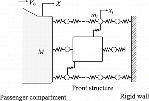
shows the spring–mass model used to represent the front end structures in a frontal impact. The initial velocity of vehicle is V0. The masses, velocities, and internal energy of a component i (1, …, n) are mi, vi, and Ui, respectively. The mass, displacement, velocity, and internal energy of the passenger compartment are M, X, V, and U. Because the mechanical energy with respect to time is conserved until the maximum displacement of the passenger compartment (loading phase) is attained, the following equation is developed:
(1)
(1)
The change in kinetic energy of the passenger compartment is expressed as
(2)
(2) where Ei = (1/2)miv2i + Ui is the mechanical energy of component i. Differentiating EquationEquation 2
(2)
(2) with time, we obtain
(3)
(3)
Hence, the deceleration of the passenger compartment is expressed as
(4)
(4)
Using dX = Vdt, EquationEquation 4(4)
(4) can also be expressed as follows:
(5)
(5)
The contribution of component i to the deceleration of the passenger compartment Ai can be defined as
(6)
(6)
In this study, this method used to calculate the contribution of a component on the deceleration of the passenger compartment based on energy is called the energy-derivative method.
The contribution of a component on the deceleration of the passenger compartment also can be expressed as
(7)
(7)
The force Fi of a component i is composed of both inertial force and deformation force and can be expressed using the mechanical energy Ei.
(8)
(8)
Substituting EquationEquation 8(8)
(8) into EquationEquation 7
(7)
(7) , we obtain
(9)
(9)
The physical meaning of the contribution of a component on the deceleration of the passenger compartment Ai is the ratio of work done by the component per unit time to the momentum of the passenger compartment.
To design the shape of the crash pulse, a deceleration–displacement curve is used. Considering the integral of deceleration with displacement, using adx = (dv/dt)dx = vdv, we obtain
(10)
(10)
The area under the deceleration–displacement curve during the loading phase is constant. Hence, the sum of the contribution of components to the vehicle's deceleration is constant, and a large contribution of a component will lead to a smaller contribution from the other components. In this study, the deceleration–displacement curve was used to examine the effect of each component on deceleration of the passenger compartment.
Crash simulation using FEM
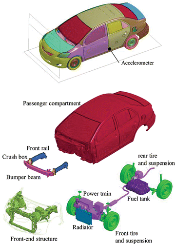
The mechanical energy of each structure can be calculated by FEM. shows the finite element model of a small passenger car used in this study. This car model was developed by the National Crash Analysis Center (Citation2011) and released by the NHTSA (Citationn.d.). The model has about 1.49 million nodes and 1.52 million elements. The general purpose nonlinear dynamic analysis code LS-DYNA (Livermore Software Technology Corporation; Livermore, CA; Hallquist Citation2014) was used. Using this car model, a full-width impact and offset impact analyses were carried out as shown in Figure A1 (see online supplement). In the full-width impact simulation, the initial velocity of the car was 56 km/h. The barrier and the road surface were defined as rigid bodies. The total mass of the model was 1,092.5 kg, and no occupant dummies were seated. In the offset deformable barrier (ODB) impact simulation, the initial velocity of the car was 64 km/h. The honeycomb model developed by Livermore Software Technology Corporation (Citation2014) was used. The deceleration of the passenger compartment during the simulation was measured by an accelerometer at the bottom of the B-pillar on the driver side (left side).
Each component's contribution on the passenger compartment deceleration was determined by Ai = −(1/MV)(dEi/dt) (see EquationEquation 6(6)
(6) ). In the finite element (FE) analysis, the time history of the internal energy and the kinetic energy of each part were obtained. Hence, the mechanical energy of an arbitrary structural group or component can be obtained by adding the energy of the several parts that constituted the group. In this study, the car model was divided into several groups (). The mass M of the passenger compartment including the interior parts was 584.6 kg, and each group's contribution to the passenger compartment's deceleration was calculated. These contributions were expressed in the form of acceleration and plotted in the deceleration–displacement diagram of the passenger compartment. In order to remove the high-frequency content of the acceleration pulse, a filtering processing was performed using a low-pass filter of Society of Automotive Engineers channel class 60 Hz.
In the energy-derivative method, the contribution of the components to the deceleration of an arbitrary component can also be calculated. In this study, the contribution of the components to the deceleration of the powertrain was also examined to understand how the powertrain decelerated. The mass of the powertrain was 164.5 kg. An accelerometer was installed on the engine block to measure the deceleration of the powertrain.
Finite impulse response
The FIR is a transfer function based on the digital convolution method (Eppinger and Chan Citation1981). The relationship between a system input and a predicted output described by the FIR coefficient can be calculated as
(11)
(11) where
is the predicted output at time point n, h(m) is the FIR coefficient at point m, and x(n − m) is the system input at a discrete point n − m. In a frontal impact, the system input, FIR coefficient, and predicted output are the vehicle deceleration, the transfer function depending on the restraint system, and the occupant's deceleration, respectively. Because the acceleration of the passenger compartment is the sum of the contribution of each component (EquationEquation 4
(4)
(4) ), the occupant deceleration
as a function of the component's contribution (xi) can be expressed as
(12)
(12)
Note that . In this study, the FIR coefficient h(m) was calculated from the car's deceleration (input) and the forward deceleration of the Hybrid III driver dummy's chest (output) in a full-width test (Japan New Car Assessment Program; JNCAP) for the same car model as in the FE simulation (Figure A2, see online supplement). Then, the contribution of each component obtained in the full-width FE simulation Ai was substituted into xi in EquationEquation 12
(12)
(12) and the occupant deceleration
by each component was calculated.
Results
Full-width impact simulation
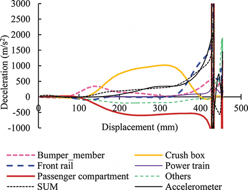
A graph of the total energy and its constituents (kinetic energy, internal energy, sliding energy, and hourglass energy) is shown in Figure A3 (see online supplement). The sliding energy and the hourglass energy were small compared to the internal energy. In this research, the sliding energy was excluded when calculating the contributions of the components, whereas the hourglass energy was included as part of the internal energy of each component. The contribution of each component to the passenger compartment deceleration was calculated using FEM as shown in . The contribution of the bumper beam, crush box, front rail, and passenger compartment deformation were extracted and are shown in Figure A4 (see online supplement), along with the deformation mode of these structures. When the front end of the car initially makes contact with the rigid wall, the bumper beam absorbs the energy, which leads to deceleration in the passenger compartment. After the bumper beam deformed, the contribution of the crush box increased. In this car model, the contribution of the crush box was the largest contributor to the passenger compartment deceleration in initial phase of impact. After the crush box collapsed, the contribution of the front rail became significant. In the final phase, the deceleration of the passenger compartment increased due to deformation of the passenger compartment itself. This is mainly due to deformation of the dash panel and the A-pillar.
Figure 3. Contribution of structural components to deceleration of the passenger compartment in full-width impact test.
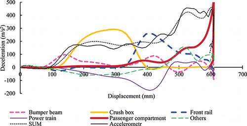
Figure A5 (see online supplement) shows the contribution of the powertrain to deceleration of the passenger compartment. At a displacement of around 400 mm from the front of the car, the powertrain has a negative contribution due to the acceleration component caused by inertial force. Then the powertrain components made contact with the suspension member from which the contribution became positive.
Powertrain's deceleration
The contribution of other components on the powertrain's deceleration is shown in the deceleration–displacement diagram (). The contribution of some components around the engine compartment is extracted and shown in Figure A6 (see online supplement) together with the deformation. The bumper beam, crush boxes, and front rails, which are located in front of the engine mounts, were crushed by the inertia force of the power train and also have positive contribution to the powertrain's deceleration when deforming and absorbing energy. The radiator was sandwiched between the rigid wall and the powertrain, and it absorbed sufficient energy to provide the positive contribution to the powertrain's deceleration. On the other hand, because the suspension frame and the passenger compartment collided against the powertrain from the rear, they provided a negative contribution (acceleration).
ODB simulation
The contribution of car components and the honeycomb barrier are shown in the deceleration–deformation diagram (). In the ODB impact, the passenger compartment deceleration was primarily due to the energy absorption of the honeycomb barrier. The contribution of the passenger compartment due to its own deformation increased around the region of maximum displacement of the car (Figure A7, see online supplement). On the other hand, the contribution of the crush box and the front rail, which contributed significantly in the full-with frontal crash, was small in this ODB simulation.
Figure 5. Contribution of structural components to deceleration of the passenger compartment in ODB crash test.
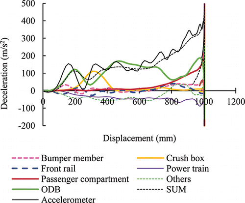
The internal energy of the ODB honeycomb in the FE model was calculated to be 59.5 kJ, which accounts for 35% of the initial kinetic energy of the small car (172.6 kJ). As shown in EquationEquation 10(10)
(10) , the area under the deceleration–displacement curve is the internal energy per unit mass. The internal energy of the ODB honeycomb calculated from this area under the ODB honeycomb's curve in multiplied by the passenger compartment mass (584.6 kg) was also 59.3 kJ.
Occupant dummy's deceleration
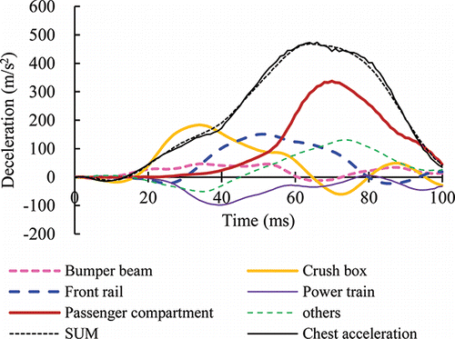
The FIR coefficient calculated from the vehicle's deceleration and the dummy's deceleration in the full-width test (Figure A2) was applied to the contribution of each component on the deceleration of the passenger compartment in the full-width impact simulation (), and the contribution of each component to the chest deceleration of the driver dummy was obtained (). The contribution to the chest deceleration of the dummy starts from components in the front of the car and moving rearwards, first by the bumper beam, followed by the crush box and then the front rails. The chest acceleration becomes maximum due to the final phase of the compartment deceleration. Thus, the compartment deformation has the largest effect on chest acceleration.
Discussion
In this research, a new energy-derivative method was developed to determine the contribution of the components to passenger compartment deceleration. The time history of the mechanical energy of each component required for this method can be calculated from crash simulations using FEM. This method is simpler and is able to achieve more consistent results than the conventional method of analysis using the cross section force to design and control the passenger compartment deceleration.
By applying this method to the full-width impact simulation, the sum of the contribution of components was consistent with the passenger compartment deceleration; therefore, the validity of this method was confirmed. By using the energy-derivative method, we can examine the contribution of the components to the passenger compartment at different times during the crash sequence (Figure A3): the bumper beam, the crush box, and the front rails absorbed the impact energy sequentially starting from the front of the car and moving rearwards. In the deceleration–displacement diagram, the influence of the inertial forces is represented by a negative contribution, such as in the case of the powertrain (Figure A4). Thus, by using this method, it is possible to examine the influence of a component not only from the deformation forces but also from the inertial forces.
The energy-derivative method was also applied to the ODB simulation (). Before the car had a displacement of 900 mm, the honeycomb barrier provided the largest contribution to the car's deceleration, and the contribution of the car structures was minimal. After 900 mm, the contribution of the passenger compartment due to its deformation increased rapidly: the ODB bottomed out and the passenger compartment started to deform. For this situation, not only the contribution of the vehicle structures but even the contribution of the honeycomb barrier also can be obtained. In , the ODB contributes a large portion to the passenger compartment (584.6 kg). One reason is that the crush box and the front rail at the same side of the impacted location did not collapse enough and hence did not absorb a large amount of energy compared to that during the full-width rigid barrier test (Figure A7). Another reason is probably that the car structures have their own masses and absorb their own kinetic energy, whereas the ODB honeycomb is light and only absorbs internal energy with its deformation.
This shows that the energy-derivative method can be applied to various crash configurations, including car-to-car collisions. It is expected that this method can be used to investigate the structural interaction and stiffness matching in car-to-car collisions. Though the evaluation of structural interaction and stiffness matching is complex and difficult, the energy-derivative method can evaluate these influences objectively based on the contribution to passenger compartment deceleration. However, the energy-derivative method in this study was based on the energy conservation law in a one-dimensional spring–mass system. Therefore, it is not possible to analyze the passenger compartment deceleration undergoing a large rotation, which occurs in a small overlap or an oblique crash test. Hence, further study is needed to extend the energy-derivative method in a three-dimensional analysis that includes vehicle rotation.
There are a few studies that investigated how the deformation of each structure affects occupant loading. The combination of FIR and the contribution of the components in the energy-derivative method was useful in investigating how the deformation of each structure affects dummy chest deceleration. From the energy-derivative method, it was shown that the deformation of the passenger compartment strongly affected the deceleration of the passenger compartment in the final phase of the full and offset impact tests; from the FIR analysis, this deformation of the passenger compartment has the largest effect on the occupant loading. It would be difficult to reduce the strength of the passenger compartment because it relates to the survival space. Therefore, controlling the passenger compartment deceleration through deformation of the various components of the car is important. In this study, the combination of the energy-derivative method and the FIR was used to examine the contribution of each part on the chest deceleration of the occupant since no dummy model was seated in this FE model. In principle, the energy-derivative method can be applied to the thoracic spine or the head of the dummy, and the contributions of the vehicle structures and the restraint systems to the deceleration of the thoracic spine or the head can be determined.
This study presented a new method that can be used to control the deceleration of the passenger compartment based on the derivative of the energy of each component. From our point view, this method is a strong tool that can be used to design the vehicle deceleration pulse shape based on structural deformation. Compared to previous studies, this method has the following features and advantages:
| • | This method is simple and easily identifies the contributions of each component to passenger compartment deceleration. It can be used directly to design the deceleration shape of the passenger compartment in the deceleration–displacement diagram. | ||||
| • | From a physical point of view, this method shows that the passenger compartment's deceleration is related to the derivative of the energy of the components. | ||||
| • | This method has the potential to be used in analyzing situations where deceleration is a key parameter; for example, occupant deceleration, acceleration of the pedestrian's head, etc. | ||||
In addition, because this method is compatible with computer-aided engineering, this method is expected to be combined with other optimization tools to identify which structural part effectively reduces the deceleration of the passenger compartment or the occupant's injuries. Moreover, regardless of how the structures were optimized previously by varying the thickness or shape of the structures, we will be able to understand how the energy of each structure changes to reduce deceleration of the passenger compartment after the optimization of these structures based on the energy-derivative method.
Appendix
Download MS Word (1.7 MB)References
- Edwards MJ, Cuerden RW, Price J, et al. Estimation of the benefits for potential options to modify UNECE Regulation No. 94 to improve a car's compatibility. Paper presented at: 5th International Conference on ESAR; September 7–8, 2013; Hannover, Germany.
- Eppinger R, Chan HS. Thoracic Injury Prediction via Digital Convolution Theory. 25th Stapp Car Crash Conference, September 28–30, 1981; San Francisco, CA. SAE Paper No. 811010; 1981.
- Faerber E. EEVC approach to develop test procedure(s) for the improvement of crash compatibility between passenger cars. Paper presented at: 20th International Conference on Enhanced Safety of Vehicles; June 18–21, 2007; Lyon, France.
- Fang H, Rais-Rohani M, Liu Z, Horstemeyer M. A comparative study of metamodeling methods for multiobjective crashworthiness optimization. Comput Struct. 2005;83:2121–2136.
- Halliquist J.O. LS-DYNA Keyword User's Manual R7.1. Livermore Software Technology Corporation, San Francisco, CA; 2014.
- Huang M. Vehicle Crash Mechanics. Boca Raton, FL: CRC Press; 2002.
- Johannsen H, Adolph T, Edwards M, Lazaro I, Versmissen T, Thomson R. Proposal for a frontal impact and compatibility assessment approach based on the European FIMCAR Project. Traffic Inj Prev. 2013;14:S105–S115.
- Krusper A. Structural Interaction between Vehicles [thesis]. Chalmers University of Technology; 2014.
- Liao X, Li Q, Yang X, Li W, Zhang W. A two-stage multi-objective optimisation of vehicle crashworthiness under frontal impact. Int J Crashworthiness. 2008;13:279–288.
- Livermore Software Technology Corporation. LSTC barrier models. 2014. Available at: http://www.lstc.com/products/models/barriers. Accessed February 25, 2017.
- Mizuno K, Arai Y, Hosokawa N, Hollowell W. The crashworthiness of minicars in frontal impact tests. Paper presented at: 23th International Conference on Enhanced Safety of Vehicles; May 27–30, 2013; Seoul, Korea.
- National Crash Analysis Center. Development and Validation of FE Model for 2010 Toyota Yaris Passenger Sedan. Ashburn, VA: The George Washington University, Virginia Campus. Technical Summary 2011-T-001; 2011.
- NHTSA. Crash simulation vehicle models. n.d. Available at: https://www.nhtsa.gov/crash-simulation-vehicle-models. Accessed: February 25, 2017.
- Sekine Y, Takahashi H, Hayamizu D, Kawamoto D, Nakagawa D. Compatibility between sports-utility vehicles and sedan-type vehicles. Int J Crashworthiness. 2008;13:551–558.
- Song L, Fender J, Duddeck F. A semi-analytical approach to identify solution spaces for crashworthiness in vehicle architectures. Paper presented at: 24th International Conference on Enhanced Safety of Vehicles; June 8–11, 2015; Gothenburg, Sweden.
- Toyama A, Hatano K, Murakami E. Numerical Analysis of Vehicle Crash Phenomena. SAE International Congress and Exposition, Detroit, MI; 1992. SAE Paper 920357; 1992.
- Wu J, Nusholtz G, Bilkhu S. Optimization of vehicle crash pulses in relative displacement domain. Int J Crashworthiness. 2002;7:397–414.

