
Abstract
Objective
The goal of this study was to evaluate the effect of axial compression, employed with a follower-load mechanism, on the response of the lumbar spine in flexion and extension bending. Additional goals include measurement of both the kinetic (stiffness) and kinematic (deformation distribution) responses, evaluating how the responses vary across specimens, and to develop response corridors that can be used to evaluate human body models (HBMs) and anthropomorphic test devices (ATDs).
Methods
Seven mid-sized male adult lumbar spines (T12-S1) from postmortem human surrogates were tested in subinjurious flexion and extension bending with 0, 900, and 1800 N of superimposed axial compression. Tests were performed in load-control with a 6-DOF robotic test system that applied pure flexion and extension moments to the specimens, and axial compression was directed along the spine’s curvature via a follower load mechanism powered by force-controlled linear actuators. Load-deformation response data were captured and used to characterize the kinetic response of the lumbar spine in flexion/extension, and how it varies with axial compression. Individual vertebral kinematics were captured using 3D motion capture and the data was used to illustrate the distribution of bending deformation across each intervertebral joint of the spine, as well has how that distribution changes with axial compression. These response data were used to develop elliptical path-length parameterized response corridors for surrogate biofidelity evaluation.
Results
The lumbar spine was found to be generally stiffer in extension than in flexion, but this difference decreased with increasing axial compression. The lumbar spine exhibited a nonlinear kinetic (moment vs. angle) response in flexion that became more linear and stiffer with the addition of axial compression. In flexion without axial load, the majority of the bending deformation occurred at the L5-S1 joint, whereas in extension, deformation was more evenly distributed across the different intervertebral levels, but the locus of deformation was located in the mid-proximal lumbar at L2-L3.
Conclusions
The superposition of axial compression in the lumbar spine affects the kinetic and kinematic response of the lumbar spine in flexion and extension. The response data and approach detailed in this study permit better assessment of ATD and HBM biofidelity.
Introduction
Historically, while the driving task limited the amount of seatback recline possible for drivers, vehicle manufactures have instructed all occupants to maintain an upright restrained posture while riding in vehicles to maximize the benefits provided by the seat and occupant restraint systems. However, the introduction of autonomous driving systems (ADS) has resulted in automotive industry interest in the preferences of vehicle occupants to utilize nonstandard vehicle seating positions (Koppel et al. Citation2019, Östling and Larsson Citation2019, Reed et al. Citation2020). In anticipation of novel seating postures in autonomous vehicles, there has been substantial research to study the injuries to occupants with reclined seatbacks that are positioned far away from the traditional vehicle instrument panel and knee bolster. This arrangement may require occupant restraint to be managed solely with the seat belt and seat. Yet in frontal crashes with reclined occupants and strong pelvis restraint, human body model (HBM) simulations have suggested that the lumbar spine would be subjected to simultaneously high compression and flexion loading (Gepner et al. Citation2019, Gepner et al. Citation2020, Rawska et al. Citation2019, Rawska et al. Citation2020, Mroz et al. Citation2020). In these simulations, the reclined orientation of the torso and the pelvic restraint offered by the seat and lap belt initially result in lumbar compression. If a shoulder belt force limiter is engaged, the upper torso may then translate forward, potentially bringing the head and upper torso forward of the pelvis/H-point. Such torso kinematics cause flexion of the lumbar spine, which becomes superimposed on the compression. This compression/flexion loading mechanism in frontal crashes with reclined occupants has also been illustrated in sled tests with postmortem human surrogates (PMHSs) that sustained lumbar spine fractures characteristic of compression/flexion loading (Richardson et al. Citation2020a, Richardson et al. Citation2020b), and with anthropomorphic test devices (ATDs) that measured high magnitude compression and flexion loads (Östling et al. Citation2021).
Previous studies showed that the mechanical response or “stiffness” of lumbar spine functional spinal units (FSUs) (two vertebrae) in bending and in shear is affected by superposition of axial compressive loads (Adams and Dolan Citation1996, Adams and Dolan Citation2011, Li et al. Citation2011, Lin et al. Citation1978, Yang et al. Citation1985). While these data provide kinetic response information for FSUs, they lack a description of how spinal flexion kinematics are distributed across the individual vertebral motion segments of the lumbar spine. While such information could be obtained from experiments where the entire lumbar spine (more than two-vertebra FSUs) is subjected to combined compression and flexion, the lumbar spine has been shown to be unstable and eventually buckle under compressive loads (∼88 N, Crisco et al. Citation1992) far lower than those experienced physiologically (600–1000 N, Nachemson Citation1981) due to its lordotic curvature. To address this problem, Patwardhan et al. (Citation1999) first introduced the “follower load” loading mechanism to direct the compressive force along a path that approximates the tangent of the spine’s curvature, which substantially increased the compressive load-carrying capacity of the spine. They accomplished this by attaching cable guides bilaterally to the L2 through L5 vertebral bodies with the L1 body held in the superior potting cup, then fed steel cables through the cable guides and attached an anchor weight sufficient to impose 1200 N of compressive follower load. While several additional studies have employed the use of a follower load mechanism to evaluate lumbar spine response to and effect of axial compression (Fry et al. Citation2014, Gaffey et al. Citation2010, Goel et al. Citation2006, Mageswaran et al. Citation2012, Patwardhan et al. Citation2003, Rohlmann et al. Citation2001, Renner et al. Citation2007, Wilke et al. Citation2003), these studies have used low magnitude loading to investigate sources for low-back pain. No previous studies have used a follower-load mechanism to investigate the response of the lumbar spine with loading magnitudes relevant for occupant crash/traumatic injury situations.
Since HBM simulations and testing with ATDs and PMHSs have indicated the lumbar spine is loaded in flexion bending combined with compression in reclined occupant frontal crashes, response data for the human lumbar spine are needed to evaluate the biofidelity of ATDs and HBMs. As a result, the goal of this study was to evaluate the effect of axial compression, employed with follower-load mechanisms, on the response of the lumbar spine in flexion and extension bending. Additional goals included measuring both the kinetic (stiffness) and kinematic (deformation distribution) responses, evaluating how the responses vary across specimens, and developing response corridors that can be used to better evaluate HBMs and ATDs.
Methods
Specimen preparation
Seven fresh-frozen, previously untested male postmortem human surrogate (PMHS) lumbar spine specimens (T10-Sacrum), which were free from preexisting injuries, deformities, or significant ossification and degeneration were obtained, stored, prepared, and tested in accordance with the ethical guidelines established by the Human Usage Review Panel of the National Highway Traffic Safety Administration (NHTSA) and all procedures were reviewed and approved by the University of Virginia Institutional Review Board-Human Surrogate Use Committee (average: 40 years, 177 cm, 80 kg, 25.7 kg/m2) (Table A1, online supplement). Specimen M1 was identified during preparation and testing to have a natural sacralization of the L5 vertebra, which has a reported prevalence of 1.7% to 14% (French et al. Citation2014). Specimens were stored at −18 deg C until they were thawed for testing, and in between preparation and testing, specimens were stored at 4 deg C in sealed double plastic bags to maintain hydration.
Specimens were carefully denuded to remove surrounding muscle and adipose tissue, leaving only the intact ligamentous lumbar spine (the iliolumbar ligaments were removed). Then, carbon-fiber reinforced plastic spine collars (Figure A1, online supplement) were rigidly fixed to the L1-L4 vertebrae using wood screws. The collars were used to facilitate the application of follower load and permit 3D motion tracking of individual vertebrae. They were oriented parallel to the superior endplate of each vertebra and attached to the middle of the vertebral body of each vertebra. Individual 3D motion-tracking marker trees were screwed into the antero-lateral aspects of the L5 vertebral body to facilitate motion tracking of L5.
Each specimen was then secured in potting cups to facilitate installation of the specimen in the robotic test fixture using a polyurethane casting resin (Fast Cast #891, Goldenwest Manufacturing Inc., Grass Valley, CA). The superior endplate of the sacrum was oriented parallel to the sacrum potting fill line and positioned such that the majority of the sacral ala was below the fill line to ensure proper grip of the sacrum yet unrestricted motion of the L5-S1 joint. Similarly, the inferior endplate of T12 was oriented parallel to the superior potting cup fill line, and positioned to facilitate good grip of the T10-T12 construct, but permit unrestricted motion of the T12-L1 joint. Both the thoracic vertebrae and the sacrum were constrained with screws and pins, rigidly fixed to the potting cups to hold their positions during potting. To facilitate vertebral motion tracking, the potted and collared specimens underwent computed tomography (CT) scans (0.65 mm slice thickness and <1 mm in-plane resolution) to relate the 3D motion tracking markers from the collars to individual vertebral coordinate systems, defined using anatomical landmarks, at each level.
Test setup
Lumbar spine loading in flexion and extension was applied using a six degree-of-freedom (DOF) force/torque- and position-controlled robotic test device (KR300 R2500 Ultra, KUKA, Augsburg, Germany) (). Axial compressive load was applied to the specimen with a follower-load mechanism, powered by a set of independently controlled linear actuators located atop the robotic test device [AKM42G EC, Kollmorgen Corporation, Radford, VA]. Both the robot and the linear actuators were controlled simultaneously using a beta version of a proprietary robotic control software designed for biomechanical testing [simVITRO, Biorobotics Group, Cleveland Clinic, USA]. Motion capture markers were fixed to the spine collars, marker trees, and potting cups and three-dimensional (3D) motions of the vertebra were recorded using a 10-camera optoelectronic stereo-photogrammetric system (Vicon MX, Oxford, UK).
Figure 1. Schematic showing lumbar spine specimen subjected to structural characterization experiments: 1) the 6-DOF serial robotic test device robotic test device, 2) external linear actuators, 3) follower load control load cells, 4) follower load cables, 5) specimen potting cups, 6) lumbar spine specimen, 7) robot control load cell, 8) mounting platform.
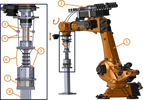
The proximal and distal potted ends of each specimen were affixed to the end effector of the robot, and to a 6-axis robotic control load cell that was mounted to a rigid pedestal, respectively ( and ). To facilitate follower load application, steel cables, which were attached to the linear actuators, passed bilaterally along the spine specimen through cable housings of each vertebral collar and anchored below the specimen to the base of the distal potting cup. The follower load was applied by a pair of linear actuators, which put the steel cables in tension with either 450 N or 900 N of tension in each cable. Meanwhile, the robot’s end effector applied force-controlled compression, defined normal to the superior endplate of L5, to balance the follower load while maintaining anterior-posterior (AP) shear forces at 0 N. Finally, the collar cable housings were adjusted in the AP direction until the application of the compressive follower load at 900 N total resulted in a compression with minimized boundary flexion moment and relative rotations at each intervertebral joint of less than 2 degrees each.
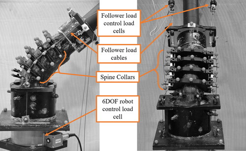
Figure 2. Left lateral (left) and anterior (right) views of an example lumbar spine specimen (sacrum side on the bottom), in the neutral position, mounted in the robotic test fixture, with the follower load cables passing through the spine collars at L1, L2, L3, and L4.
Test methodology
After preparation, each specimen was refrigerated for 16- 40 h until the day of testing. Once the specimen was mounted, a coordinate measurement machine (CMM) [ROMER Absolute Arm, Hexagon AB, Stokholm, Sweden] was used to relate the robot coordinate system to the specimen joint coordinate system (JCS), which was defined using anatomical landmark-based vertebra coordinate systems (Wu et al. Citation2002) on L4 and L5. Specimen anatomical motions were defined as motions of L4 relative to L5, and translations/rotations and forces/moments were measured in the L5 coordinate system. The robotic test system applied force-controlled AP shear force minimization to identify motion paths that applied pure bending loading to the specimen.
To establish the neutral position of each specimen, first, the robot was programmed to find the position and orientation of the end effector (and proximal potting cup) that minimized all forces and moments in the specimen including the compressive force caused by gravity of the superior potting cup. Then, the specimen was flexed or extended until 3Nm flexion or extension resistance. Finally, the neutral position was set at the center of the ±3 Nm motion/laxity region.
For each test, with the spine initially in the neutral position, the follower load (if used) was first applied over a five-second period and held for five seconds to permit equilibration. Then either flexion or extension bending was applied, again over a five-second period, until a pre-determined limit in moment or angle was reached (generally 20–30 degrees from neutral). Individual loading limits were determined based on individual specimens with the goal of completing all testing without damaging the specimen. Generally, each specimen was subjected to flexion, extension, lateral bending, torsion, AP shear, and lateral shear at three different levels of axial compression (0, 900, and 1800 N), but only the response in flexion/extension is reported here (and results from the other loading directions will be reported subsequently). Then the specimen was held at the maximum deformation for five seconds, before the returning to the neutral bending angle (over a five-second period), then holding for five seconds, then removing the follower load over a five second period.
Data processing
While forces and moments were captured and controlled in the JCS, they were transformed and translated to the sacrum coordinate system (Table A2, online supplement) for reporting. Transformation matrices were calculated from CMM measurements made of anatomical landmarks used to define coordinate systems at L5 and the sacrum. Three-dimensional translations and rotations of each of the vertebrae (T12-S1) were calculated from marker motions captured by the stereo-photogrammetric system and related to the individual vertebral coordinate systems (Wu et al. Citation2002) using transformations created by identifying anatomical landmarks (and the markers themselves) from the CT data.
To facilitate identification of the distribution of spinal deformations across the six intervertebral joints (T12-L1 to L5-S1), the peak relative rotation for the pair of vertebrae defining each of the six joints was identified from each test. Then, these maximum relative rotations were normalized by the sum of all six relative rotations in each test, resulting in the percentage of whole-spine deformation occurring at each intervertebral joint for each test.
Response corridor development
Kinetic (moment-angle) and kinematic (L3 vs. L1 and L5 vs. L1 rotations) response corridors were created using methods derived from previously developed techniques (Lessley et al. Citation2004; Shaw et al. Citation2006). While specific details of the methods used here have not been presented in the open literature, identical techniques have been used to create biomechanical response corridors in several studies (Donlon et al. Citation2016; Perez-Rapela et al. Citation2018; Pipkorn et al. Citation2018). In this approach, individual response curves are arc-length parameterized to account for variability in both the loading input and the response. The arc-length parameter of each curve (e.g., flexion moment vs. extension angle) was normalized by the arc-length between two characteristic points on the curve (e.g., the value at time = 0 ms and the value at the maximum flexion moment). Then, the mean and standard deviation of all specimen responses for each test type at each step in the normalized arc-length was calculated. Finally, the upper and lower bounds of each corridor was defined as the set of ellipses, with centers at each step in normalized arc-length along the mean curve, and semi-axes proportional to the standard deviation in each axis at each step in normalized arc-length.
Results
All seven specimens successfully underwent the entire battery of tests without structural or material failure. The seven specimens exhibited generally similar responses, with only specimen M1’s kinematic response differing from the other specimens due to a sacralized L5 vertebra.
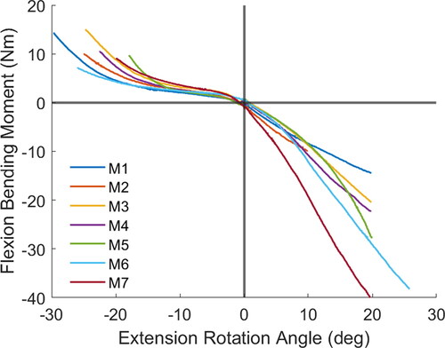
Without axial compressive load, the lumbar spine exhibited a stiffer response in extension than in flexion, but this effect diminished with increasing axial compression ( and Figure A2, online supplement). Further, the lumbar spine exhibited a nonlinear kinetic response in flexion without axial compression, with stiffnesses increasing near the end of the loading regime. However, with axial compression at 900 N or 1800 N, the flexion responses remained relatively linear, albeit stiffer, compared to the case with no axial compression. Extension responses with and without axial compression did not illustrate the nonlinear effect seen in the unloaded flexion response and exhibited mild stiffening with axial compressive load. Overall, variation in individual specimen kinetic responses increased with increasing follower load.
Figure 3. Flexion/extension response of each lumbar spine specimen with no axial compression. Flexion moments and extension angles are shown as positive, whereas extension moments and flexion angles are negative.
The kinematic response data collected in this study () show the lumbar spine does not evenly distribute deformations across the intervertebral levels, and the distribution is specific to loading direction (flexion vs. extension) and to the amount of axial compressive load applied. For instance, in flexion with no axial compression, approximately half of the total bending angle deformation occurs in the L5-S1 joint, and most of the remaining deformation occurs at the L3-L4 and L4-L5 joints, with very little deformation occurring in the proximal joints. Increasing the axial load in flexion resulted in a reduction of deformation at L5-S1, and increases at most other levels, resulting in the L4-L5 joint showing the greatest deformation under 1800 N of axial load. In extension with no axial load, however, deformations were more evenly distributed across the four most distal joints, with the L2-L3 joint exhibiting the greatest deformations. The distribution also shifted with the introduction of axial load, but the greatest deformations were still at the proximal end (L1-L2). Individual kinematic responses of each specimen showed more uniformity across specimens in comparing rotations at L3 relative to L1 (Figures A3 and A5, online supplement) than in rotations at L5 relative to L1 (Figures A4 and A6, online supplement) for both flexion and extension.
Figure 4. Intervertebral joint deformations (flexion/extension angle) as a percentage of whole spine deformation (bending angle) by level and axial compressive load. For instance, the sum of the 0 N bars in flexion is 100%.
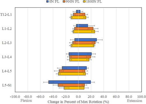
Figure 5. Moment-angle average responses (dashed lines) and upper and lower corridor bounds (solid lines) for each of the three levels of axial compressive load for the lumbar spine in flexion. Flexion moment and angle are shown positive and negative, respectively.
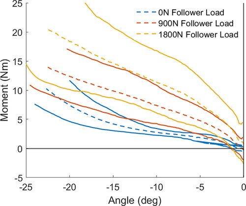
Figure 6. L5 rotation vs. L1 rotation average responses (dashed lines) and upper and lower corridor bounds (solid lines) for each of the three levels of axial compressive load for the lumbar spine in flexion. Flexion angles are shown negative.
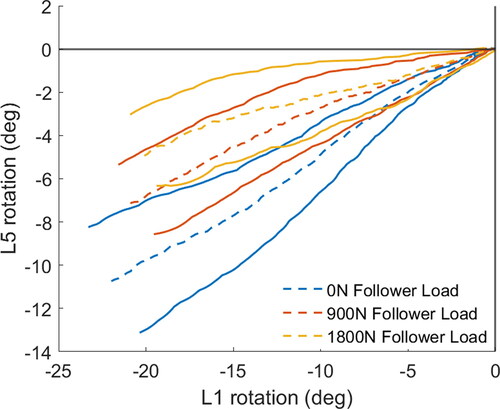
Kinetic (moment vs. angle) and kinematic (L3 vs. L1 and L5 vs. L1) response corridors for extension (Figure A7, online supplement) and flexion (Figure A8, online supplement) more clearly illustrate how specimen responses vary with test conditions. For instance, there is a noticeable difference in lumbar stiffness in flexion with increasing follower load (), and a noticeable reduction in the amount of L5 rotation relative to L1 rotation () with increasing follower load.
Discussion
This study aimed to characterize the biomechanical response of the lumbar spine in flexion and extension and illustrate how that response changes with varying axial loads. The biomechanical responses captured included the load-deformation or kinetic response, measured in bending moment relative to bending angle, and the kinematic response, which describes how the deformation of the spine is distributed across the individual intervertebral motion segments throughout the spine. Traditionally, biomechanical response targets for defined-mechanism loading (e.g., long bone bending) of component segments are provided as kinetic corridors to describe the load-deformation (e.g., applied force vs. beam deflection) (cf. Ivarsson et al. Citation2005). However, whole body response in simulated crash sled experiments is typically characterized using kinematic corridors to illustrate how individual segments move relative to one another (c.f. Richardson et al. Citation2020b). Since the lumbar spine has both individual segments (vertebra) that move relative to one another, and it includes compliant soft-tissues (intervertebral disks and ligaments) that will undergo non-negligible deformations under sub-injurious loads, both the kinetic and kinematic responses were a target of this study. The kinematics data illustrated the deformation under flexion and extension bending was not evenly distributed across the individual intervertebral joints, and the locus of deformation changed depending on loading direction (flexion vs. extension) and level of axial compression. As a result, for instance, flexion of the spine will cause the spine to change its overall shape due to the non-uniform deformation, and such shape changes will affect the trajectory/excursion of the torso and the head of a human surrogate in a crash simulation. Similarly, the total amount of deformation is determined by the magnitude of the applied load, which also controls torso and head kinematics. As a result, differences in the stiffness or the distribution of deformation in the lumbar spine of an ATD or an HBM may affect the accuracy of injury predictions measured with those tools.
This study also aimed to capture the response of the lumbar spine under axial compressive load, which was applied with a follower load mechanism. Unlike most previous uses of a follower load where cable tension is controlled with weights and gravity, this study incorporated computer-driven load control (with linear actuator motors), which provided for a straightforward approach to applying and adjusting the level of axial compression. Further, unlike other previous studies, this study incorporated spinal collars, which allowed for adjustment of the location of each of the follower load cables in the AP-direction relative to the specimen (Figure A1, online supplement). When the follower load was first applied, rotations of one vertebra relative to adjacent vertebrae were noted, which indicated the follower load was not aligned with the center of rotation of the specimen (i.e., application of the follower load caused flexion or extension, and not pure compression, at a two-vertebra motion segment). By starting proximally, and performing iterative adjustment, the position of each follower load cable in each spinal collar was adjusted until bending at each joint was minimized (less than 2 degrees of angle change under 900 N) and the follower load provided pure compression. The study by Patwardhan et al. (Citation1999) discusses the importance of aligning the follower load mechanism to produce compression and not cause bending, but fails to articulate a method for doing so. The solution used here was simply to mount the cable housing on threaded rods to permit fine adjustment of the location. In practice no more than three tests for each joint were required to achieve the desired positions. Since the final position of the cables did not necessarily align with the coordinate system of each vertebra or the axis of moment measurement, the application of axial compression via the follower load mechanism resulted in small initial flexion/extension bending moments. These can be seen in the 900 N and 1800 N case kinetic response curves (Figure A2, online supplement) and this can also be seen in the response corridors (Figures A7 and A8, online supplement) where the moment is non-zero with 0 degrees of deformation. In an ATD, a follower load is not necessary, even in the case of the curved Hybrid III spine, since a follower load is only necessary to mimic the human’s torso musculature that directs the load along the human’s curvature. Both bending and axial compression loads can simply be applied through the ends of ATD spines with any test device capable of multi-directional load control. Although, in an ATD test, bending moments should be applied about a location that is anatomically similar to the T4/T5 joint, which could be identified, as in the PMHS. Similarly, in an HBM, axial compression can be applied perpendicular to the endplates at each level directly to simulate the effect of the follower load used in this study.
While lumbar spine axial compression loading in HBMs and ATDs as high as 5000 N has been predicted in reclined simulations (Gepner et al. Citation2019, Ostling et al. Citation2021), the study by Tushak et al. (Citation2022) suggests that axial compression of approximately 4500 N will carry a 50% risk of vertebral body fracture. Since this study was designed to collect data on each specimen in flexion/extension, but also in shear, torsion, and lateral bending, care was taken to avoid fractures or other damages to the specimens. Considering the injury tolerance of the spine and capability of the hardware, a maximum of 1800 N of axial compression was used, and 900 N was used to assess the linearity of the effect of follower load. Generally, this study showed that the effect of compressive loading was linear: the difference between 900 N and 0 N of follower load was approximately equal to the difference in response for 1800 N and 900 N follower load cases. As a result, future studies may consider only a single axial compression level (beyond 0 N) to reduce the number of tests required. This study also illustrates a methodology that can be used to apply higher loads to the lumbar spine to characterize biomechanical response at loads that approach failure. However, this approach cannot be used to assess the tolerance to injury in this loading mode, since the addition of the spine collars and the follower load mechanism is hypothesized to affect the failure tolerance.
It should be noted that the neutral lumbar position/orientation is not necessarily representative of the lumbar shape for standing or seated occupants. It was simply the position/orientation of each individual specimen that minimized shear forces and moments at the L4-L5 intervertebral joint and was centered in flexion/extension between ±3Nm of bending moment. Considering the response in flexion exhibited nonlinear behavior and a lower stiffness in flexion compared to extension, if the neutral position in flexion/extension was instead centered around ±10 Nm, the neutral position would have been different than used here. Despite this, the same approach can be used to define the neutral position in HBMs and ATDs to facilitate surrogate evaluations with the provided data. Similarly, to facilitate easy direct comparison to HBMs and ATDs, reporting the loads in a coordinate system defined by the sacrum, allowed for the loads to be reported in a coordinate system fixed to the specimen that can easily be defined on other surrogates.
While the loading applied in this study was quasi-static, which was necessary for the force-controlled follower load mechanism to maintain a consistent axial compression throughout the loading, it effectively illustrated the complex bending response sensitivity to axial compression dictated by the human lumbar spine’s anatomy. Further, both this sensitivity to axial load and the sensitivity to loading rate that is characteristic of biological tissues are biomechanical characteristics that may affect injury prediction, and thus if ATDs and HBMs can exhibit such sensitivities, they can be deployed to predict injury over a broad range of loading conditions. The data presented in this study provide a benchmark to assess ATDs and HBMs for the sensitivity to axial compression. Lumbar spine loading rate-sensitivity can be measured in tissue-level experiments (like tensile testing of ligaments or compression testing of intervertebral disks), and introduced into ATDs and HBMs using other methods (like a scaling function to include strain-rate hardening in an HBM material or by tuning the elastomer properties in an ATD). As a result of this rate-sensitivity, failure tolerance of the lumbar spine may be better captured in dynamic impact experiments (Tushak et al. Citation2022), where assessment of axial load sensitivity was not possible because a consistent axial load could not be maintained.
Lastly, the robotic test system permitted the application of multi-axis load-controlled boundary conditions, which do not require geometric scaling (which might be required if displacements rather than loads are test inputs) for application to ATD or HBM spines despite differences in size and shape. As a result, the combination of methods used, and the resulting kinetic and kinematic response corridors provide an ideal set of response benchmarking data that can be used to evaluate ATDs and HBMs in future studies.
Supplemental Material
Download Zip (2.5 MB)Acknowledgements
We would like to acknowledge the personnel of UVA’s Center for Applied Biomechanics who provided technical support for this study.
Additional information
Funding
References
- Adams MA, Dolan P. 1996. Time-dependent changes in the lumbar spine’s resistance to bending. Clin Biomech (Bristol, Avon). 11(4):194–200. doi:10.1016/0268-0033(96)00002-2.
- Adams MA, Dolan P. 2011. Biomechanics of vertebral compression fractures and clinical application. Arch Orthop Trauma Surg. 131(12):1703–1710. doi:10.1007/s00402-011-1355-9.
- Crisco JJ, Panjabi MM, Yamamoto I, Oxland TR. 1992. Euler stability of the human ligamentous lumbar spine. Part II: experiment. Clin Biomech (Bristol, Avon). 7(1):27–32. doi:10.1016/0268-0033(92)90004-N.
- Donlon JP, Joodaki H, Toczyski J, Lessley D, Forman JF. 2016. Biofidelity corridors using arc-length parameterization. In Proceedings of the 44th International Workshop on Human Subjects for Biomechanical Research.
- French HD, Somasundaram AJ, Schaefer NR, Laherty RW. 2014. Lumbosacral transitional vertebrae and its prevalence in the Australian population. Global Spine J. 4(4):229–232. doi:10.1055/s-0034-1387808.
- Fry RW, Alamin TF, Voronov LI, Fielding LC, Ghanayem AJ, Parikh A, Carandang G, Mcintosh BW, Havey RM, Patwardhan AG. 2014. Compressive preload reduces segmental flexion instability after progressive destabilization of the lumbar spine. Spine. 39(2):E74–E81. doi:10.1097/BRS.0000000000000093.
- Gaffey JL, Ghanayem AJ, Voronov ML, Havey RM, Carandang G, Abjornson C, Patwardhan AG. 2010. Effect of increasing implant height on lumbar spine kinematics and foraminal size using the ProDisc–L prosthesis. Spine. 35(19):1777–1782. doi:10.1097/BRS.0b013e3181ebaa4d.
- Gepner BD, Draper D, Mroz K, Richardson R, Ostling M, Pipkorn B, Forman JL, Kerrigan JR. 2019. Comparison of human body models in frontal crashes with reclined seatback. 2019 IRCOBI Conference on the Biomechanics of Injury. IRC-19-44. International Research Council on the Biomechanics of Injury (IRCOBI). www.ircobi.org.
- Gepner BD, Toczyski J, Rawska K, Moreau D, Kerrigan JR. 2020. Sensitivity of human body model response relative to the lumbar spine and pelvic tissue formulation. 2020 IRCOBI Conference on the Biomechanics of Injury. IRC-20-20. International Research Council on the Biomechanics of Injury (IRCOBI). www.ircobi.org.
- Goel VK, Panjabi MM, Patwardhan AG, Dooris AP, Serhan H. 2006. Test protocols for evaluation of spinal implants. JBJS. 88(suppl_2):103–109. doi:10.2106/JBJS.E.01363.
- Ivarsson BJ, Kerrigan, JR, Lessley DJ, Drinkwater DC, Kam CY, Murphy DB, Crandall JR, Kent RW. 2005. Dynamic response corridors of the human thigh and leg in non-midpoint three-point bending. SAE Transactions: Journal of Passenger Cars-Mechanical Systems. 114(6):193–204.
- Koppel S, Octavio J, Bohman K, Logan D, Raphael W, Jimenez Q, Lopez-Valdes F. 2019. Seating configuration and position preferences in fully automated vehicles. Traffic Inj Prev. 20(sup2):S103–S109. doi:10.1080/15389588.2019.1625336.
- Lessley D, Crandall J, Shaw CG, Kent R, Funk J. 2004. A normalization technique for developing corridors from individual subject responses. SAE Technical Paper 2004-01–0288. Warrendale, PA: SAE International. doi:10.4271/2004-01-0288.
- Li Y, Kelly BP, DiAngelo DJ. 2011. Development of a finite element lumbar segment model for simulation of coupled loading conditions validated with in vitro experimental studies. ASME 2011 Summer Bioengineering Conference Parts A and B. American Society of Mechanical Engineers. p. 865–66. doi:10.1115/SBC2011-53972
- Lin HS, Liu YK, Adams KH. 1978. Mechanical response of the lumbar intervertebral joint under physiological (complex) loading. J Bone Joint Surg. 60(1):41–55. doi:10.2106/00004623-197860010-00006
- Mageswaran P, Techy F, Colbrunn RW, Bonner TF, McLain RF. 2012. Hybrid dynamic stabilization: a biomechanical assessment of adjacent and supraadjacent levels of the lumbar spine: laboratory investigation. J. Neurosurg. Spine. 17(3):232–242. doi:10.3171/2012.6.SPINE111054
- Mroz K, Östling M, Richardson R, Kerrigan J, Forman J, Gepner B, Lubbe N, Pipkorn B. 2020. Effect of seat and seat belt characteristics on the lumbar spine and pelvis loading of the SAFER human body model in reclined postures. 2020 IRCOBI Conference on the Biomechanics of Injury. IRC-20-58. International Research Council on the Biomechanics of Injury (IRCOBI). www.ircobi.org.
- Nachemson AL. 1981. Disc pressure measurements. Spine. 6(1):93–97. doi:10.1097/00007632-198101000-00020
- Östling M and Larsson A. 2019. Occupant activities and sitting positions in automated vehicles in China and Sweden. Proceedings of 26th International Conference on the Enhanced of Safety Vehicles (ESV). 19-0083. National Highway Traffic Safety Administration (NHTSA). https://www-nrd.nhtsa.dot.gov/departments/esv/26th/.
- Östling M, Lundgren C, Lubbe N, Huf A, Wernicke P, Pipkorn B. 2021. The influence of a seat track load limiter on lumbar spine compression forces in relaxed, reclined, and upright seating positions: a sled test study using THOR-50M. 2021 IRCOBI Conference on the Biomechanics of Injury. IRC-21-46. International Research Council on the Biomechanics of Injury (IRCOBI). www.ircobi.org.
- Patwardhan AG, Havey RM, Meade KP, Lee B, Dunlap B. 1999. A follower load increases the load-carrying capacity of the lumbar spine in compression. Spine. 24(10):1003–1009. doi:10.1097/00007632-199905150-00014
- Patwardhan AG, Havey RM, Carandang G, Simonds J, Voronov LI, Ghanayem AJ, Meade KP, Gavin TM, Paxinos O. 2003. Effect of compressive follower preload on the flexion–extension response of the human lumbar spine. J Orthop Res. 21(3):540–546. doi:10.1016/S0736-0266(02)00202-4.
- Perez-Rapela D, Markusic C, Whitcomb B, Pipkorn B, Forman JL, Donlon JP, Acosta S, Crandall JR. 2018. Comparison of WorldSID to PMHS kinematics in far-side impact. 2018 IRCOBI Conference on the Biomechanics of Injury. IRC-18-91. International Research Council on the Biomechanics of Injury (IRCOBI). www.ircobi.org.
- Pipkorn B, Larsson K, Perez-Rapela D, Markusic C, Whitcomb B, Ayyagari M, Sunnevang C. 2018. Occupant protection in far-side impacts. 2018 IRCOBI Conference on the Biomechanics of Impacts. IRC-18-16. www.ircobi.org.
- Rawska K, Gepner B, Kulkarni S, Chastain K, Zhu J, Richardson R, Perez-Rapela D, Forman J, Kerrigan JR. 2019. Submarining sensitivity across varied anthropometry in autonomous driving system environment. Traffic Inj Prev. 20(sup2):S123–S127. doi:10.1080/15389588.2019.1655734.
- Rawska K, Gepner B, Moreau D, Kerrigan JR. 2020. Submarining sensitivity across varied seat configurations in autonomous driving system environment. Traffic Inj Prev. 21(sup1):S1–S6. doi:10.1080/15389588.2020.1791324.
- Reed MP, Ebert SM, Jones MLH, Hallman JJ. 2020. Prevalence of non-nominal seat positions and postures among front-seat passengers. Traffic Inj Prev. 21(sup1):S7–S12. doi:10.1080/15389588.2020.1793971.
- Renner SM, Natarajan RN, Patwardhan AG, Havey RM, Voronov LI, Guo BY, Andersson G.B, An HS. 2007. Novel model to analyze the effect of a large compressive follower pre-load on range of motions in a lumbar spine. J. Biomech. 40(6):1326–32. doi:10.1016/j.jbiomech.2006.05.019
- Richardson R, Donlon JP, Jayathirtha M, Forman JL, Shaw G, Gepner B, Kerrigan JR, Ostling M, Mroz K, Pipkorn B. 2020a. Kinematic and injury response of reclined PMHS in frontal impacts. Stapp Car Crash J. 64:83–153. doi:10.4271/2020-22-0004.
- Richardson R, Jayathirtha M, Chastain K, Donlon JP, Forman J, Gepner B, Ostling M, Mroz K, Shaw G, Pipkorn B, et al. 2020b. Thoracolumbar spine kinematics and injuries in frontal impacts with reclined occupants. Traffic Inj Prev. 21(sup1):S66–S71. doi:10.1080/15389588.2020.1837365.
- Rohlmann A, Neller S, Claes L, Bergmann G, Wilke H-J. 2001. Influence of a follower load on intradiscal pressure and intersegmental rotation of the lumbar spine. Spine. 26(24):E557–E561. doi:10.1097/00007632-200112150-00014
- Shaw JM, Herriott RG, McFadden JD, Donnelly BR, Bolte JH. 2006. Oblique and Lateral Impact Response of the PMHS Thorax. Stapp Car Crash J. 50:147–167. doi:10.4271/2006-22-0007.
- Tushak SK, Donlon JP, Gepner BD, Chebbi A, Pipkorn B, Hallman JJ, Forman JL, Kerrigan JR. 2022. Failure tolerance of the human lumbar spine in dynamic combined compression and flexion. J Biomech. 135:111051. doi:10.1016/j.jbiomech.2022.111051.
- Wilke H-J, Rohlmann A, Neller S, Graichen F, Claes L, Bergmann G. 2003. ISSLS prize winner: a novel approach to determine trunk muscle forces during flexion and extension: a comparison of data from an: in vitro: experiment and: In vivo: measurements. Spine. 28(23):2585–93. doi:10.1097/01.BRS.0000096673.16363.C7
- Wu G, Siegler S, Allard P, Kirtley C, Leardini A, Rosenbaum D, Whittle M, D'Lima DD, Cristofolini L, Witte H, et al. 2002. ISB recommendation on definitions of joint coordinate system of various joints for the reporting of human joint motion – part I: ankle, hip and spine. J Biomech. 35(4):543–548. doi:10.1016/s0021-9290(01)00222-6.
- Yang SW, Langrana NA, Lee CK. 1985. Biomecahnics of lumbar spine in biaxial loads. Proceedings of the Eleventh Annual Northeast Conference of Bioengineering. p. 326–329.