
 ?Mathematical formulae have been encoded as MathML and are displayed in this HTML version using MathJax in order to improve their display. Uncheck the box to turn MathJax off. This feature requires Javascript. Click on a formula to zoom.
Abstract
This article investigates nonlinear free vibrations of porous functionally graded (FG) annular spherical shell segments surrounded by elastic medium and reinforced by circumferential stiffeners. Porous FG material contains distributed even and un-even porosities and is modeled based on refined power–law function. The governing equations of stiffened porous annular spherical shell segments have been derived according to thin shell theory with the geometrical nonlinear in von Karman–Donnell sense and the smeared stiffeners method. An analytical trend has been provided for solving the nonlinear governing equations. Obtained results demonstrate the significance of porosity distribution, geometric nonlinearity, foundation factors, stiffeners and curvature radius on vibration characteristics of porous FG annular spherical shell segments.
1. Introduction
Functionally graded materials appropriately incorporate the microstructure and functions and possess preferable mechanical properties compared to usual multi-layered composites leading to their usage in promising fields of materials science (Azimi et al. Citation2017; Mirjavadi et al. Citation2017; Azimi et al. Citation2018; Mirjavadi, Afshari, Barati, et al. Citation2018; Al-Maliki, Faleh, and Alasadi Citation2019; Ebrahimi, Dabbagh, and Rastgoo Citation2019; Mirjavadi, Forsat, Hamouda, et al. Citation2019; Mirzaei Citation2019). Commonly, a functional gradient (FG) material is constructed from metallic and ceramic constituents (Abdelaziz et al. Citation2017; Mahmoudi et al. Citation2019; Wang et al. Citation2019; Wu et al. Citation2019; Trinh and Kim Citation2019a, Citation2019b). Material imperfections in a FG material are obvious during the production period, leading to dispersion of pores within the material texture (Wattanasakulpong et al. Citation2012; Li, Wu, Chen, Cheng, et al. Citation2018; Ahmed, Fenjan, and Faleh Citation2019; Hamad, Khalaf, and Faleh Citation2019; Ahmed et al. Citation2020). Furthermore, the shapes and distributions of porosities are controllable via the production methods. For simulating the influences of the porosities on the mechanical characteristics of an FG material, two kinds of dispersion for porosities may be introduced, namely, even (uniform) dispersion and un-even dispersion, and a refined power–law function can be used for describing the material variation. According to the refined power–law function, many researchers systematically examined the stability and vibrations of porous FG structural components at different scales (Wu et al. Citation2018; Addou et al. Citation2019; Liu et al. Citation2019; Trinh, Nguyen, and Kim Citation2019). These investigations have reported that porosities play a remarkable role in analyzing the mechanical behaviors of beam and plate structures. Although there were many articles on the mechanical behaviors of porous FG structures, no one study the nonlinear vibration behavior of porous FG annular spherical shell segments.
The annular spherical shell is broadly applied in several engineering fields including civil, mechanical, aerospace engineering. The annular spherical shell and annular spherical segment are two particular shapes of the spherical shell. Due to significant practical application of such structures, some researchers studied their mechanical behaviors via different approaches. For example, Duc, Quang, and Anh (Citation2017) studied vibrational behavior of FG spherical shells rested on elastic substrate. Effects of elastic boundary conditions on free vibration behavior of thin spherical shells have been examined by Xie, Chen, and Li (Citation2017). Based on an analytical solution, Duc et al. (Citation2019) examined nonlinear dynamic behaviors of annular spherical shells made of nano-composite materials. Also, Li, Wu, et al. (Citation2019) provided a semi-analytical approach for examining linear vibration behavior of annular spherical shells under different edge conditions. Recently, Gao et al. (Citation2020) examined free vibrations of functionally graded spherical shell based on Ritz solution.
Recently, several researchers have focused on the static and dynamical characteristics of eccentrically stiffened plates and shells since such structural components are usually fortified with employment of stiffening elements to introduce the benefits of improved load-carrying capabilities with relatively low extra weight penalties. Furthermore, eccentrically stiffened plates and shells are main structures in engineering scheme of missile, aircraft and aerospace industries (Ninh and Bich Citation2016; Su et al. Citation2019). Despite the evident significance in practical applications, it is realized from the literature that studies on vibrations of annular spherical segment made porous FG material and reinforced by arrays of stiffeners are comparatively scarce.
Within this article, an investigation of nonlinear vibration behaviors of stiffened annular spherical shell segments constructed from porous FG materials has been presented. Porous FG material contains distributed even and un-even porosities and is modeled based on refined power–law function. The governing equations of stiffened porous annular spherical shell segments have been derived according to thin shell theory with the geometrical nonlinear in von Karman–Donnell sense and the smeared stiffeners method. Based on smeared stiffeners method, the force and moment resultants can be established as functions of stiffeners geometries and spacing (Hao et al. Citation2014). An analytical trend has been provided for solving the nonlinear governing equations. Obtained results demonstrate the significance of porosity distribution, geometric nonlinearity, foundation factors, stiffeners and curvature radius on vibration characteristics of porous FG annular spherical shell segments.
2. Material properties for porous FG annular spherical shell
Pores within the material texture may affect both elastic modulus and mass density of FGMs. Based upon refined power–law function, one can introduce the elastic modulus (E) and mass density () of FG materials as functions of porosity volume fraction (ξ) and gradient exponent (p) as (Ahmed, Fenjan, and Faleh Citation2019):
Even porosity distribution:
(1)
(1)
(2)
(2)
Un-even porosity distribution:
(3)
(3)
(4)
(4)
In above relations, subscripts c and m respectively denote the material properties of ceramic and metallic ingredients.
3. Formulation for annular spherical shell segment
A porous FG annular spherical shell segment of thickness h has been depicted in which contains radial and circumferential stiffeners as shown in . Here, r is radius of the spherical shell defined as a function of base radius (R) as:
(5)
(5)
where
is the meridional angle of the spherical shell. Also, considering the shallowness of the spherical shell it must be stated that
Based on this shell assumption, the strain field may be defined in below form (Barati and Zenkour Citation2019):
(6)
(6)
in which
(7)
(7)
Figure 1. Configuration of annular spherical shells.
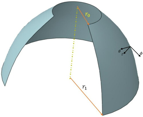
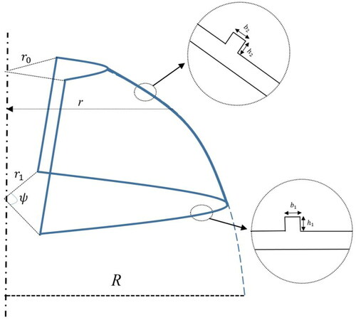
Figure 2. Geometry of the shell with stiffeners.
Above field contains (u, v, w) displacements in (θ, z) directions. By using the classic shell assumption and FG material, stress–strain relations can be summarized as (Ahmed, Fenjan, and Faleh Citation2019):
(8)
(8)
where σi (i = r, θ, r θ) are stress field components. The stresses leads to below resultants via integrating EquationEq. (8)
(8)
(8) over shell thickness as:
(9)
(9)
(10)
(10)
(11)
(11)
(12)
(12)
(13)
(13)
(14)
(14)
in which Es is Young’s modulus of stiffeners; s1 nd s2 are spacing of stiffeners; As1 and As2 are cross sections of stiffeners and
(15)
(15)
Detailed expressions of (Aij, Bij, Dij) based on even porosity distribution have been presented in Appendix and
(16)
(16)
Note that h1 and h2 are height of stiffeners; b1 and b2 are width of stiffeners. Also, nr and nθ are the number of stiffeners. Now, one can express the governing equations for an annular spherical shell surrounded by elastic medium (Li, Wu, et al. Citation2019) with parameters kw, kp as (Duc et al. Citation2017):
(17)
(17)
(18)
(18)
(19)
(19)
where
By substituting EquationEqs. (9)–(14) into EquationEqs. (17)
(17)
(17) and Equation(19)
(19)
(19) , nonlinear governing equations in terms of displacement components are expressed as follows:
(20)
(20)
(21)
(21)
(22)
(22)
4. Solution procedure
Here, the solution of nonlinear vibration problem of porous FG annular spherical shell has been provided. First, it must be stated that the edges of annular spherical shell are simply-supported based on below conditions:
(23)
(23)
where r0 is the inner radius and
is the open angle of annular spherical shell. In general form, the displacements of annular spherical shell may be assumed as:
(24)
(24)
(25)
(25)
(26)
(26)
where (
) are the displacements amplitudes and the functions
and
are the test functions which are selected as (Duc, Quang, and Anh Citation2017):
(27)
(27)
Introducing each governing equation as Pi (u, v, w)=0 with (i = 1,2,3) and placing displacement assumptions presented as EquationEqs. (24)–(26) into Pi results in below equations based on Galerkin’s method (Fenjan et al. Citation2019; Khalaf, Fenjan, and Faleh Citation2019; Kunbar et al. Citation2019; Al-Maliki et al. Citation2020; Abdulrazzaq et al. Citation2020a; Citation2020b; Fenjan, Hamad, and Faleh Citation2020):
(28)
(28)
(29)
(29)
(30)
(30)
Solving above integrals results in below equations in a simplified form neglecting in-plane inertias:
(31)
(31)
(32)
(32)
(33)
(33)
in which Kij are stiffness matrix components; M is mass matrix and Gi are nonlinear stiffness matrices. Based on EquationEqs. (31)–(32) one can obtain U and V as functions of W and W2 (Muhammad et al. Citation2019):
(34)
(34)
Therefore, EquationEq. (33)
(33)
(33) , with the aid of EquationEq. (34)
(34)
(34) can be reduced to below equation:
(35)
(35)
for which
(36)
(36)
The solving of EquationEq.(35)(35)
(35) can be done based on below approximation (Mirjavadi, Forsat, Hamouda, et al. Citation2019):
(37)
(37)
So that is vibration frequency and
is vibration amplitude. The frequency has been calculated based on the procedure provided by Mirjavadi, Forsat, Hamouda, et al. (Citation2019). Also, some normalized parameters can be introduced in this article such as:
(38)
(38)
5. Results and discussions
In this study, the thickness of annular spherical shell has be assumed as h = 0.03 m. Porous FG material has two constituents which their properties are provided in . However, for simplicity the Poisson ratio is considered as constant v = 0.3. Based on above information, this section presents obtained results for nonlinear vibration frequencies of porous FG annular spherical shell surrounded by elastic medium. Porosity volume, open angle and stiffeners have great influence on nonlinear vibration behavior of annular spherical shells. In the following paragraphs, the frequency of spherical shell is validated first and then new findings from the present study have been provided and discussed. For all figures, the geometrical parameters of stiffeners are considered to be h1 = 0.5 h, b1 = 0.5 h.
Table 1. Material properties of FGM constituents.
presents frequency validation of spherical shells made of FG material with those of Duc, Quang, and Anh (Citation2017). For the validation, various values of material gradient exponent (p = 0, 1, 5) have been considered. Also, it is considered that R/h = 100. Obtained frequencies are the same as Duc, Quang, and Anh (Citation2017) which highlights the correctness of presented methodology. Also, presents frequency validation of FG spherical shells with the article of Fadaee, Atashipour, and Hosseini-Hashemi (Citation2013) based on different values of curvature radius (R/a) at a fixed material exponent p = 1.
Table 2. Validation of vibration frequency of spherical shell for various material gradient exponent (R/r0=3).
Table 3. Validation of vibration frequency (Hz) of FG spherical shells at curvature radius (p = 1).
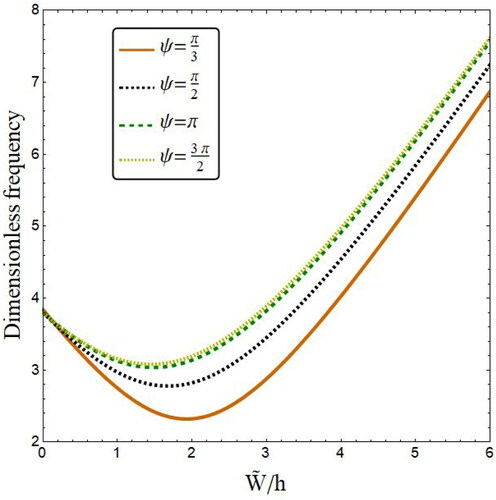
Effect of open angle () on the variation of nonlinear vibration frequency of FG annular spherical shell segment with respect to normalized amplitude (
) has been plotted in . The material gradient index is selected as p = 1 and shell radii are assumed to be r1=100 h and r0=0.5r1. Note that the vibration frequency ignoring geometric nonlinearity can be obtained based on
This figure shows that nonlinear vibration behaviors of annular spherical shell segment rely on the value of open angle. Actually, as the value of open angle increases the nonlinear vibration frequency becomes larger.
Figure 3. Variation of vibration frequency versus normalized deflection of annular spherical shells for various open angles (R = 200 h, r1=100 h, r0=0.5r1, p = 1, ξ = 0.2, Kw=0, Kp=0).
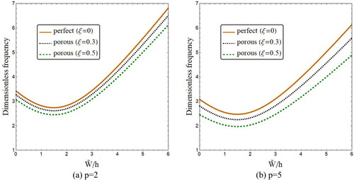
Influences of porosity volume fraction (ξ) on the variation of nonlinear vibration frequency of FG annular spherical shell segment with respect to normalized amplitude have been plotted in when the material gradient exponent is set to p = 2, 5. The distribution type of porosities is considered as even. Also, the shell segment has an open angle of This figure indicates the reduction of vibration frequency with the increase of porosity volume at a, prescribed value of normalized amplitude. Such finding is related to decrease of shell structural stiffness according to the growth of porosities amount. Another important finding is that an increase of FG material exponent results in lower vibration frequencies for annular spherical shell segment.
Figure 4. Variation of vibration frequency versus normalized deflection of annular spherical shells for various porosity volume fractions (R = 200 h, r1=100 h, r0=0.5r1, Kw=0, Kp=0). (a) p = 2; (b) p = 5.
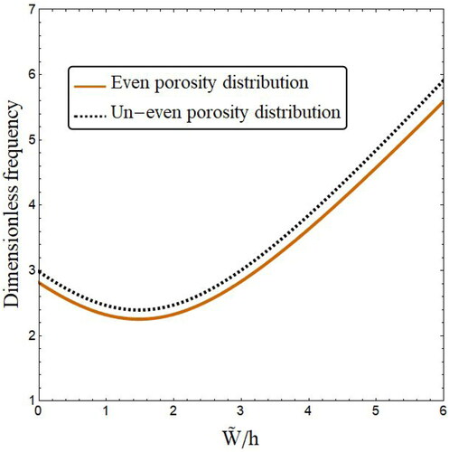
explores the influences of porosities distribution types on nonlinear vibration behavior of FG annular spherical shell at fixed values for material exponent p = 5 and porosities volume ξ = 0.3. One can observe that vibration frequencies based on even type of distribution are smaller than frequencies based on un-even type of distribution. This finding is owning to the fact that porosity based on even type of distribution have been dispersed all over the thickness of annular spherical shell leading to smaller shell stiffness.
Figure 5. Variation of vibration frequency versus normalized deflection of annular spherical shells for various porosity distribution types (R = 200 h, r1=100 h, r0=0.5r1, p = 5, ξ = 0.3, ψ = π).
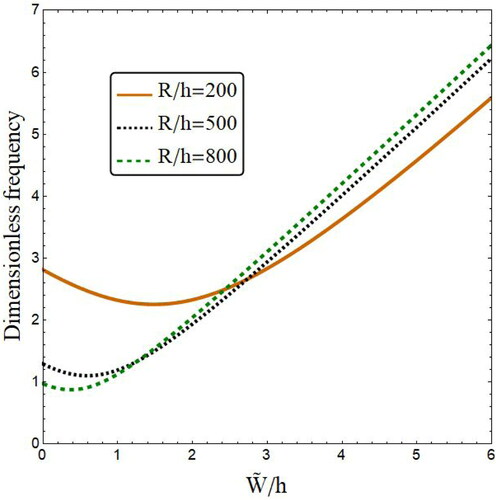
indicates the effect of normalized base radius (R/h) of annular spherical shell on the variation of vibration frequencies with respect to normalized amplitude. Results are presented at fixed values for material exponent p = 5 and porosities volume ξ = 0.3. Also, radii of lower and upper bases are selected as r1=100 h, r0=0.5 r1 and the shell segment has an open angle of As can be seen, the variation of vibration frequency with respect to vibration amplitude has higher rates as the values of R/h is greater. So, effect of R/h on vibration behavior of annular spherical shell segment depends on the value of normalized vibration amplitude.
Figure 6. Variation of vibration frequency versus normalized deflection of annular spherical shells for various porosity distribution types (r1=100 h, r0=0.5r1, p = 5, ξ = 0.3, ψ = π).
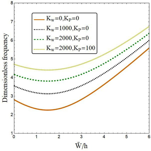
In , influences of foundation parameters (Kw, KP) on the variation of nonlinear vibration frequency of FG annular spherical shell segment with respect to normalized amplitude have been plotted. This figure has been provided based on the assumption of even porosity distribution and ξ = 0.3. As can be seen, an increase of the two foundation parameters results in higher frequency–amplitude curves. However, higher values for Winkler parameter (Kw) than Pasternak parameter (Kp) are needed to affect the vibration frequency of annular spherical shells. This is due to the reason that Kw is corresponding to infinite number of springs leading to discontinuous interaction with spherical shell.
Figure 7. Variation of vibration frequency versus normalized deflection of annular spherical shells for various foundation factors (r1=100 h, r0=0.5r1, p = 5, ξ = 0.3, ψ = π).
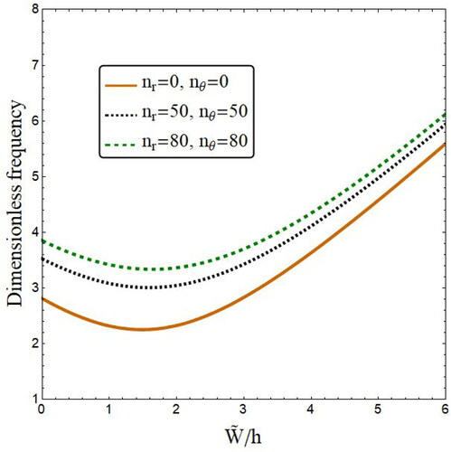
illustrates the effect of stiffener numbers (nr, nθ) of annular spherical shell on the variation of vibration frequencies with respect to normalized amplitude. Results are presented at fixed values for material exponent p = 5 and porosities volume ξ = 0.3. Also, radii of lower and upper bases are selected as r1=100 h, r0=0.5 r1 and the shell segment has an open angle of The geometric parameters of stiffeners are h1=0.5 h and b1=0.5 h. The present figure indicates that stiffened annular spherical shell has enhanced dynamic character since it is reinforced by a system of stiffeners. Therefore, vibration frequencies of stiffened annular spherical shells are higher than those without stiffeners. This issue is much important due to the fact that porous shells have lower vibration frequencies than perfect one. Hence, their vibration properties should be enhanced by adding some stiffeners.
Figure 8. Variation of vibration frequency versus normalized deflection of annular spherical shells for various number of stiffeners (r1=100 h, r0=0.5r1, p = 5, ξ = 0.3, h1=0.5 h, b1=0.5 h, ψ = π).
6. Conclusions
In this research, nonlinear vibration frequencies of annular spherical shell segments made of porous FG materials were examined. Effects of two types of porosity distributions were considered. Also, influences of stiffeners and surrounding medium were included. An analytical trend was proposed to solve the nonlinear governing equations of annular spherical shell. Obtained findings are summarized as follows:
As the value of open angle increases the nonlinear vibration frequency becomes larger.
Another finding is the reduction of vibration frequency with the increase of porosity volume at a prescribed value of normalized amplitude.
Vibration frequencies based on even type of distribution are smaller than frequencies based on un-even type of distribution.
An increase of the two foundation parameters results in higher frequency–amplitude curves.
Vibration frequencies of stiffened annular spherical shells are higher than those without stiffeners.
Acknowledgments
The first and second authors would like to thank FPQ (Fidar project Qaem) for providing the fruitful and useful help.
References
- Abdelaziz, H. H., M. A. A. Meziane, A. A. Bousahla, A. Tounsi, S. R. Mahmoud, and A. S. Alwabli. 2017. An efficient hyperbolic shear deformation theory for bending, buckling and free vibration of FGM sandwich plates with various boundary conditions. Steel and Composite Structures 25 (6):693–704. doi:https://doi.org/10.12989/scs.2017.25.6.693.
- Abdulrazzaq, M. A., R. M. Fenjan, R. A. Ahmed, and N. M. Faleh. 2020a. Thermal buckling of nonlocal clamped exponentially graded plate according to a secant function based refined theory. Steel and Composite Structures 35 (1):147–57.
- Abdulrazzaq, M. A., Z. D. Kadhim, N. M. Faleh, and N. M. Moustafa. 2020b. A numerical method for dynamic characteristics of nonlocal porous metal–ceramic plates under periodic dynamic loads. Structural Monitoring and Maintenance 7 (1):27–42.
- Addou, F. Y., M. Meradjah, A. A. Bousahla, A. Benachour, F. Bourada, A. Tounsi, and S. R. Mahmoud. 2019. Influences of porosity on dynamic response of FG plates resting on Winkler/Pasternak/Kerr foundation using quasi 3D HSDT. Computers and Concrete 24 (4):347–67. doi:https://doi.org/10.12989/cac.2019.24.4.347.
- Ahmed, R. A., R. M. Fenjan, and N. M. Faleh. 2019. Analyzing post-buckling behavior of continuously graded FG nanobeams with geometrical imperfections. Geomechanics and Engineering 17 (2):175–80. doi:https://doi.org/10.12989/gae.2019.17.2.175.
- Ahmed, R. A., R. M. Fenjan, L. B. Hamad, and N. M. Faleh. 2020. A review of effects of partial dynamic loading on dynamic response of nonlocal functionally graded material beams. Advances in Materials Research 9 (1):33–48.
- Al-Maliki, A. F., N. M. Faleh, and A. A. Alasadi. 2019. Finite element formulation and vibration of nonlocal refined metal foam beams with symmetric and non-symmetric porosities. Structural Monitoring and Maintenance 6 (2):147–59. doi:https://doi.org/10.12989/smm.2019.6.2.147.
- Al-Maliki, A. F., R. A. Ahmed, N. M. Moustafa, and N. M. Faleh. 2020. Finite element based modeling and thermal dynamic analysis of functionally graded graphene reinforced beams. Advances in Computational Design 5 (2):177–93.
- Azimi, M., S. S. Mirjavadi, N. Shafiei, and A. M. S. Hamouda. 2017. Thermo-mechanical vibration of rotating axially functionally graded nonlocal Timoshenko beam. Applied Physics A 123 (1):104. doi:https://doi.org/10.1007/s00339-016-0712-5.
- Azimi, M., S. S. Mirjavadi, N. Shafiei, A. M. S. Hamouda, and E. Davari. 2018. Vibration of rotating functionally graded Timoshenko nano-beams with nonlinear thermal distribution. Mechanics of Advanced Materials and Structures 25 (6):467–80. doi:https://doi.org/10.1080/15376494.2017.1285455.
- Barati, M. R., and A. M. Zenkour. 2019. Vibration analysis of functionally graded graphene platelet reinforced cylindrical shells with different porosity distributions. Mechanics of Advanced Materials and Structures 26 (18):1580–8. doi:https://doi.org/10.1080/15376494.2018.1444235.
- Duc, N. D., V. D. Quang, and V. T. T. Anh. 2017. The nonlinear dynamic and vibration of the S-FGM shallow spherical shells resting on an elastic foundations including temperature effects. International Journal of Mechanical Sciences 123:54–63. doi:https://doi.org/10.1016/j.ijmecsci.2017.01.043.
- Duc, N. D., V. T. T. Anh, V. T. Huong, V. D. Quang, and P. D. Nguyen. 2019. Nonlinear dynamic response of nano-composite sandwich annular spherical shells. VNU Journal of Science: Mathematics: Physics 35 (3). doi:https://doi.org/10.25073/2588-1124/vnumap.4360.
- Ebrahimi, F., A. Dabbagh, and A. Rastgoo. 2019. Free vibration analysis of multi-scale hybrid nanocomposite plates with agglomerated nanoparticles. Mechanics Based Design of Structures and Machines 1–24. doi:https://doi.org/10.1080/15397734.2019.1692665.
- Fadaee, M., S. R. Atashipour, and S. Hosseini-Hashemi. 2013. Free vibration analysis of Lévy-type functionally graded spherical shell panel using a new exact closed-form solution. International Journal of Mechanical Sciences 77:227–38. doi:https://doi.org/10.1016/j.ijmecsci.2013.10.008.
- Fenjan, R. M., R. A. Ahmed, A. A. Alasadi, and N. M. Faleh. 2019. Nonlocal strain gradient thermal vibration analysis of double-coupled metal foam plate system with uniform and non-uniform porosities. Coupled Systems Mechanics 8 (3):247–57. doi:https://doi.org/10.12989/csm.2019.8.3.247.
- Fenjan, R. M., L. B. Hamad, and N. M. Faleh. 2020. Mechanical-hygro-thermal vibrations of functionally graded porous plates with nonlocal and strain gradient effects. Advances in Aircraft and Spacecraft Science 7 (2):169–86.
- Gao, C., F. Pang, H. Li, and L. Li. 2020. An approximate solution for vibrations of uniform and stepped functionally graded spherical cap based on Ritz method. Composite Structures 233:111640. doi:https://doi.org/10.1016/j.compstruct.2019.111640.
- Hamad, L. B., B. S. Khalaf, and N. M. Faleh. 2019. Analysis of static and dynamic characteristics of strain gradient shell structures made of porous nano-crystalline materials. Advances in Materials Research 8 (3):179–96.
- Hao, P., B. Wang, G. Li, Z. Meng, K. Tian, and X. Tang. 2014. Hybrid optimization of hierarchical stiffened shells based on smeared stiffener method and finite element method. Thin-Walled Structures 82:46–54. doi:https://doi.org/10.1016/j.tws.2014.04.004.
- Khalaf, B. S., R. M. Fenjan, and N. M. Faleh. 2019. Analyzing nonlinear mechanical–thermal buckling of imperfect micro-scale beam made of graded graphene reinforced composites. Advances in Materials Research 8 (3):219.
- Kunbar, L. A. H., B. M. Alkadhimi, H. S. Radhi, and N. M. Faleh. 2019. Flexoelectric effects on dynamic response characteristics of nonlocal piezoelectric material beam. Advances in Materials Research 8 (4):259–74.
- Li, K., D. Wu, X. Chen, J. Cheng, Z. Liu, W. Gao, and M. Liu. 2018. Isogeometric analysis of functionally graded porous plates reinforced by graphene platelets. Composite Structures 204:114–30. doi:https://doi.org/10.1016/j.compstruct.2018.07.059.
- Li, Q., D. Wu, X. Chen, L. Liu, Y. Yu, and W. Gao. 2018. Nonlinear vibration and dynamic buckling analyses of sandwich functionally graded porous plate with graphene platelet reinforcement resting on Winkler–Pasternak elastic foundation. International Journal of Mechanical Sciences 148:596–610. doi:https://doi.org/10.1016/j.ijmecsci.2018.09.020.
- Li, Q., D. Wu, W. Gao, F. Tin-Loi, Z. Liu, and J. Cheng. 2019. Static bending and free vibration of organic solar cell resting on Winkler–Pasternak elastic foundation through the modified strain gradient theory. European Journal of Mechanics: A/Solids 78:103852. doi:https://doi.org/10.1016/j.euromechsol.2019.103852.
- Li, H., F. Pang, and H. Chen. 2019. A semi-analytical approach to analyze vibration characteristics of uniform and stepped annular-spherical shells with general boundary conditions. European Journal of Mechanics: A/Solids 74:48–65. doi:https://doi.org/10.1016/j.euromechsol.2018.10.017.
- Liu, Z., C. Yang, W. Gao, D. Wu, and G. Li. 2019. Nonlinear behaviour and stability of functionally graded porous arches with graphene platelets reinforcements. International Journal of Engineering Science 137:37–56. doi:https://doi.org/10.1016/j.ijengsci.2018.12.003.
- Mahmoudi, A., S. Benyoucef, A. Tounsi, A. Benachour, E. A. Adda Bedia, and S. R. Mahmoud. 2019. A refined quasi-3D shear deformation theory for thermo-mechanical behavior of functionally graded sandwich plates on elastic foundations. Journal of Sandwich Structures and Materials 21 (6):1906–29. doi:https://doi.org/10.1177/1099636217727577.
- Mirjavadi, S. S., S. Rabby, N. Shafiei, B. M. Afshari, and M. Kazemi. 2017. On size-dependent free vibration and thermal buckling of axially functionally graded nanobeams in thermal environment. Applied Physics A 123 (5):315. doi:https://doi.org/10.1007/s00339-017-0918-1.
- Mirjavadi, S. S., B. M. Afshari, M. R. Barati, and A. M. S. Hamouda. 2018. Strain gradient based dynamic response analysis of heterogeneous cylindrical microshells with porosities under a moving load. Materials Research Express 6 (3):035029. doi:https://doi.org/10.1088/2053-1591/aaf5a2.
- Mirjavadi, S. S., B. M. Afshari, M. Khezel, N. Shafiei, S. Rabby, and M. Kordnejad. 2018. Nonlinear vibration and buckling of functionally graded porous nanoscaled beams. Journal of the Brazilian Society of Mechanical Sciences and Engineering 40 (7):352. doi:https://doi.org/10.1007/s40430-018-1272-8.
- Mirjavadi, S. S., M. Forsat, A. M. S. Hamouda, and M. R. Barati. 2019. Dynamic response of functionally graded graphene nanoplatelet reinforced shells with porosity distributions under transverse dynamic loads. Materials Research Express 6 (7):075045. doi:https://doi.org/10.1088/2053-1591/ab1552.
- Mirjavadi, S. S., B. M. Afshari, M. R. Barati, and A. M. S. Hamouda. 2019. Transient response of porous FG nanoplates subjected to various pulse loads based on nonlocal stress–strain gradient theory. European Journal of Mechanics: A/Solids 74:210–20. doi:https://doi.org/10.1016/j.euromechsol.2018.11.004.
- Mirjavadi, S. S., B. M. Afshari, M. R. Barati, and A. M. S. Hamouda. 2019. Nonlinear free and forced vibrations of graphene nanoplatelet reinforced microbeams with geometrical imperfection. Microsystem Technologies 25 (8):3137–50. doi:https://doi.org/10.1007/s00542-018-4277-4.
- Mirjavadi, S. S., M. Forsat, M. R. Barati, G. M. Abdella, A. M. S. Hamouda, B. M. Afshari, and S. Rabby. 2019. Post-buckling analysis of piezo-magnetic nanobeams with geometrical imperfection and different piezoelectric contents. Microsystem Technologies 25 (9):3477–88. doi:https://doi.org/10.1007/s00542-018-4241-3.
- Mirzaei, M. 2019. Vibrations of FG-CNT reinforced composite cylindrical panels with cutout. Mechanics Based Design of Structures and Machines 1–21. https://doi.org/10.1080/15397734.2019.1705165.
- Muhammad, A. K., L. B. Hamad, R. M. Fenjan, and N. M. Faleh. 2019. Analyzing large-amplitude vibration of nonlocal beams made of different piezo-electric materials in thermal environment. Advances in Materials Research 8 (3):237–57.
- Ninh, D. G., and D. H. Bich. 2016. Nonlinear thermal vibration of eccentrically stiffened ceramic–FGM–metal layer toroidal shell segments surrounded by elastic foundation. Thin-Walled Structures 104:198–210. doi:https://doi.org/10.1016/j.tws.2016.03.018.
- Su, Z., L. Wang, K. Sun, and D. Wang. 2019. Vibration characteristic and flutter analysis of elastically restrained stiffened functionally graded plates in thermal environment. International Journal of Mechanical Sciences 157–158:872–84. doi:https://doi.org/10.1016/j.ijmecsci.2019.05.028.
- Trinh, M. C., and S. E. Kim. 2019a. Nonlinear stability of moderately thick functionally graded sandwich shells with double curvature in thermal environment. Aerospace Science and Technology 84:672–85. doi:https://doi.org/10.1016/j.ast.2018.09.018.
- Trinh, M. C., and S. E. Kim. 2019b. A three variable refined shear deformation theory for porous functionally graded doubly curved shell analysis. Aerospace Science and Technology 94:105356. doi:https://doi.org/10.1016/j.ast.2019.105356.
- Trinh, M. C., D. D. Nguyen, and S. E. Kim. 2019. Effects of porosity and thermomechanical loading on free vibration and nonlinear dynamic response of functionally graded sandwich shells with double curvature. Aerospace Science and Technology 87:119–32. doi:https://doi.org/10.1016/j.ast.2019.02.010.
- Wang, Q., D. Wu, F. Tin-Loi, and W. Gao. 2019. Machine learning aided stochastic structural free vibration analysis for functionally graded bar-type structures. Thin-Walled Structures 144:106315. doi:https://doi.org/10.1016/j.tws.2019.106315.
- Wattanasakulpong, N., B. G. Prusty, D. W. Kelly, and M. Hoffman. 2012. Free vibration analysis of layered functionally graded beams with experimental validation. Materials & Design (1980–2015) 36:182–90. doi:https://doi.org/10.1016/j.matdes.2011.10.049.
- Wu, D., A. Liu, Y. Huang, Y. Huang, Y. Pi, and W. Gao. 2018. Dynamic analysis of functionally graded porous structures through finite element analysis. Engineering Structures 165:287–301. doi:https://doi.org/10.1016/j.engstruct.2018.03.023.
- Wu, D., Q. Wang, A. Liu, Y. Yu, Z. Zhang, and W. Gao. 2019. Robust free vibration analysis of functionally graded structures with interval uncertainties. Composites Part B: Engineering 159:132–45. doi:https://doi.org/10.1016/j.compositesb.2018.09.082.
- Xie, K., M. Chen, and Z. Li. 2017. A semi-analytical method for vibration analysis of thin spherical shells with elastic boundary conditions. Journal of Vibroengineering 19 (4):2312–30. doi:https://doi.org/10.21595/jve.2016.17154.
Appendix 1
where is Gamma function.