
 ?Mathematical formulae have been encoded as MathML and are displayed in this HTML version using MathJax in order to improve their display. Uncheck the box to turn MathJax off. This feature requires Javascript. Click on a formula to zoom.
Abstract
In this work, optimal combinations of macro-layouts and local gradings of triply periodic minimal surface (TPMS)-based lattice structures are obtained by using multi-scale topology optimization. A new innovative framework is proposed by using two density variables in each finite element. The first variable is the local relative lattice density and it sets the effective orthotropic elastic properties of the element, which in turn are obtained by using numerical homogenization of representative volume elements of the particular TPMS-based lattice structure of interest. The second variable is a standard topology optimization macro density variable, which defines if the element should be treated as a void or contain the graded lattice structure by letting this variable be governed by the rational approximation of material properties (RAMP) model. By using such density variables for all elements, the compliance is minimized by separately constraining the volume of lattice structure and the volume of macro-layout by using two independent constraints. For benchmarks in 3 D, it is demonstrated that the stiffness is increased significantly by including local grading of the lattice structure compared to using a constant lattice density. It is also demonstrated how ultra-lightweight designs can be generated using the multi-scale formulation, and how the optimal multi-scale solutions easily can be realized to printable stl-files by using implicit based geometry modeling. Finally, the new multi-scale topology optimization framework is utilized to generate an optimal design combination of macro-layout and local grading of frame-based Gyroid structure for the established GE-bracket benchmark.
1. Introduction
The use of lattice structures in design for additive manufacturing has quickly emerged as a popular and efficient design alternative for creating innovative multifunctional lightweight solutions (Seharing, Azman, and Abdullah Citation2020; Plocher and Panesar Citation2018). In particular, the family of triply periodic minimal surfaces (TPMS) studied in detail by Schoen (Citation1970) for generating lattice structures seems extra promising. The Gyroid surface is probably the most well-known of Schoen’s 12 TPMS-based surfaces, but others exist such as e.g., the G-prime and the Schwarz-D surface. An extensive study of the mechanical properties of several TPMS-based lattices can be found in the work by Maskery et al. (Citation2018). Typically, in the design process, bulk parts are replaced by these kind of lattice structures, which then are globally graded with finite element analysis in a trial-and-error manner in order to satisfy design requirements and additive manufacturing constraints.
A better mechanical design approach would be to simultaneously replace the bulk part with a new optimal macro-layout containing locally optimal graded lattice structures. In this paper, such an approach is presented by proposing a new multi-scale topology optimization framework for simultaneously generating optimal combinations of macro-layouts and local gradings of periodic lattice structures. Additive manufacturing constraints on the thickness of the lattices are also included in the formulation by constraining the relative density of the lattice with lower and upper limits. Recently, Jansen and Pierard (Citation2020) presented similar ideas using a hybrid approach in order to simultaneously optimize the shape of the macroscale structure and the functionally graded lattices inside this design domain. Their approach was demonstrated by studying the well-known GE bracket. This benchmark was recently studied by Strömberg (Citation2021a) by grading shell-based TPMS lattice structures using a single variable approach. The macro-layout in that work was obtained by forcing low densities below a prescribed limit toward zeros using a Sigmoid filter. In this work, the macro layout is obtained as one part of the optimal solution using a standard macro topology optimization density variable governed by RAMP (Stolpe and Svanberg Citation2001), which in turn is filled with graded lattice structure given as a second part of the optimal solution using an additional local lattice density variable governed by effective elastic properties of the lattice.
A review on current and future trends in topology optimization, covering grading of lattices using topology optimization, can be found in (Liu et al. Citation2018). Strategies for functionally graded lattice structures by using topology optimization were discussed by Panesar et al. (Citation2018). A recent review on design, optimization and additive manufacturing of cellular structures was given by Nazir et al. (Citation2019), considering both strut- and TPMS-based lattices structures. A most recent review on multi-scale topology optimization is presented by Wu, Sigmund, and Groen (Citation2021). Most of the work on optimal grading of lattices structures using topology optimization is for strut-based lattices or on honeycomb lattices in 2 D. A mathematical rigourous work on topology optimization of periodic microstructures by the homogenization method is presented by Allaire, Geoffroy-Donders, and Pantz (Citation2019). An early work on grading honeycomb lattices in 2 D without macro-layout was suggested and validated by Zhang et al. (Citation2015). This work was extended in (Zhang, Liu, and To Citation2017) to include anisotropic elasticity. Anisotropic optimization of lattice structures was recently considered by Li et al. (Citation2020). Daynes et al. (Citation2017) graded struts by minimizing compliance and utilized the principle stress directions to define the layouts of the struts. Jin, Li, and Zhang (Citation2018) performed sizing of struts by mapping topology optimization results onto strut-based lattices. A two-step sequential level-set approach for macro-layout and grading of struts in 2 D was presented in Wang et al. (Citation2018a). Natural frequency optimization of strut lattices was performed in Cheng et al. (Citation2018a) and of honeycomb structures in Wang et al. (Citation2018b). Maximizing natural frequencies of periodic strut structures with Kriging-assisted topology optimization was proposed by Zhang, Gao, and Xiao (Citation2020). Lattice structure topology optimization for heat conduction design was investigated by Cheng et al. (Citation2018b). Stress constraints for lattice grading were considered in (Cheng, Bai, and To Citation2019). Most recently, thermal distortions from additive manufacturing processes were included by using the inherent strain method (Takezawa et al. Citation2020).
An early work on two-scale topology optimization is presented by Rodrigues, Guedes, and Bendsø (Citation2002), where a hierarchical computational procedure for generating an optimal combination of macro-layout with local element material properties was suggested. A few years later, Liu, Yan, and Cheng (Citation2008) proposed the PAMP-model for two-scale topology optimization of cellular material in order to design ultralight structures. Vicente et al. (Citation2016) performed concurrent topology optimization for minimizing frequency response of two-level hierarchical structures. Furthermore, concurrent two-scale topological design of multiple unit cells using a combined level set and density model approach was presented by Wang and Kang (Citation2019). Most recently, Liu, Kang, and Luo (Citation2020) proposed a method to obtain connectable micro-structures when using two-scale concurrent topology optimization of lattice structures.
Studies on optimal graded TPMS-based lattice structures by topology optimization appear less frequently. Recently, an interesting approach for optimal graded TPMS-based lattices was proposed by Li, Dai, et al. (Citation2019). Strömberg (Citation2021a) graded shell-based Gyroid, G-prime and Schwarz-D lattice structures using a single density variable with a Sigmoid filter for forcing densities below a lower limit toward zero. In this work, optimal combinations of macro-layouts and local gradings of the frame-based Gyroid structure are generated using the new proposed innovative framework.
The outline of the paper is the following: in the next section the governing equations of the global stiffness matrix using the two density variables as well as different volume measures of the design domain, macro layout and lattice structure are given. In Section 3, the new innovative multi-scale topology optimization formulation is presented together with sensitivity analysis and adopted filters. In Section 4, the effective elastic properties of the frame-based Gyroid structure as a function of the relative lattice density are derived. In Section 5, the proposed framework is demonstrated for a 3 D L-shaped design domain subjected to both bending and torsion. The compliance is minimized for different constraints on the volume fractions of the macro layout and the lattice structure, while keeping the volume of bulk material fixed. In such manner, different optimal combinations of macro layouts and local gradings of TPMS-based lattice structures are generated. This is done for a single force and a weighted load case of three orthogonal forces. In addition, an ultra-lightweight design of the L-shaped benchmark is generated for the single load case. The design domain of the established GE bracket is also studied for a weighted load case. At the end of this section, by using implicit-based geometry, the optimal combinations of macro layouts and local gradings of lattices are transformed to printable stl-files. Finally, some concluding remarks are given.
2. Governing equations
A non-homogenous linear orthotropic elastic body with fixed displacements and prescribed external forces, which is discretized with linear finite elements is considered, see . Two density variables, γe and ρe, are introduce for each element e; γe is the local relative density of lattice in the element and ρe is a standard macro density variable defining if the element should be treated as a void of filled with lattice structure. Such density variables for all elements are utilized to set up a global stiffness matrix for a design domain with local graded lattice structures according to the procedure presented below.
Figure 1. Each finite element e in the body is equipped with two density variables, ρe and γe. ρe is governed by RAMP and determines if an element is a void or is filled with lattice material. γe gives the relative density of lattice material for each element e and it is governed by effective elastic properties derived by numerical homogenization.
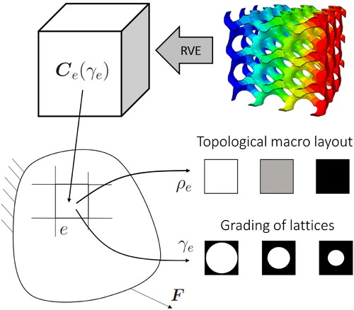
The effective elastic properties of each element e is obtained by numerical homogenization of representative volume elements (RVEs) of the TPMS-based lattice structure of interest such that the effective elasticity matrix in Voigt notation is given by
(1)
(1)
where
are material interpolation (regression) laws as function of the relative lattice density
of element e, where lb and ub are prescribed lower and upper limits on γe, respectively.
Typically, the lower limit lb represents the thinnest member that can be printed and ub is utilized for establishing practical removal of powder. Furthermore, cij in (EquationEq. 1(1)
(1) ) are the elastic properties of the bulk material of the lattice structure, which are assumed to be governed by transversely isotropic elasticity, i.e.,
(2)
(2)
where E and E33 are Young’s moduli, ν and ν13 are Poisson’s ratios and G23 is the out-of-plane shear moduli. Thus, the 3-direction is aligned with the building direction of the additive manufacturing process of the lattice and it is assumed that isotropic properties are obtained in the build plane.
Thus, each element e has unique linear orthotropic elastic properties, defined by in (EquationEq. 1
(1)
(1) ), which in turn depends on the relative lattice density γe. The stresses and strains, i.e.,
(3)
(3)
are, of course, governed by
and the corresponding local effective finite element stiffness matrix for element e is denoted by
(4)
(4)
In the global assembly procedure, the RAMP model is utilized in order to define if the finite element e should be considered to be a void or filled with lattice structure. Thus, the global stiffness matrix is generated by
(5)
(5)
where,
represents an assembly operator, n is the RAMP factor and
is the relative macro density of lattice structure for element e. Here,
implies a completely filled element with lattice structure and
represents a void. In the numerical implementation, the zero is replaced with a small number ϵ in order to avoid singular stiffness matrices. Instead of using the RAMP model, the established SIMP model can be adopted in (EquationEq. 5
(5)
(5) ), which then reads
(6)
(6)
The total volume of bulk material generated in the assembly procedure is given by
(7)
(7)
where Ve represents the total volume of each element e when
By using (EquationEq. 7
(7)
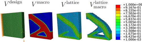
(7) ), the following different volume measures can be identified
(8)
(8)
where
is the total volume of the design domain,
is the total volume of the macro layout filled with lattice structure,
is the total volume of lattice in the design domain and
is a vector of ones. The volume of lattice in the macro layout of lattice structure
is given by
(9)
(9)
which will converge toward the volume of bulk material
because
in the void region.
and
are constrained separately in the multi-scale topology optimization formulation presented in (EquationEq. 14
(14)
(14) ) in the next section. The different volume measures introduced above in (EquationEq. 8
(8)
(8) ) and (EquationEq. 9
(9)
(9) ) using
in (EquationEq. 7
(7)
(7) ) are illustrated in for a standard benchmark solved by (EquationEq. 14
(14)
(14) ) using
and
Thus,
and (EquationEq. 9
(9)
(9) ) yields
(10)
(10)
Figure 2. Illustration of the different volume measures defined in (EquationEqs. 8(8)
(8) and Equation9
(9)
(9) ) by using the volume of bulk material in (EquationEq. 7
(7)
(7) ).
Consequently,
(11)
(11)
are used in (EquationEq. 14
(14)
(14) ).
From a engineering point of view, the following volume fractions are of interest, see also (EquationEq. 29(29)
(29) ):
(12)
(12)
where
is the fraction of bulk material in the design domain,
is the fraction of macro layout and
is the fraction of lattice in the macro layout. By starting from
inserting (EquationEq. 12
(12)
(12) ), one can derive
(13)
(13)
This relationship is utilized in the formulation of the benchmarks in the numerical study in Section 5, such that an upper limit on the bulk material can be given relative to the upper limits on and
used in (EquationEq. 14
(14)
(14) ).
3. Topology optimization, sensitivity analysis and filters
In this section, a new innovative multi-scale topology optimization formulation is proposed for minimizing the compliance of the design domain with one constraint on the macro layout volume and an additional constraint on the lattice volume
The new multi-scale formulation reads
(14)
(14)
where
is the displacement vector,
contains the external forces, c is the compliance,
is the static equilibrium equation,
and
are the upper limits on the macro layout volume and the lattice volume, respectively. The standard compliance problem is recovered by setting ub=1 and
and the local grading formulation for the whole design domain using effective elasticity properties, as presented in Strömberg (Citation2021a), is obtained by setting
By dividing the volume constraints in (EquationEq. 14(14)
(14) ) by
and utilizing (EquationEqs. 9
(9)
(9) , Equation12–14) can be rephrased to
(15)
(15)
The new multi-scale topology optimization problem in (EquationEq. 14(14)
(14) ) or (EquationEq. 15
(15)
(15) ) is solved using sequential linear programming (SLP) using the sensitivities and filters presented below. The sensitivities of the compliance c, using the adjoint method, are given by
(16)
(16)
(17)
(17)
where
(18)
(18)
and
(19)
(19)
where
are needed in (EquationEq. 19
(19)
(19) ).
The sensitivities of the volume and
are, of course,
(20)
(20)
The sensitivities are treated by a density filter for both ρe and γe (Bourdin Citation2001), and, in addition, ρe is passing a smooth Heaviside function (Wang, Lazarov, and Sigmund Citation2011). Thus, ρe is treated by
(21)
(21)
where
is the number of finite elements,
(22)
(22)
denotes the distance between the center of element e and f, and
is the filter radius, which is set to 1.5 times the characteristic length of the finite elements in the numerical examples. (EquationEq. 21
(21)
(21) ) is also applied on γe. Furthermore,
(23)
(23)
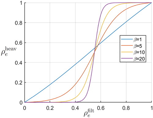
where η defines the threshold and β sets the slope of the smooth Heaviside filter. In the numerical examples,
β is ramped from 1 to 20, and the filter is activated after 50 SLP iterations. The Heaviside filter is depicted in for this setting of η and different values on β. The adoption of the smooth Heaviside filter implies a very thin layer of intermediate values between the void region with
and the lattice filled region with
see e.g., the thin layer of intermediate values in
presented in , see also the histogram of
presented in . In the post-processing made in this paper, intermediate values
are interpreted as a part of the region with TPMS-based lattice structure and
are treated as voids. This could of course be modified by using a threshold value closer to 1, but the post-processed results will look very similar because almost all intermediate values are efficiently removed by the Heaviside filter. The latter is also demonstrated in by studying the measure of discreteness defined in (EquationEq. 30
(30)
(30) ).
Figure 3. The smooth Heaviside filter in (EquationEq. 23(23)
(23) ) for
and different values on β.
Thus, in problem (EquationEq. 14(14)
(14) ), the stiffness and volumes are given as functions of
and
i.e.,
and
The sensitivities in (EquationEqs. 16–20) are then calculated using the chain rule, e.g.,
(24)
(24)
4. The Gyroid lattice structure
The proposed multi-scale topology optimization framework is demonstrated in the next section by using the frame-based Gyroid lattice structure, which is formulated as an implicit-based surface, i.e.,
(25)
(25)
where ω is controlling the size of the period and
is the scalar level controlling the relative density of the lattice. A cube of 1x1x1 periods of the frame-based Gyroid lattice (
) for
is depicted in grey in . The corresponding shell-based Gyroid lattice structure was considered in Strömberg (Citation2021a).
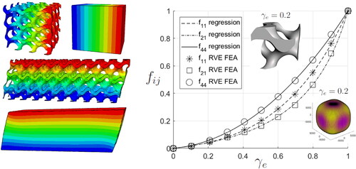
Figure 4. The material interpolation laws fij for the frame-based Gyroid structure obtained by numerical homogenization of RVEs for prescribed normal strains and simple shear strains. The markers represent the results from the finite element analysis of the RVEs.
The effective elastic properties of the lattice are obtained by using linear finite element analysis (FEA) using Abaqus/Standard of RVEs subjected to 3 prescribed normal strains, e.g., and 3 prescribed simple shear strains, e.g.,
in orthogonal directions. The corresponding stresses are then given by
e.g.,
and
The RVE used for the prescribed normal strains is a cube with 3x3x3 periods of the Gyroid cell, and the simple shear strains are treated using a rectangular cuboid with 9x3x3 periods of the Gyroid cell in order to reduce the influence of the free boundaries, see . Approximately, 2 million linear tetrahedral elements are used for the 3x3x3 cube and 6 million elements for the 9x3x3 cuboid. This numerical homogenization approach is simple and straight-forward to implement (see e.g., Steven Citation1997 and Li, Dai, et al. Citation2019) and the computational time is only few minutes for each RVE on a PC workstation. An alternative treatment that would speed up the computational time would be to use a single periodic cell as presented in grey in with periodic boundary conditions (see e.g., Omairey, Dunning, and Sriramula Citation2019).
From the numerical homogenization, it is clear that the lattice exhibits cubic symmetric behavior, although the geometry has no cubic symmetry, see this by rotating the Gyroid cell depicted in grey in by 90 degrees. The cubic behavior of the Gyroid structure appears clearly when Young’s modulus is plotted in different directions in a polar plot, an example of such polar plot of Young’s modulus is found in the lower right corner of for γe=0.2.
As a result from the procedure above, see also Strömberg (Citation2021a), the effective elastic matrix for the frame-based Gyroid structure is given by
(26)
(26)
where the material interpolation laws
are presented in . These functions are given as the following convex combination of RAMP and SIMP basis functions:
(27)
(27)
where
are regression coefficients presented in . Concerning regression models with convex combination constraints, see e.g., Strömberg (Citation2021b).
Table 1. The regression coefficients for the material interpolation laws fij in (EquationEq. 27(27)
(27) ) for the frame-based Gyroid structure.
5. Numerical examples
The proposed multi-scale topology optimization approach is implemented and demonstrated in this section for the frame-based Gyroid lattice structure presented in the previous section. The implementation is done in our in-house toolbox, TopoBox, using Matlab and Fortran. The pre- and post-processing of models and results are done in Abaqus/CAE.
A three-dimensional L-shaped benchmark similar to the one presented by Borrvall and Petersson (Citation2001) is considered for different settings using the implementation. The design domain is presented in , which is discretized using 157946 linear tetrahedral elements. The four corners of the back-side is fixed and the lower opposite corner is subjected to a single vertical force Fz or a weighted load case using Fx, Fy and Fz with equal magnitudes and equal weights. Young’s modulus and Poisson’s ratio for the isotropic bulk material is 2.1E5 N/mm2 and 0.3, respectively. Notice that this benchmark includes both bending and torsion.
Figure 5. The L-shaped design domain subjected to a single load case Fz or a weighted load case (Fx, Fy, Fz). The compliance for the single load case is compared using no grading or optimal grading.
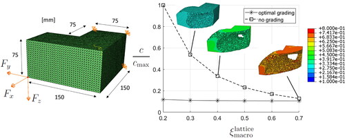
The L-shaped benchmark is first studied by only optimizing the macro-layout for almost constant relative density of the lattice structure and constant volume of bulk material. This is done by the formulation in (EquationEq. 14(14)
(14) ) by setting
[0.2:0.1:0.7], and
and
where 0.025 is the move limit step in the SLP algorithm. By using (EquationEq. 13
(13)
(13) ), the corresponding values on
are [1.0000,0.6667, 0.5000,0.4000,0.3333,0.2857]. The optimal compliance c as function of
is plotted in . The compliance c is normalized with the maximum value obtained for
=0.2, denoted
The density solutions
for elements with
are also plotted in , this is done for
=0.3, 0.4 and 0.7. These solutions are similar to the one presented in Borrvall and Petersson (Citation2001). Observe that the bulk material is constant for all solutions presented in . The same is true for the results presented next in and .
Figure 6. Optimal combinations of macro-layouts and local gradings for the L-shaped benchmark subjected to a single load case.
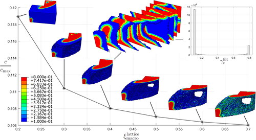
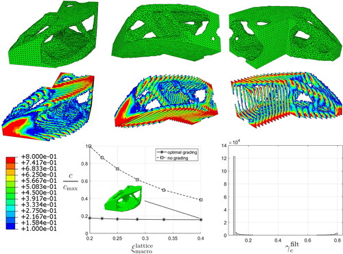
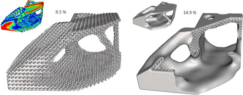
Figure 7. The weighted compliance for the L-shaped benchmark with and without local grading. A crisp macro-layout and the corresponding local grading are plotted for different views.
Next, optimal local grading is included by modifying the above setting by letting lb=0.1 and ub=0.8. The obtained optimal compliance as function of is also plotted in using the same normalization in order to compare the results with the results obtained previously using no grading. A significant improvement in compliance is observed for
0.6. For
=0.2, the improvement is almost a factor of 10. For
0.6, both curves are converging toward each other as expected. The results obtained for the optimal grading are studied in more detail in , where the density solutions
are plotted on elements with
as previous. For
=0.4, the density plot is also sliced and the corresponding histogram of
is depicted. It is clear for the single load case that the majority of all values on
converge toward the lower and upper limit, lb and ub, respectively. This is explained by the material interpolation laws fij that penalize intermediate values in a similar way as SIMP and RAMP, see . One should also observe the small difference obtained in the compliance for the different volumes of macro layout when optimal grading is included. The highest and lowest compliance values only differ 12.3%.
The L-shaped benchmark is also considered for the weighted compliance problem using with equal magnitudes and equal weights in the formulation of the compliance. That is, (EquationEq. 14
(14)
(14) ) is solved for three equilibrium equations
(i = 1,2,3) and
(28)
(28)
Now, and solutions are generated for
[0.25:0.05:0.5], i.e., [0.4,0.3333,0.2857,0.25,0.222,0.2]. Again, the solutions using optimal grading are significantly better than the solutions obtained for constant lattice density, see . For
=0.2, the optimal graded solution is approximately 5 times better, and, for
=0.4, more than 2 times better. The densities for the solution with lowest compliance is also plotted in . The optimal macro layout defined by
0.6 is plotted in green for three different views. The optimal grading
is then plotted and sliced on this macro layout. In addition, the histogram of
is presented at the lower right corner of .
As can be seen from the plots in , a crisp macro layout plotted in green is obtained, although the weighted compliance of three load cases is solved for only 10% bulk material. This might be explained by the intermediate values appearing in the local grading solution Still, the number of elements with intermediate values is low, which can be seen from the histogram plot. Thus, most values of
still converge toward the lower and upper limit, lb and ub, respectively.
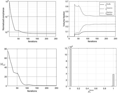
For the optimal solution presented in , the convergence of the weighted compliance normalized by the initial compliance value, the volume fractions in (EquationEq. 29(29)
(29) ) and the measure of discreteness introduced by Sigmund (Citation2007) are plotted in . In particular, the convergence of the volume fractions in (EquationEq. 12
(12)
(12) ) are studied for three different thresholds on
=0.95, 0.6 and 0 such that the volume fractions in (EquationEq. 12
(12)
(12) ) are numerically evaluated as
(29)
(29)
Figure 8. Convergence in weighted normalized compliance (0.0078), volume fractions and measure of discreteness. The corresponding histogram of is also plotted.
Notice, that (EquationEq. 12(12)
(12) ) is recovered from (EquationEq. 29
(29)
(29) ) when ρt=0. Furthermore, by following Sigmund (Citation2007), the measure of discreteness is defined by
(30)
(30)
In , the convergence of the volume fractions in (EquationEq. 29(29)
(29) ) are plotted for
where
and
converge to 0.0992, 0.247 and 0.402, respectively. By switching the threshold from ρt=0.95 to ρt=0.6 in (EquationEq. 29
(29)
(29) ), one obtains instead 0.0995, 0.249 and 0.400, respectively, and if
in (EquationEq. 29
(29)
(29) ), then one gets as expected 0.1, 0.25 and 0.4, respectively, which correspond to the prerequisites of the problem. The converged values obtained for these three different thresholds on
are indeed very similar. The explanation for this is that the smooth Heaviside filter in (EquationEq. 23
(23)
(23) ) efficiently removes almost all intermediate densities. This can also be seen by studying
and the histogram of
in .
converges to 0.68%, which is just slightly larger than the values reported by Sigmund (Citation2007) for the 2 D MBB test example using two different Heaviside filters. By studying the convergence plots, one clearly observes the effect of the Heaviside filter on the compliance, the volume fractions and
when it is activated after 50 iterations.
The optimal combinations of macro layouts and local gradings
can be converted to implicit-based geometries, which in turn can be exported to stl-files using marching cubes. A procedure for this is presented in (Strömberg Citation2019), which involves the following steps:
The macro-layout solution
is converted to an implicit-based surface
The local grading solution
A thin cover for the lattice designs can be generated by
The final engineering design is then obtained by
Figure 9. Stl-files of the optimal solution for the L-shaped benchmark by using implicit-based geometry. The cut of the design is done in order to show the lattice inside the cover.
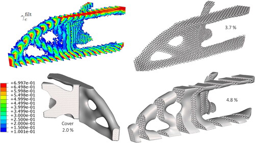
By using the proposed multi-scale framework, ultra-lightweight design of graded TPMS-based structures can easily be generated. This is demonstrated for the L-shaped benchmark for the single load case with =0.1 and
=0.35, implying
as low as 0.035. The multi-scale results and the corresponding design as stl-files are presented in . The relative lattice density
is plotted on elements with
0.6 in the upper left corner of the figure. The corresponding graded frame-based Gyroid structure is plotted to the right. Again, the grading appears clearly by zooming. A cover is then generated and added to the lattice. The corresponding final design with cover is depicted sliced in the figure. The volume fraction of the cover is 2% taken separtely, but it is only adding 1.1% extra volume when the union of the lattice is performed. Thus, the total volume of bulk material is only 4.8% of the original design domain, which is considered to be an ultra-lightweight design, see e.g., Zhang, Sato, and Yanagimoto (Citation2021). If no grading is included for this setting of the benchmark, then the compliance increases a factor of 2 and the macro layout becomes less crisp.
Figure 10. A ultra-lightweight design of the L-shaped benchmark for a single load case.
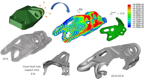
As an illustration of a real engineering application, the design domain of the established GE-bracket is optimized for a weighted load case of three orthogonal directions of forces acting on the hole of the pin and fixed at the four bolt holes, see . The optimal combination of macro layout and local grading for =0.25 and
=0.4, implying 10% bulk material, are solved using (EquationEq. 14
(14)
(14) ). The obtained optimal combinations of density solutions
and
are presented in . In particular,
is plotted on elements with
0.6 and then sliced. The macro layout defined by
0.6 is also plotted in green. By transferring the density solutions to implicit based geometry as discussed above, the corresponding stl-file is generated and presented to the left in . In addition, a thin cover is added using Boolean operations in order to a obtain a robust engineering design presented to the center and the right of .
Figure 11. Optimal combination of macro-layout and local graded frame-based Gyroid structure for the well-known GE-bracket.
6. Concluding remarks
In this paper, a new innovative multi-scale topology optimization framework for generating optimal combinations of macro-layouts and local graded TPMS-based lattice structures is proposed and implemented. The formulation is done by introducing two density variables, one for defining the macro layout and the other one defining the relative density of the lattice structure. The density for the macro layout is governed by RAMP and the relative density of the lattice structure is governed by effective elastic properties obtained by numerical homogenization of representative volume elements of the TPMS-based lattice. By solving benchmarks in 3 D using the proposed implemented formulation, it is demonstrated that optimal designs of macro-layouts with graded Gyroid structures are generated that are significantly stiffer than the corresponding optimal designs using constant lattice densities. It is also shown that the difference in compliance for designs with different volume fractions of macro layouts is small when local grading is performed. Furthermore, the optimal macro-layouts are typically crisp even for multiple load cases, and by combining low volume fractions of macro-layout and lattice structure, designs with low volume of bulk material are easily generated. In conclusion, the proposed multi-scale topology optimization formulation for optimal combinations of macro layouts and local graded TPMS-based lattice structures is most promising for generating ultra-lightweight designs for additive manufacturing. Even if the stiffness becomes slightly lower than the stiffness obtained for a corresponding optimal solid structure without lattices, the optimal lattice design might be beneficial from other aspects such as buckling loads and frequency response. To include these kind of aspects in the presented framework is a topic of future research.
Disclosure statement
The author declares that he has no conflict of interest.
Additional information
Funding
References
- Allaire, G., P. Geoffroy-Donders, and O. Pantz. 2019. Topology optimization of modulated and oriented periodic microstructures by the homogenization method. Computers & Mathematics with Applications 78 (7):2197–229. doi: 10.1016/j.camwa.2018.08.007.
- Borrvall, T, and J. Petersson. 2001. Large-scale topology optimization in 3d using parallel computing. Computer Methods in Applied Mechanics and Engineering 190 (46–47):6201–29. doi: 10.1016/S0045-7825(01)00216-X.
- Bourdin, B. 2001. Filters in topology optimization. International Journal for Numerical Methods in Engineering 50 (9):2143–58. doi: 10.1002/nme.116.
- Cheng, L., J. Bai, and A. C. To. 2019. Functionally graded lattice structure topology optimization for the design of additive manufactured components with stress constraints. Computer Methods in Applied Mechanics and Engineering 344:334–59. doi: 10.1016/j.cma.2018.10.010.
- Cheng, L., X. Liang, E. Belski, X. Wang, J. M. Sietins, S. Ludwick, and A. To. 2018a. Natural frequency optimization of variable-density additive manufactured lattice structure: Theory and experimental validation. Journal of Manufacturing Science and Engineering 140 (10):105002. doi: 10.1115/1.4040622.
- Cheng, L., J. Liu, X. Liang, and A. C. To. 2018b. Coupling lattice structure topology optimization with design-dependent feature evolution for additive manufactured heat conduction design. Computer Methods in Applied Mechanics and Engineering 332:408–39. doi: 10.1016/j.cma.2017.12.024.
- Daynes, S., S. Feih, W. F. Lu, and J. Wei. 2017. Optimisation of functionally graded lattice structures using isostatic lines. Materials & Design 127:215–23. doi: 10.1016/j.matdes.2017.04.
- Jansen, M, and O. Pierard. 2020. A hybrid density/level set formulation for topology optimization of functionally graded lattice structures. Computers & Structures 231:106205. doi: 10.1016/j.compstruc.2020.106205.
- Jin, X., G. X. Li, and M. Zhang. 2018. Optimal design of three-dimensional non-uniform nylon lattice structures for selective laser sintering manufacturing. Advances in Mechanical Engineering 10 (7):168781401879083–19. doi: 10.1177/1687814018790833.
- Li, D., N. Dai, Y. Tang, G. Dong, and Y. F. Zhao. 2019. Design and optimization of graded cellular structures with triply periodic level surface-based topological shapes. Journal of Mechanical Design 141 (7):071402. doi: 10.1115/1.4042617.
- Li, D., W. Liao, N. Dai, and Y. M. Xie. 2019. Comparison of mechanical properties and energy absorption of sheet-based and strut-based Gyroid cellular structures with graded densities. Materials 12 (13):2183. doi: 10.3390/ma12132183.
- Li, D., W. Liao, N. Dai, and Y. M. Xie. 2020. Anisotropic design and optimization of conformal gradient lattice structures. Computer-Aided Design 119:102787. doi: 10.1016/j.cad.2019.102787.
- Liu, J., A. T. Gaynor, S. Chen, Z. Kang, K. Suresh, A. Takezawa, L. Li, J. Kato, J. Tang, C. C. L. Wang, et al. 2018. Current and future trends in topology optimization for additive manufacturing. Structural and Multidisciplinary Optimization 57 (6):2457–83. doi: 10.1007/s00158-018-1994-3.
- Liu, P., Z. Kang, and Y. Luo. 2020. Two-scale concurrent topology optimization of lattice structures with connectable microstructures. Additive Manufacturing 36:101427. doi: 10.1016/j.addma.2020.101427.
- Liu, L., J. Y. Yan, and G. Cheng. 2008. Optimum structures with homogenous optimum truss-like material. Computers & Structures 86 (13-14):1417–25. doi: 10.1016/j.compstruc.2007.04.030.
- Maskery, I., L. Sturm, A. O. Aremu, A. Panesar, C. B. Williams, C. J. Tuck, R. D. Wildman, I. A. Ashcroft, and R. J. M. Hague. 2018. Insights into the mechanical properties of several triply periodic minimal surface lattice structures made by polymer additive manufacturing. Polymer 152:62–71. doi: 10.1016/j.polymer.2017.11.049.
- Nazir, A., K. M. Abate, A. Kumar, and J.-Y. Jeng. 2019. A state-of-the-art review on types, design, optimization and additive manufacturing of cellular structures. The International Journal of Advanced Manufacturing Technology 104 (9–12):3489–510. doi: 10.1007/s00170-019-04085-3.
- Omairey, S., P. D. Dunning, and S. Sriramula. 2019. Development of an ABAQUS plugin tool for periodic RVE homogenisation. Engineering with Computers 35 (2):567–77. doi: 10.1007/s00366-018-0616-4.
- Panesar, A., M. Abdi, D. Hickman, and I. Ashcroft. 2018. Strategies for functionally graded lattice structures derived using topology optimization for additive manufacturing. Additive Manufacturing 19:81–94. doi: 10.1016/j.addma.2017.11.008.
- Plocher, J, and A. Panesar. 2018. Review on design and structural optimization in additive manufacturing: Towards next generation lightweight structures. Materials and Design 183. doi: 10.1016/j.matdes.2019.108164.
- Rodrigues, H., J. M. Guedes, and M. P. Bendsø. 2002. Hierarchical optimization of material and structures. Structural and Multidisciplinary Optimization 24 (1):1–10. doi: 10.1007/s00158-002-0209-z.
- Schoen, A. H. 1970. Infinite Periodic Minimal Surfaces without Self-Intersections NASA Technical Note TN D-5541.
- Seharing, A., A. H. Azman, and S. Abdullah. 2020. A review on integration of lightweight gradient lattice structures in additive manufacturing parts. Advances in Mechanical Engineering 12 (6):168781402091695–21. doi: 10.1177/1687814020916951.
- Shepard, D. 1968. A two-dimensional interpolation function for irregularly-spaced data. In The proceedings of the 23rd ACM national conference, 517–524. doi: 10.1145/800186.810616.
- Sigmund, O. 2007. Morphology-based black and white filters for topology optimization. Structural and Multidisciplinary Optimization 33 (4-5):401–24. doi: 10.1007/s00158-006-0087-x.
- Steven, G. P. 1997. Homogenization of multicomponent composites orthotropic materials using FEA. Communications in Numerical Methods in Engineering 13 (7):517–31. doi: 10.1002/(SICI)1099-0887(199707)13:7<517::AID-CNM74>3.0.CO;2-L.
- Stolpe, M, and K. Svanberg. 2001. An alternative interpolation scheme for minimum compliance topology optimization. Structural and Multidisciplinary Optimization 22 (2):116–24. doi: 10.1007/s00158010012.
- Strömberg, N. 2019. A generative design optimization approach for additive manufacturing. In The Proceeding of 2nd International Conference on Simulation for Additive Manufacturing, Sim-AM, 130–41. Pavia, 11–13 September.
- Strömberg, N. 2019. Efficient detailed design optimization of topology optimization concepts by using support vector machines and metamodels. Engineering Optimization 52 (7):1–1148. doi: 10.1080/0305215X.2019.1646258.
- Strömberg, N. 2021a. Optimal grading of TPMS-based lattice structures with transversely isotropic elastic bulk properties. Engineering Optimization 53 (11):1871–83. doi: 10.1080/0305215X.2020.1837790.
- Strömberg, N. 2021b. Comparison of optimal linear, affine and convex combinations of metamodels. Engineering Optimization 53 (4):702–18. doi: 10.1080/0305215X.2020.1746781.
- Takezawa, A., A. C. To, Q. Chen, X. Liang, F. Dugast, X. Zhang, and M. Kitamura. 2020. Sensitivity analysis and lattice density optimization for sequential inherent strain method used in additive manufacturing process. Computer Methods in Applied Mechanics and Engineering 370:113231. doi: 10.1016/j.cma.2020.113231.
- Vicente, W. M., Z. H. Zuo, R. Pavanello, T. K. L. Calixto, R. Picelli, and Y. M. Xie. 2016. Concurrent topology optimization for minimizing frequency responses of two-level hierarchical structures. Computer Methods in Applied Mechanics and Engineering 301:116–36. doi: 10.1016/j.cma.2015.12.012.
- Wang, Y, and Z. Kang. 2019. Concurrent two-scale topological design of multiple unit cells and structure using combined velocity field level set and density model. Computer Methods in Applied Mechanics and Engineering 347:340–64. doi: 10.1016/j.cma.2018.12.018.
- Wang, F., B. S. Lazarov, and O. Sigmund. 2011. On projection methods, convergence and robust formulations in topology optimization. Structural and Multidisciplinary Optimization 43 (6):767–84. doi: 10.1007/s00158-010-y.
- Wang, Y., L. Zhang, S. Daynes, H. Zhang, S. Feih, and M. Y. Wang. 2018a. Design of grade lattice structure with optimized mesostructures of additive manufacturing. Materials & Design 142:114–23. doi: 10.1016/j.matdes.2018.01.011.
- Wang, X., P. Zhang, S. Ludwick, E. Belski, and A. C. To. 2018b. Natural frequency optimization of 3d printed variable-density honeycomb structure via a homogenization-based approach. Additive Manufacturing 20:189–98. doi: 10.1016/j.addma.2017.10.001.
- Wu, J., O. Sigmund, and J. P. Groen. 2021. Topology optimization of multi-scale structures: A review. Structural and Multidisciplinary Optimization 63 (3):1455–80. doi: 10.1007/s00158-021-02881-8.
- Zhang, Y., L. Gao, and M. Xiao. 2020. Maximizing natural frequencies of inhomogeneous cellular structures by Kriging-assisted multiscale topology optimization. Computers & Structures 230:106197. doi: 10.1016/j.compstruc.2019.106197.
- Zhang, P., J. Liu, and A. C. To. 2017. Role of anisotropic properties on topology optimization of additive manufactured load bearing structures. Scripta Materialia 135:148–52. doi: 10.1016/j.scriptamat.2016.10.021.
- Zhang, J., Y. Sato, and J. Yanagimoto. 2021. Homogenization-based topology optimization integrated with elastically isotropic lattices for additive manufacturing of ultralight and ultrastiff structures. CIRP Annals 70 (1):111–4. doi: 10.1016/j.cirp.2021.04.019.
- Zhang, P., J. Toman, Y. Yu, E. Biyikli, M. Kirca, M. Chmielus, and A. C. To. 2015. Efficient design-optimization of variable-density hexagonal cellular structure by additive manufacturing: Theory and validation. Journal of Manufacturing Science and Engineering 137 (2):021004. doi: 10.1115/1.4028724.