Abstract
In this paper, a numerical formulation was developed to generate the consistent mass matrix for Timoshenko tapered beam-column element for geometrically nonlinear transient analysis. The basis of the suggested solution is the exact shape functions and their derivatives, which describe the non-uniformity of the element properties. To illustrate the variations in section properties along the tapered element length, the section properties were presented as exponential functions with tapering indices. The model can simulate elements with various solid and hollow cross-sections. The suggested formulation is integrated into a Visual Basic program to perform the analysis, along with numerous examples to verify its precision and effectiveness. As a practical application of the proposed formulation, a structural system was proposed for offshore wind turbines with high elevations, and a geometrical nonlinear dynamic analysis was conducted. The results demonstrated the proposed model’s ability to perform this type of complex calculation with minimal computational effort.
Acknowledgments
The authors would like to thank the Geotec Office team for their contributions to developing the program used in this study, especially Prof. Dr. Mohamed El Gendy for his crucial efforts in this program.
Data availability statement
Data sharing is not applicable to this article as no new data were created or analyzed in this study.
Disclosure statement
The authors report there are no competing interests to declare.
Figure 16. Hub lateral displacement for cases from (E-1) to (E-4).
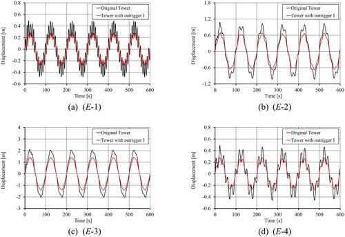
Figure 17. Base fore-aft bending moment for cases from (E-1) to (E-4).
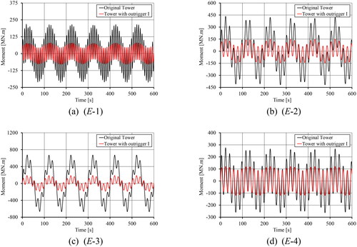
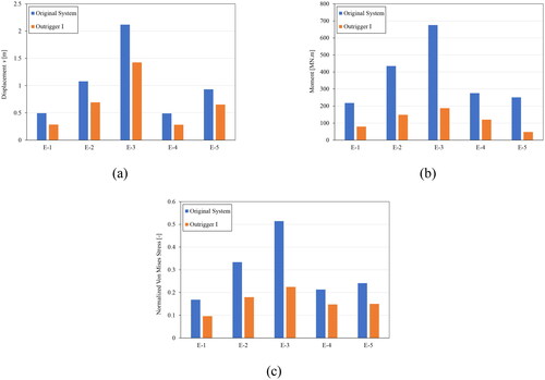
Figure 18. Comparison between the maximum results of: (a) the hub lateral displacement, (b) the base fore-aft bending moment, (c) the normalized Von Mises stress.