ABSTRACT
Singular optics is an emerging field, in which an optical wave with a helical wavefront is handled for optical manipulation and nanofabrication. We present a method to generate optical vortices via reflection from cholesteric liquid crystals with planar alignment. Numerical and experimental results show that the device is operable at multiple wavelengths with theoretically high conversion efficiency (lossless) without requiring fine-control of retardation. Although the operational wavelength range is limited by the birefringence and helix pitch of the material, broadband operation is possible by expanding the reflection band width by either introducing a pitch distribution or stacking multiple devices.
1. Introduction
An optical vortex has a helical wavefront with a phase singularity, around which the phase of light continuously changes by 2ℓπ, where ℓ is an integer. ℓ indicates the intensity of the vortex twist and is called the topological charge Citation[1, 2]. Optical vortices are conventionally generated using retardation plates or holograms Citation[3–5]; however, there remain challenges in that the device is commonly operable only at a single wavelength and/or it requires precise fabrication and control of retardation. For practical applications of optical vortices, facile and robust means of beam generation is still much in need.
In this study, we describe optical vortex generation from a cholesteric liquid crystal (ChLC). ChLC is a liquid crystalline phase in which rod-shaped molecules self-organise into a helical structure. Owing to the periodic perturbation of the dielectric constant along its helical axis, ChLCs are known to show circular-polarisation selective reflection, whereby circularly polarised light with the same rotation sense as the helix is totally reflected within the wavelength range given by nop−nep, where no and ne are the ordinary and extraordinary refractive indices, respectively, and p is the helical pitch Citation[6]. Recently, we reported that the reflected wavefront can be moulded into arbitrary shapes by changing the helix phase of ChLC depending on the position Citation[7, 8]. This phenomenon is referred to as the chiral geometric Berry-phase effect Citation[9]. Based on this concept, we previously reported numerical and experimental evidence that an optical vortex generator that is operable at multiple wavelengths, with higher conversion efficiency, and without requiring the control of retardation can be fabricated Citation[10]. However, in the previous study, the number of topological charges was limited to 1 and 2. A larger number of topological charges would be potentially useful in the field of quantum computation, because the amount of information can be increased Citation[11]. Here, we describe the numerical background in detail and experimentally demonstrate optical vortices with higher topological charges. Moreover, we demonstrate broadband optical vortex generation by introducing a pitch distribution inside the cell, along the direction of the helical axis.
2. Theoretical analysis of light reflection by cholesteric liquid crystals
In this section, we theoretically investigate the reflection phase of light from a ChLC with an arbitrary helix phase, based on coupled-mode theory Citation[6] and Berreman's 4 × 4 matrix method Citation[12].
2.1. Analytical solution according to coupled-mode theory
We first analytically solve for the complex reflection coefficient of light from ChLCs based on a perturbation analysis Citation[6]. Consider that a helical axis of a right-handed ChLC is parallel to the z-axis and light propagates along the helical axis. The dielectric tensor of the helical structure is given by
(1) where
, q = 2π/p, and ϕ is the helix phase. The second term is the dielectric perturbation, which can be rewritten as
(2)
The presence of the perturbation Δϵ gives rise to a dielectric polarisation given by Citation[6]
(3)
By calculating ΔP for an incident wave Ei with various polarisation states, one finds that the perturbation term ΔP is always right-handed circularly polarised (RCP).
Consider that the total electric field of both incident and reflected RCP light is written as
(4) where A(z) and B(z) are the amplitudes of the two waves and k = 2πϵ1/2/λ.
According to coupled-mode theory, the coupled wave equations for the two modes propagating in opposite directions are given by Citation[6]
(5)
where Δk = 2(k − q) is the Bragg condition and κ is the coupling coefficient for RCP light. κ is given by
(6)
After some calculation with boundary conditions A(0) = 1 and B(L) = 0 (L is the length of helix), we obtain the following solutions Citation[6]:
(7) and
(8) where s2 = κκ* − (Δk/2)2.
The reflection coefficient ρ, and subsequently the reflectance R and phase of reflected light Φr from the helix are expressed as follows Citation[10]:
(9)
(10) and
(11)
Note that for reflected light, a decrease in Φr corresponds to an advance in phase. From Eq. Equation11(11) , we find that independent of the wavelength, the change in the reflection phase is twice that in the helix phase. In other words, the geometrical phase effect is applicable to multiple wavelengths, although practically, it is useful in the wavelength range inside the total reflection band.
2.2. Numerical solution according to Berreman's 4 × 4 matrix method
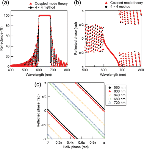
We can explore a numerical solution of light propagation in ChLC according to Berreman's 4 × 4 matrix method Citation[12]. This well-known method is proven to show good agreement with experimental results. To prove the correctness of the analytical solution in the previous section, we performed a calculation on ChLC upon normal incidence, assuming a helical structure with parameters shown in .
Table 1. Parameters for numerical calculation.
shows the reflection spectra of right-handed polarised light upon normal incidence at helix phase 0. The reflection band appeared between 600 and 680 nm, which is given by nop−nep. shows the reflection phase of p-polarised light at helix phase 0. The reflection phase changed, depending on the wavelength. In both figures, the red triangles and black circles indicate the analytical (coupled-mode theory) and numerical (Berreman's 4 × 4 matrix method) solutions, respectively. The two calculation results show good agreement in a wavelength range not only in the reflection band, where Bragg's law is satisfied, but also outside of the reflection band, which confirms that Eqs. Equation10(10) and Equation11
(11) yield a well-approximated solution. shows the reflection phase at various wavelengths (calculated by the 4 × 4 matrix method). The linear relationship between the reflected and helix phases is maintained at multiple wavelengths within the reflection band; hence, reflection phase control can be achieved at polychromatic wavelengths.
3. Optical vortex generation from patterned cholesteric liquid crystals
Based on the theoretical analyses described in the previous section, many kinds of reflective optical elements, such as deflectors, lenses, and optical vortex generators, can be demonstrated using ChLCs Citation[7, 10]. In this section, we experimentally show an optical vortex generator with photopatterned ChLCs with higher topological charges ℓ from 4 to 12 (charges of ℓ = 1, 2 have been demonstrated previously Citation[10]). A plane wavefront of circularly polarised light with the same helicity as ChLC is completely converted into an optical vortex upon reflection.
3.1. Sample fabrication
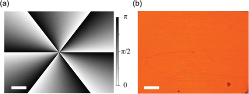
Two glass substrates coated with azobenzene-based photoalignment agent (LIA-03, DIC) were assembled into a 9-μm-thick LC cell. Orientation easy axis control at the surface of the substrates was performed using a maskless polarised light projection setup described elsewhere Citation[7, 8]. The easy axis distributions with a phase singularity with topological charge ℓ = 4, 6, 8, and 12, which is given by ϕ = 0.5ℓ tan−1(y/x), were fabricated (). Surface alignment control was performed with step-by-step irradiation of linearly polarised light (436 nm, 34 mW/cm2) for 60 s. A right-handed ChLC material, exhibiting a reflection band between 580 and 680 nm, was injected into the cell, which was composed of a nematic LC (BL-006, Merck) and chiral dopant (CD-X, Merck) in a weight ratio of 96.3:3.7.
3.2. Sample observation
The texture of the cell was observed with a polarised optical microscope (Eclipse LV100 POL, Nikon). In addition, the reflection phase distribution was visualised using a Michelson-type interferometric microscope with a white light source. The reflected light intensity profile was also evaluated to confirm optical vortex generation. A collimated He-Ne laser was normally incident to the sample after passing through a non-polarising beam splitter, and the light reflected from the sample was directly collected by a CCD camera. An optical isolator composed of a polariser and a quarter wave plate was inserted to block unwilling Fresnel reflected light. A lens and an aluminium mirror were inserted into the other path of the beam splitter for interferometric observation.
3.3. Results and discussion
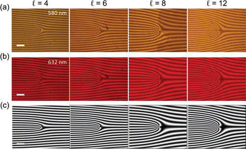
shows a typical polarised microscope image of the sample with ℓ = 6. A Grandjean texture of ChLC was observed with a screw disclination at the centre of the patterned area. show interferograms of each sample at multiple wavelengths (580 and 633 nm). A fork-like interference fringe, which characterises the helical wavefront, was observed independent of the wavelength, confirming the polychromatic feature that is expected from Eq. Equation11(11) and . The number of branches in the fork fringes increases with increasing topological charge. shows simulated interferograms of the fork-shaped fringes, assuming that the interferogram (|Ψ1+Ψ2|2) between the phase front of the signal wave and the tilted reference wave is described by Ψ1(x,y) = exp[iΦr(x,y)] and Ψ2(x,y) = exp[−i(ky+Φ0)], where k is the wave vector corresponding to the tilt and Φ0 is the relative phase. The calculated results reproduced the experimental results well. The parameters (k, Φ0) for each figure are (−0.109,−π), (−0.118, −0.5π), (−0.082, 0.5π), and (−0.105, 0.1π).
Figure 3. Experimental interferograms of the sample at different wavelengths: (a) 580 nm and (b) 633 nm. (c) Simulated interferogram. Scale bar: 200 μm.
shows the reflected light spot of the sample with ℓ = 4. A bright annular intensity profile was observed upon right-handed polarised (RCP) light incidence, because the sample has selectivity for circularly polarised light. Hence, no reflection was observed upon left-handed polarised (LCP) light incidence (). shows an interferogram of the reflected light spot. An outgoing spiral interference fringe, which characterises the helical wavefront, was observed. The number of arms and helicity of the spiral indicates that the topological charge of the optical vortex is +4. shows a simulated interferogram of the reflected light spot, showing good agreement with the experimental result.
4. Broadband optical vortex generation
We have shown in the previous section that optical vortices can be generated utilising patterned ChLC. Although the device is polychromatic and possesses high conversion efficiency, the operation wavelength is limited to 100 nm, not the whole visible range Citation[8]. Although Rafayelyan and Brasselet have recently reported that the broadband q-plates can be fabricated using the same concept over the full visible domain Citation[13], the reflectance outside the reflection band is too small for practical usage. The operation wavelength is determined by the reflection bandwidth of ChLC, given by Δλ = Δnp, where Δn is the birefringence of LC, which is usually less than 0.3. Some high-birefringence materials (Δn > 0.5) have been reported Citation[14]; however, they are typically unstable and present difficulties for practical use. Successful approaches to increase the bandwidth include ChLC with pitch gradient induced by thermal control, slow polymerisation of photocurable monomers, and stacking multiple ChLC films with various pitches Citation[15–17]. Here, we numerically and experimentally demonstrate that the geometric phase effect can be applied even when ChLCs have a non-uniform pitch distribution. We assumed two conditions of white reflection ChLC that are easily available: (Equation1(1) ) ChLC with pitch gradient and (Equation2
(2) ) stacked ChLC layers with different helix pitches.
4.1. Theoretical background
First, we show the theoretical background of the concept of using Berreman's 4 × 4 matrix method Citation[12]. Suppose that the refractive indices of the local director in a helical structure are ne = 1.8 and no = 1.5 (Δn = 0.3), and a cell is assembled by refractive index-matched glass substrates with nglass = 1.65 separated by approximately 15 μm. A right-handed ChLC with pitch distributions along the cell normal direction (z-direction) is filled inside the cells. shows the pitch distribution of two cells for calculation. The pitch is (Equation1(1) ) continuously and linearly varied along the z-axis from 240 to 430 nm, depending on the position, and (Equation2
(2) ) discretely changed from 270 to 325 to 390 nm, where each layer has 15 helix turns.
Figure 5 (a) Pitch distribution along the cell normal direction. (b) Two-dimensional plot of reflectance. Left: gradient pitch; right: stacked layers. (c) Two-dimensional plot of reflection phase. (d) Reflection phase at various wavelengths.
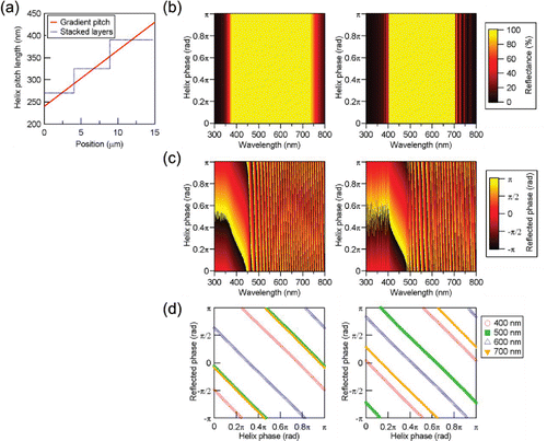
shows the calculated reflectance of the two cells. The horizontal and vertical axes show the wavelength and helix phase, respectively, and the colour indicates the reflectance. For RCP light incidence, each cell showed broadband a total reflection band in the whole visible range from 400 to 700 nm. The cells with pitch gradient also possess selectivity for circularly polarised light (LCP light is not reflected; not shown here). show the phase of reflected light of the two cells. For each cell, the reflection phase changed in proportion to the helix phase, regardless of the wavelength within the reflection band (). These results indicate that the geometric phase effect can be expected regardless of the pitch distribution; in other words, one needs to consider the reflectance rather than the pitch distribution within the cell.
4.2. Experimental results and discussion
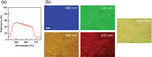
In order to confirm the validity of the calculation, a ChLC cell with pitch distribution was prepared using a polymer-stabilisable ChLC material. The material used here comprised of a nematic liquid crystal (Merck, MLC-2140), mesogen monomer (Merck, RMM141C), chiral dopant (Merck, CD-X), photoinitiator (Irgacure 819, Ciba), and UV-absorbing dye (PBBO: 2-(4-Biphenylyl)-6-phenylbenzoxazole, Sigma-Aldrich) in the weight ratio of 84:10:3:1.5:1.5. The precursor was filled into a 30-μm-thick patterned cell with a topological charge ℓ = 4 and photopolymerised upon irradiation of weak UV light (365 nm, 20 μW/cm2). shows the reflectance of the cell measured using a linearly polarised light source. A reflectance of over 40% was obtained in a broadband wavelength range from 460 to 670 nm. The phase of reflected light was visualised using the same setup used in . Colour filters (480, 532, 580, and 633 nm) were inserted to select the observation wavelength. shows interferograms of the cells. Fork-shaped interference fringes, implying the existence of a phase singularity, were observed regardless of the observation wavelength. Similar fringes are observed without inserting colour filters. These experimental results indicate that the chiral geometric phase effect is applicable for ChLC with pitch distribution. Although the device we have shown was not operated in the full visible wavelength range, it is possible to expand the reflection band over the whole visible range and even towards the infra-red region by optimising the pitch distribution.
5. Conclusion
Optical vortex generation has been demonstrated, based on the control of reflected waves using ChLCs. We showed the theoretical background of the chiral geometric phase effect of ChLC and an experimental demonstration of optical vortex generation upon normal incidence. We also explained that the geometric phase effect can be applied even to systems with a pitch distribution, thereby enabling the fabrication of broadband optical devices.
Funding
This work was partly supported by Grand-in-Aid for JSPS Fellows (JP15J00288), MEXT Photonics Advanced Research Center (PARC) at Osaka University, and JST PRESTO. The authors thank Merck KGaA as well as DIC for providing materials used in the study.
References
- Dennis, M. R., O'Holleran, K., & Padgett, M. J. (2009). Prog. Opt., 53, 293.
- Yao, A. M., & Padgett, M. J. (2011). Adv. Opt. Photonics, 3, 161.
- Beijersbergen, M., Coerwinkel, R., Kristense, M., & Woerdman, J. (1994). Opt. Commun., 112, 321.
- Arlt, J., Dholakia, K., Allen, L., & Padgett, M. J. (1998). J. Mod. Opt., 45, 1231.
- Marrucci, L., Manzo, C., & Paparo, D. (2006). Phys. Rev. Lett., 96, 163905.
- Yeh, P., & Gu, C. (2009). Optics of Liquid Crystal Displays, 2nd edition. John Wiley & Sons, Hoboken.
- Kobashi, J., Yoshida, H., & Ozaki, M. (2016). Nat. Photon., 10, 389.
- Yoshida, H., & Kobashi, J. (2016). Liq. Cryst., 43, 1909.
- Barboza, R., Bortolozzo, U., Clerc, M. G., & Residori, S. (2016). Phys. Rev. Lett., 117, 053903.
- Kobashi, J., Yoshida, H., & Ozaki, M. (2016). Phys. Rev. Lett., 116, 253903.
- Terriza, G. M., Torres, J. P., & Torner, L. (2007). Nature Phy., 3, 305.
- Berreman, D. W. (1972). J. Opt. Soc. Am., 62, 502.
- Rafayelyan, M., & Brasselet, E. (2016). Opt. Lett., 41, 3972.
- Gauza, S., Wen, C.-H., Wu, S.-T., Janarthanan, N., & Hsu, C.-S. (2004). Jpn. J. Appl. Phys., 43, 7634.
- Mitov, M. (2012). Adv. Mater., 24, 6260.
- Huang, Y., Zhou, Y., & Wu, S.-T. (2007). Opt. Express, 15, 6414.
- Relaix, S., Bourgerette, C., & Mitov, M. (2006). Appl. Phys. Lett., 89, 251907.

