
 ?Mathematical formulae have been encoded as MathML and are displayed in this HTML version using MathJax in order to improve their display. Uncheck the box to turn MathJax off. This feature requires Javascript. Click on a formula to zoom.
ABSTRACT
Organic Rankine cycle (ORC) has become a promising energy harvesting technique to recover thermal energy from low-grade heat sources. In this study, a lab-scale ORC system has been designed, constructed, and tested to investigate the potential of utilizing the heat from hot water, which is used to simulate the jacket water of internal combustion engines. The ORC system employs an oil-free scroll expander with R245fa as working fluid. A wide range of operating conditions has been studied by adjusting the pump frequency, the load and the mass flow rate of cooling water. Effect of the superheat degree at the expander inlet was investigated and the results showed that the ORC system presented better performance with superheat of 0. It is concluded that the system should be controlled to maintain the least possible superheat degree to obtain higher power output and better efficiency. The maximum electric power output and the maximum thermal efficiency are 0.61 kW and 4.09%, respectively, when the heat source is 96.8°C. The power consumed by the pump ranges from 0.07 to 0.18 kW, which accounts for 22 to 39% of the power output of ORC.
1. Introduction
Heat loss is one of the main challenges in power production, whether from conventional or renewable sources. The wasted energy often stems from limitations of the power conversion process. In a typical gas or coal-fired power plant, about 40 to 50% of the input energy from the fuel is wasted in terms of thermal energy. The loss is even larger for the typical internal combustion engine: almost 60% in terms of exhaust gases and the jacket water (Shu et al. Citation2013). A significant portion of the waste heat can be recovered and utilized to make a contribution to energy efficiency enhancement and Greenhouse Gas Emission reduction targets. The vast majority of this energy, is normally available at low temperatures below 95 °C, which makes it difficult to use directly within the plant or converted economically to electrical power using conventional steam Rankine cycle (Liang et al. Citation2018, Citation2014).
Compared with the conventional steam Rankine cycle, the Organic Rankine cycle (ORC) using organic working fluid is capable to realize more efficient expander and show better thermodynamic performance at low heat source temperature (Liang et al. Citation2019). Subsequently, it is taken as one of the most promising techniques for low/medium grade heat to power conversion for its low maintenance, favorable operating pressures and autonomous operation (Jiang et al. Citation2017). Many theoretical studies present promising potential in the field of waste heat recovery, and the temperature of heat source ranges from 60 °C to 350 °C. In order to improve the ORC system performance, a series studies on working fluid selection (Bao and Zhao Citation2013; Liang and Yu Citation2019), architectures (Lecompte et al. Citation2015) and design and optimization of components (Bao and Zhao Citation2013; Hatami, Ganji, and Gorji-Bandpy Citation2014) were carried out.
In the past decade, the research on ORC is gradually shifting from the theoretical analysis to experimental research since the experiment can present some practical problems that might be ignored in the simulation process. Different factors were considered for the optimization of the system performance. Kang (Citation2012) examined an ORC using a radial turbine with R245fa and the test results indicated that the maximum cycle efficiency and electric power are 5.22% and 32.7 kW, respectively. The performance of the turbine is also evaluated, with a maximum turbine efficiency of 78.7%. Li et al. (Citation2015) experimentally studied the effect of heat source temperature on a regenerative ORC performance and the results indicated that the thermal efficiency and turbine isentropic efficiency of ORC with R123 are higher than that of the conventional Rankine cycle by approximately 5.9 and 24%, respectively. Yang et al. (Citation2016) conducted an experimental research and studied the ORC performance by adjusting the pump rotation speed and the heat sink temperature. They found that the pressure drop in the expander had a significant effect on the ORC performance, and the superheat influences the thermal efficiency more than the electrical output. Hsu, Chiang, and Yen (Citation2014) presented an experimental investigation of a 50 kW organic Rankine cycle system with a hermetic screw expander using R245fa as working fluid. The effect of the pressure expansion ratio, ORC mass flow rate and superheat degree was conducted by adjusting the rotational speed of the pump. The ORC performance was also evaluated by adjusting the heat source temperature. The results showed that maximum expander isentropic efficiency and the relative cycle efficiency are 72.4 and 10.5%, respectively, when it is operated with an evaporation temperature of 101 °C and condensation temperature of 45 °C. Declaye (Citation2013) studied the inlet pressure, outlet pressure and rotational speed on the expander performance in the ORC with R245fa as working fluid. They found that the power to heat ratio varies from 1.9% to 11.8%. Thermal oil was used in Unamba’s study to enhance the heat source temperature to 100, 120 , and 140 °C, and a maximum net power output of 508 ± 2 W is obtained for heat source at 140 °C. Muhammad et al. (Citation2015) studied the effect of superheating at expander inlet and concluded that increases of superheating by 1 °C reduces thermal efficiency by 0.021% for their ORC rig. It is proposed that the least superheat degree at evaporator can maintain optimum cycle performance in the ORC system.
There are also some experimental researches on the comparison between different working fluids (including both pure working fluid and mixture), to figure out the suitable working fluid for different applications. In general, the criteria for working fluid selection are mainly based on the application field (e.g. the heating source characteristics), the fluid properties (e.g., boiling temperature, latent heat, heat transfer characteristics, thermal stability) (Liang et al. Citation2020), safety, as well as the cost of working fluid (Qiu et al. Citation2011). Ling et al. (Citation2017) conducted comparison of organic Rankine cycle system by using R245fa, R123, and their mixtures. The results indicated that the mixture owns a better performance thermodynamic performance and a 0.67 R245fa/0.33R123 mixture presents the maximum net electricity output. Since R123 is phasing out due to its high global warning potential (GWP), R245fa has become the most commonly used working fluid of ORC (Declaye et al. Citation2013; Desideri et al. Citation2016), which is normally targeted to the low-temperature heat source. Some researchers attempted to search working fluid with good thermal stability for high-temperature application (Drescher and Brüggemann Citation2007; Farrokhi, Noie, and Akbarzadeh Citation2014). In order to avoid the decomposition issue of organic working fluid, Dai et al. (Citation2016) designed a test system to evaluate the thermal stability of some hydrofluorocarbons, which will be used in supercritical ORC. In order to achieve a better heat transfer between the heat source and the working fluid, zeotropic mixture was proposed to be used due to its temperature slide during the phase change process. Pang et al. (Citation2017) and Abadi, Yun, and Kim (Citation2015) investigated the ORC with zeotropic mixture. Their results indicate that the performance with zeotropic mixture is not always better than that with pure working fluid.
Although there have been already numerous experimental studies on ORC, most of them were carried out under certain working conditions, and the power consumption of the pump were not considered. In order to fully explore the economical viability of small-scall ORC systems, numerous experimental data that take into account the actual operation process of ORC are needed for the performance assessment and simulation modeling development. In the present paper, a comprehensive analysis of a lab-scale ORC with an oil-free scroll expander was performed to make heat utilization from hot water. The electric power consumption of the cycle pump is measure for assessment of the system performance. The effect of the heat source temperature, heat sink temperature, flow rate of working fluid, and load were taken into consideration, aiming to take into account the effect of figure out the potential of the system and the optimal operation condition that corresponded to maximum net power output.
2. System description
A 1 kW ORC system, with R245fa as the working fluid, was designed, constructed and tested to make use of hot water (90–97°C), which is heated by a 18 kW water heater. The hot water temperature is controlled by a proportion-integral-derivative (PID) controller, which adjusts the power of the heater match the measured temperature with the set temperature. Meanwhile, the temperature of the cooling water is also adjustable.
As shown in ()), the ORC system consists of a evaporator, a condenser, a diaphragm pump driven by a motor, an oil-free scroll expander integrated with a single phase electric generator. In this system, the motor is wired with a variable-frequency inverter, which is used to regulate the flow rate of working fluid. In this system, the generated electrical power is consumed by the loads (lamps or resistance heaters), which are wired in parallel. The rated powers of lamp and resistance heater are 400 W and 750 W, respectively. A 7.2 L tank, located at the outlet of the condenser, is used for the storage of working fluid R245fa.
Figure 1. (a) Schematic diagram of the ORC system. (b) The photo of the ORC prototype
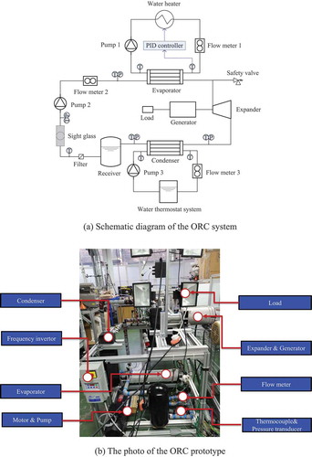
K-type thermocouples and pressure transducers, with accuracy of ±1% of the measured value, are installed at both the inlet and outlet of each component. A Hall Effect turbine flow-meter with an accuracy of ±0.75% of the measured value was installed at the outlet of the pump. At the front of the flow meter, a filter is used to filter out the impurities of the working fluid that flows into the flow meter clean. A power meter was connected with the loads to indicate the electric energy output, including the voltage, current and power. A Hall Effect turbine flow meter with accuracy of ±3% is used to measure the flow rate of the cooling water. All the main components and test equipment are listed in . The schematic diagram and photo of the experimental setup are shown in ()) and )) respectively.
Table 1. Specifications of main components and test equipment
In the ORC prototype, 1 kW oil-free semi-hermetic scroll expander is used to convert heat to power. Scroll expander belongs to volumetric expander, which is characterized by a built-in volume ratio. The expansion volume ratio is defined as the ratio of working fluid-specific volumes calculated from the measured temperature and pressure at the expander inlet and outlet (Lemort et al. Citation2009).
Wherein, the v, T, and P represent the specific volume, temperature, and pressure of the working fluid.
Correspondingly, the pressure ratio is defined as ratio of the measured pressure at the expander inlet to the measured pressure at the expander outlet.
The heat transferred in the Evaporator and Condenser can be calculated as the following:
Wherein, the Q, m, and h represent the heat capacity, mass flow rate and enthalpy, respectively.
The efficiency of the expander is defined as:
The measured efficiency of ORC can be defined as:
Wherein, the η and W represent the efficiency and power, respectively.
3. Operation conditions
To study the effects of mass flow rate of working fluid, the pressure ratio and the load over the performance of the ORC, the following tests were performed:
Test 1: The temperatures of the hot water (heat source) and cooling water (heat sink) are fixed to be 95°C and 19.8 °C, respectively. The mass flow rate of hot water and cooling water are kept constant during the test. The mass flow rate of the working fluid is adjusted by changing the frequency of the circulation pump from 10 to 30 Hz.
Test 2: The temperatures of the hot water and cooling water are fixed to be 95°C and 18.8 °C, respectively. Three resistance heaters are wired in parallel, acting as the load of the ORC system.
Test 3: The temperature of the hot water was kept at 94.5 °C. During the test, the mass flow rate of working fluid is fixed with the circulation pump running at 20 Hz. The condensation temperature was regulated by adjusting the mass flow rate of the cooling water.
4. Results and discussion
4.1. Effect of the mass flow rate and the load
A series of experiments have been performed to evaluate the system performance against a range of parameters, including the mass flow rate of working fluid, the mass flow rate of the cooling water and the load.
4.1.1. Test 1
In this test, the generated power by the expander-generator unit is consumed by several lamps, which are wired in parallel. Each lamp is controlled by a switch whether it is energized or not. The electric load resistance can be regulated through the switches.
shows the effect of circulation pump frequency on the mass flow rate of working fluid. From the curves, we can observe that the mass flow rate increases with the increasing pump frequency. In the test system, the circulation pump used is a positive displacement pump that uses a combination of the reciprocating action of rubber diaphragm and suitable valves on either side of the diaphragm to pump the fluid. As the pump frequency increases, the increasing reciprocating motion frequency leads to an increase in the mass flow rate proportionally. It allows for an accurate control of the superheat degree at the evaporator outlet.
Figure 2. Variation of mass flow rate with circulation pump frequency
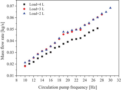
Furthermore, the mass flow rate is also affected by the load. In respect to the effect of load, when the load is switched from 2 lamps to 4 lamps, the back pressure of pump is found to be enhanced while the rotation speed of the expander becomes lower even with the same pump frequency. During this process, the leakage becomes greater, causing the flow rate becomes smaller with higher load (Lemort et al. Citation2009).However, the difference of the flow rate between 2 lamps and 3 lamps is minor. This may be due to the reason that the pressure difference of the back pressure of the pump (also the inlet pressure of the expander) is minor between 2 lamps and 3 lamps(shown in), which may be caused by unsteady heat source temperature and heat sink.
shows the variation of working fluid temperature and superheat at the expander inlet. Generally, the pressure inside the evaporator is closely relative to both the pump frequency and the load connected to the expander-generator unit. When the system is operated with a small flow rate, the pressure at the evaporator inlet is low and the temperature difference between the heat source and the working fluid after heat transfer is minor. As a result, the corresponding superheat degree is high. When the circulation pump frequency increases, the superheat degree shows an evident decreasing trend although the variation of the inlet temperature at the evaporator is minor. This is because the evaporation temperature increases with the pressure in the evaporator as the mass flow rate increases. The superheat degree becomes 0 when the pump is operated between 25 and 27 Hz. The superheat degree of 0 is found to appear earlier when it is running with higher load. After that, a dramatic decrease in the working fluid temperature appears if the flow rate keeps increasing further. This is because, for a certain heat exchanger, the heat transfer area is fixed. Although increasing the mass flow rate can enhance the heat exchange, the increased heat exchange is insufficient to support the evaporation of all the working fluid after the superheat degree becomes 0. With the further increase of the flow rate, the working fluid rapidly enters the liquid phase region from the two-phase region, leading to sharp decline in the working fluid temperature.
Figure 3. Variation of temperature and superheat degree at the expander inlet with circulation pump frequency
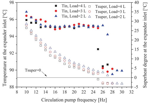
Furthermore, while the load is higher, the pressure increases sharply with the mass flow rate, as shown in (). And its corresponding saturation temperature also increases. The phenomenon of the working fluid entering into two phase region appears earlier when the ORC is operated with a heavier load when increasing the flow rate of working fluid.
Figure 4. Variation of the pressures at the expander inlet and outlet with mass flow rate
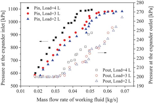
In ORC cycle, the pressures at the expander inlet and output represent the evaporation pressure and the condensation pressure and these two parameters affect the expansion process across the expander. () presents the variation of the inlet and outlet pressure of expander. It is evident that the inlet pressure increases dramatically by increasing the flow rate, and the system will run with a higher evaporation pressure for a higher load condition. This lie in the fact that for the same mass flow rate, the rotation speed of the expander becomes smaller and the pressure difference across the expander is enhanced while increasing the load from 2 lamps to 4 lamps. However, the inlet pressure keeps almost unchanged after the superheat becomes below 0 °C though the mass flow rate keeps increasing.
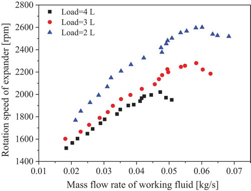
As it can be seen from (), as the flow rate of working fluid increases, the rotation speed of expander firstly increases, and then begin to decrease after a peak. The peak appears at the condition that corresponds to the superheat degree of 0. For a given mass flow rate, the expander rotates faster when the generator is operated with a lower load. The measured maximum rotation speed is over 2600 rpm when it is running with 2 lamps.
Figure 5. Variation of the expander rotation speed with mass flow rate
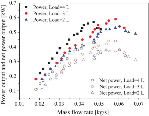
From (), we can find that the power output and the net power output show the same trend, both increasing first and then decreasing as the flow rate of ORC working fluid increases. Moreover, the peaks appear when the superheat degree at the expander inlet becomes 0. As the flow rate of working fluid increases, more heat is needed to be transferred from hot water to the working fluid in the evaporator. For the same heat source, as the mass flow rate of working fluid increases, the superheat degree of the vapor gradually decreases until 0. If the mass flow rate of working fluid increases further, the working fluid at the expander inlet will enter two phase region. As a result, the expander’s power output decreases. That’s why the peak net power output appears when the working fluid is not superheated. Therefore, in order to obtain a better system performance, the system should be controlled to maintain the least possible superheat degree at the expander inlet. The results also show that the power consumed by the pump ranges from 0.07 to 0.18 kW, which accounts 22 to 39% of the power output of expander-generator unit. The maximum power outputs of the expander-generator unit are 0.57, 0.59, and 0.54 kW, respectively, when their loads are 4 lamps, 3 lamps and 2 lamps in parallel, respectively. The corresponding maximum net power output is 0.43 kW, 0.44 kW and 0.38 kW, respectively.
Figure 6. Variation of the power output and net power output with the mass flow rate
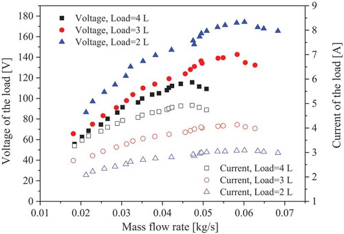
In the ORC system, the electrical energy generated by the expander-generator unit is consumed by the loads(lamps, heaters and so on). The output of the generator is measured in terms of voltage and the current, as shown in (). The tested result indicates that both voltage and current increase first and then decrease. The peak values of these curves are also found under the conditions with superheat degree of 0, which correspond to the maximum power output moment in (). A higher voltage can be achieved when the generator is connected with less lamps and the maximum voltage for 2 lamps is 174 V. However, its corresponding current is lower than that under the conditions with more lamps.
Figure 7. Voltage and current output from the generator under different loads
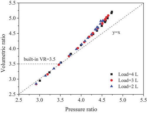
The positive displacement expander that has a fixed built-in volume ratio is commonly used in the small-scale ORC. In our test rig, a scroll expander with built-in volumetric ratio of 3.5 is used in this study. () shows the relationship between the pressure ratio and the volume ratio, and only the superheated conditions are studied in this part. Results in () indicate that the scatter is a bit deviated away from the y = x line when the pressure ratio higher than 3.75. It means that the pressure ratio is not exactly equal to the pressure ratio since the refrigerant is not an ideal gas. It is seen that the corresponding built-in pressure ratio is also about 3.5. However, the expander is normally running under the off-design condition at most of the time due to the fixed built-in volume ratio and the instability in the heat source conditions, variation of the mass flow rate and the loads. The mismatching between built-in and actual expansion ratio affects the expander efficiency greatly in the practical application, including the impact of under and over expansion on the ORC performance at off-design condition. It is recommended to be operated at the built-in volume ratio to obtain a better performance.
Figure 8. Variations of pressure ratio and the volumetric ratio with mass flow rate when it is superheated
The results above include both the superheated and the two-phased conditions. From the above analysis we can learn that the superheated working fluid is commended to obtain a better performance, although the scroll expander can handle the two phase expansion. Therefore, the following results only consider the superheated condition.
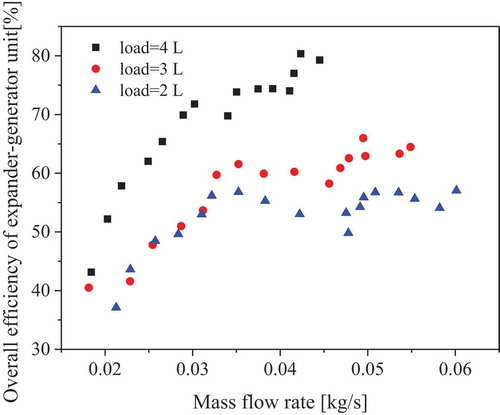
The overall efficiency of the expander-generator is defined as the measured power output to the heat energy difference between the expander inlet and outlet. It can be taken as the combination of the expander efficiency and the generator efficiency. The overall efficiencies with different loads have similar variation trend, all increasing first and then fluctuating with the increase of flow rate. When the system is running with 4 lamps as load, the overall efficiency of the expander-generator unit is the maximum under the same mass flow rate. This can be illustrated by the fact that the rotation speed of the expander increases as the mass flow rate is enhanced. As regarding to the expander, the isentropic efficiency will have a peak value around the built-in volumetric ratio, while the expander mechanical efficiency will increase at small flow rate and then become unchanged, according to Ref (Bao, Wang, and Roskilly Citation2014). The results also agree well with the research by Lemort, Declaye, and Quoilin (Citation2011): at low rotating speed, the relative impact of leakage on the performance is predominant. On the contrary, at higher speed, the predominant sources of inefficiency are the mechanical loss and the inlet pressure drop. The generator efficiency would have an optimum efficiency under its rated rotation speed of 3000 rpm. The combined effect of these two components, as well as the unstable heat source and heat sink, lead to the overall efficiency shown in (). Among all the tested conditions, the maximum overall efficiency for 4 lamps, 3 lamps and 2 lamps are 0.80, 0.66, and 0.57, respectively.
Figure 9. Overall efficiency of the expander-generator unit under superheated conditions
Thermal efficiency is a key index to evaluate an ORC system. It is defined as ratio of the electricity output to the measured heat input to the working fluid. During the test, all the operation parameters (the mass flow rate, the pressure and the temperature etc.) vary when the pump frequency is regulated. As shown in (), the thermal efficiency increases with the raise of pressure ratio when the load is 3 lamps and 4 lamps, which can be illustrated by the fact that the power output increases with the mass flow rate (in ). The maximum thermal efficiency among all the considered conditions is 4.09%.
Figure 10. Thermal efficiency of the ORC under different pressure ratios with different loads
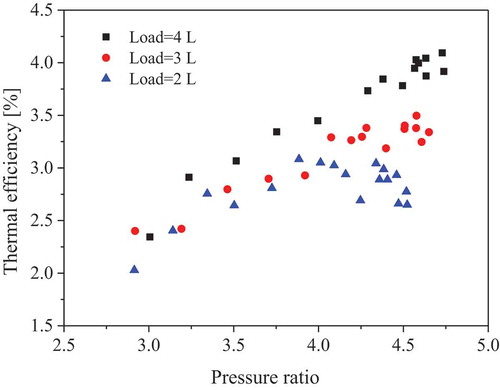
However, when the load is 2 lamps, the thermal efficiency decreases when the pressure ratio is higher than 4 and a peak efficiency occurs. As mentioned above, when the ORC is operated with a higher load, the mechanical loss accounts for only a small part of the converted energy for its low rotation speed. While load is reduced, the proportion of the mechanical loss accounts for a big part due to the high rotation speed of the expander. For the idle condition, the friction will consume all the power generated by the expander and there is no power output. From this perspective of system efficiency, this ORC system is recommended to operate under the medium high load conditions. According Lemort’s study (Citation2011), the value of the pressure ratio that maximizes the isentropic efficiency is not constant for all rotation speeds. That can explain why a peak value appears when the pressure ratio is 4 for 2 lamp condition, while 3 and 4 lamps conditions do not appear yet during the test.
4.1.2. Test 2
Based on the aforementioned results, it is concluded that the ORC performs better when the ORC is operated with a higher load. Consequently, the lamps has been replaced by 3 heaters of 750 W in parallel for consideration. The heat source temperature is 95 °C, and the cooling water temperature is 18.7 °C. During this test, the mass flow rate of working fluid is controlled by adjusting the pump frequency, from 10 to 27 Hz.
() indicates the power and net power output when the generator is connected with 3 heaters of 750 W in parallel. It can be seen that the variation trend is similar to that shown in (), increasing first and then decreasing with the raise of flow rate. The peak values of power output and net power output are 0.61 and 0.46 kW, respectively, when the mass flow rate is 0.055 kg/s. We also notice that the gap between the power output and net power output, namely the work consumed by the pump, increases with the mass flow rate of working fluid owning to the grown load.
Figure 11. Variation of power output and net power output
() and () present the influence of the pressure ratio on the performance of the expander-generator unit and the ORC system, respectively. The results indicate that the pressure ratio ranges between 3 and 5.25 when the pump frequency is regulated from 10 to 27 Hz. Both the overall efficiency of the expander-generator unit and thermal efficiency increase with the raise of pressure ratio. Ideally, the maximum expander efficiency would occur at the built-in pressure ratio. However, due to the pressure drop, friction, and irreversibility of flow inside the expander, the optimum performance can be achieved when its practical pressure ratio is higher than the built-in pressure ratio.
Figure 12. Effect of pressure ratio on the overall efficiency of expander-generator unit
Figure 13. Effect of the pressure ratio on the thermal efficiency
4.2. Test 3
An experimental test was performed to study the effect of condensation temperature on the ORC performance in this part. It is well known that the condensation temperature can be regulated by changing either the inlet temperature or the flow rate of the cooling water. During this test, the condensation temperature was regulated by adjusting the flow rate of the cooling water.
() shows the effect of condensation temperature on the net power output and thermal efficiency. The condensation temperature ranges from 284 K to 311 K. It is evident that both the net power output and the thermal efficiency decline when the condensation temperature increases. As the condensation temperature is enhanced, the enthalpy difference between the expander inlet and outlet becomes smaller, the heat absorbs by working fluid per unit becomes less during the evaporation process although the power output also decreases. In that case, the outlet temperature of the exhaust gas becomes higher and less energy will be recycled by the ORC. In general, a low condensation temperature is preferred for the ORC power generation cycle.
Figure 14. Effect of condensation temperature on the net power output and thermal efficiency
shows the variation of the pressure ratio and the overall efficiency of the expander-generator unit with different condensation temperatures. In this test, the flow rate of working fluid is kept unchanged, and the heat source (hot water) supplied to the evaporator remains the same. Therefore, as the mass flow rate of the heat sink (cooling water) declines, the condensation temperature is enhanced. In that case, both the pressure at the expander inlet and outlet increase while the growth of the outlet pressure is greater, leading to a lower pressure ratio. Therefore, the overall efficiency of the expander decreases as well.
Figure 15. Effect of condensation temperature on the overall efficiency of the expander-generator unit and pressure ratio
5. Conclusion
In this paper, a lab-scale ORC prototype has been designed, constructed and tested. The system aims to explore the potential in recovering the low-temperature heat contained in the jacket water of internal combustion engine. The performance of ORC system has been evaluated under different working conditions to study the effect of flow rate of working fluid, load and condensation temperature. The conclusions are given as following.
The best performance of ORC can be obtained when the system is operated with superheat degree of 0.
The maximum power output and net power output are 0.61 and 0.46 kW, respectively, and the corresponding thermal efficiency is about 3.5% when the heat source temperature is about 95 °C.
The maximum overall efficiency of the expander-generator unit can be reached with a pressure ratio higher than the built-in pressure ratio due to the pressure loss and heat loss issue in practical application.
Acknowledgments
This research was funded by Engineering and Physical Sciences Research Council (EP/N020472/1, EP/N005228/1, EP/R003122/1, and EP/P028829/1) in the United Kingdom, also supported by the Fundamental Research Funds for the Central Universities, SCUT (2020ZYGXZR027) and MOE Key Laboratory of Enhanced Heat Transfer and Energy Conservation, Beijing University of Technology in China. We gratefully acknowledge the assistance of PhD student Andrew Mckeown and engineer Peter Miller in the experiment. No potential competing interest was reported by the authors.
Additional information
Funding
References
- Abadi, G. B.,E. Yun, and K. C. Kim.2015.Experimental study of a 1 kw organic rankine cycle with a zeotropic mixture of R245fa/R134a.Energy 93:2363–73. doi:10.1016/j.energy.2015.10.092.
- Bao, H.,Y. Wang,andA. P. Roskilly.2014.Modelling of a chemisorption refrigeration and power cogeneration system. Applied Energy 119 (12):351–62. doi:10.1016/j.apenergy.2014.01.012.
- Bao, J.,andL. Zhao.2013.A review of working fluid and expander selections for organic Rankine cycle. Renewable and Sustainable Energy Reviews24:325–42.doi:10.1016/j.rser.2013.03.040.
- Dai, X., L. Shi,Q. An,andW. Qian. 2016. Screening of hydrocarbons as supercritical ORCs working fluids by thermal stability.Energy Conversion and Management 126:632–37.doi:10.1016/j.enconman.2016.08.024.
- Declaye, S., Quoilin, S., Guillaume, L., and Lemort.,V.2013.Experimental study on an open-drive scroll expander integrated into an ORC (Organic Rankine Cycle) system with R245fa as working fluid. Energy 55:173–83. doi:10.1016/j.energy.2013.04.003.
- Desideri, A., S. Gusev,M. van den Broek,V. Lemort,andS. Quoilin.2016.Experimental comparison of organic fluids for low temperature ORC (organic Rankine cycle) systems for waste heat recovery applications.Energy97:460–69. doi:10.1016/j.energy.2015.12.012.
- Drescher, U., and D. Brüggemann. 2007. Fluid selection for the organic rankine cycle (ORC) in biomass power and heat plants. Applied Thermal Engineering 27 (1):223–28. doi:10.1016/j.applthermaleng.2006.04.024.
- Farrokhi, M., S. H. Noie, and A. A. Akbarzadeh. 2014. Preliminary experimental investigation of a natural gas-fired ORC-based micro-CHP system for residential buildings. Applied Thermal Engineering 69 (1–2):221–29. doi:10.1016/j.applthermaleng.2013.11.060.
- Hatami, M., D. D. Ganji, and M. Gorji-Bandpy. 2014. A review of different heat exchangers designs for increasing the diesel exhaust waste heat recovery. Renewable and Sustainable Energy Reviews 37:168–81. doi:10.1016/j.rser.2014.05.004.
- Hsu, S. W., H. W. Chiang, and C. W. Yen. 2014. Experimental investigation of the performance of a hermetic screw-expander organic Rankine cycle. Energies 7 (9):6172–85. doi:10.3390/en7096172.
- Jiang, L., H. T. Lu, L. W. Wang, P. Gao, F. Q. Zhu, R. Z. Wang, and A. P. Roskilly. 2017. Investigation on a small-scale pumpless Organic Rankine Cycle (ORC) system driven by the low temperature heat source. Applied Energy 195:478–86. doi:10.1016/j.apenergy.2017.03.082.
- Kang, S. H. 2012. Design and experimental study of ORC (organic Rankine cycle) and radial turbine using R245fa working fluid. Energy 41 (1):514–24. doi:10.1016/j.energy.2012.02.035.
- Lecompte, S., H. Huisseune, M. van den Broek, B. Vanslambrouck, and M. De Paepe. 2015. Review of organic rankine cycle (ORC) architectures for waste heat recovery. Renewable and Sustainable Energy Reviews 47:448–61. doi:10.1016/j.rser.2015.03.089.
- Lemort, V., C. Declaye, and S. Quoilin. 2011. Experiment characterization of a hermetic scroll expander foor use in a micro-scale Rankine cycle. Proceeding of the Institution of Mechanical Engineers. Part A: Journal of Power and Energy 226 (1):126–136.
- Lemort, V., S. Quoilin, C. Cuevas, and J. Lebrun. 2009. Testing and modeling a scroll expander integrated into an Organic Rankine Cycle. Applied Thermal Engineering 29 (14–15):3094–102. doi:10.1016/j.applthermaleng.2009.04.013.
- Li, M., J. Wang, S. Li, and Y. Dai. 2015. Experimental study and numerical simulation of a regenerative ORC utilizing low-grade heat source. Journal of Energy Engineering 04014011.
- Liang, Y., G. Shu, H. Tian, H. Wei, X. Liang, L. Liu, and X. Wang. 2014. Theoretical analysis of a novel electricity–cooling cogeneration system (ECCS) based on cascade use of waste heat of marine engine. Energy Conversion and Management 85:888–94. doi:10.1016/j.enconman.2013.12.070.
- Liang, Y., G. Shu, H. Tian, and Z. Sun. 2018. Investigation of a cascade waste heat recovery system based on coupling of steam Rankine cycle and NH3-H2O absorption refrigeration cycle. Energy Conversion and Management 166:697–703. doi:10.1016/j.enconman.2018.04.064.
- Liang, Y., X. Bian, W. Qian, M. Pan, Z. Ban, and Z. Yu. 2019. Theoretical analysis of a regenerative supercritical carbon dioxide Brayton cycle/organic Rankine cycle dual loop for waste heat recovery of a diesel/natural gas dual-fuel engine. Energy Conversion and Management 197: 111845.1–111845.12.
- Liang, Y., Z. Sun, M. Dong, J. Lu, and Z. Yu. 2020. Investigation of a refrigeration system based on combined supercritical CO2 power and transcritical CO2 refrigeration cycles by waste heat recovery of engine. International Journal of Refrigeration 118:470–82. doi:10.1016/j.ijrefrig.2020.04.031.
- Liang, Y., and Z. Yu. 2019. Working fluid selection for a combined system based on coupling of organic Rankine cycle and air source heat pump cycle. Energy Procedia 158:1485–90. doi:10.1016/j.egypro.2019.01.354.
- Ling, H. Y., H. T. Chen, W. Shuang, L. J. Ren, L. B. Xi, W. P. Zhang, F. Y. Qiang, and W. Qian. 2017. Operation characteristic and performance comparison of organic Rankine cycle (ORC) for low-grade waste heat using R245fa, R123 and their mixtures. Energy Conversion and Management 144:153–63. doi:10.1016/j.enconman.2017.04.048.
- Muhammad, U., M. Imran, D. H. Lee, and B. S. Park. 2015. Design and experimental investigation of a 1kW organic Rankine cycle system using R245fa as working fluid for low-grade waste heat recovery from steam. Energy Conversion and Management 103:1089–100. doi:10.1016/j.enconman.2015.07.045.
- Pang, K. C., S. C. Chen, T. C. Hung, Y. Q. Feng, S. C. Yang, K. W. Wong, and J. R. Lin. 2017. Experimental study on organic rankine cycle utilizing R245fa, R123 and their mixtures to investigate the maximum power generation from low-grade heat. Energy 133:636–51. doi:10.1016/j.energy.2017.05.128.
- Qiu, G., Y. Shao, J. Li, H. Liu, and S. B. Riffat. 2011. Experimental investigation of a biomass-fired ORC-based micro-CHP for domestic applications. Fuel 90 (1):374–82.
- Shu, G., Y. Liang, H. Wei, H. Tian, H. J. Zhao, and L. Liu. 2013. A review of waste heat recovery on two-stroke IC engine aboard ships. Renewable and Sustainable Energy Reviews 19:385–401. doi:10.1016/j.rser.2012.11.034.
- Unamba, C. K., P. Sapin, X. Li, J. Song, K. Wang, G. Shu, H. Tian, and C. N. Markides. 2019. Operational optimisation of a Non-recuperative 1-kWe Organic Rankine cycle engine prototype. Applied Sciences 9 (15):3024. doi:10.3390/app9153024.
- Yang, S. C., T. C. Hung, Y. Q. Feng, C. J. Wu, K. W. Wong, and K. C. Huang. 2016. Experimental investigation on a 3 kW organic Rankine cycle for low-grade waste heat under different operation parameters. Applied Thermal Engineering 113:756–64. doi:10.1016/j.applthermaleng.2016.11.032.
