
 ?Mathematical formulae have been encoded as MathML and are displayed in this HTML version using MathJax in order to improve their display. Uncheck the box to turn MathJax off. This feature requires Javascript. Click on a formula to zoom.
ABSTRACT
Hairiness is a key index for yarn quality as it has a critically negative influence on weaving process. Yarns with less hairiness are highly demanded in textile industry. This work introduced an innovative way to mainly reduce the hairiness of ring spun yarns. Rotary compact groove cylinders (CGC) have been installed in the front of spinning nip to minimize the spinning triangle. Theoretical analysis has been carried out to reveal the mechanics of reducing hairiness. Two yarn types spun using conventional ring spinning and Siro spinning both with CGC device have also been compared to investigate this spinning method on the general application of different yarn types. Experimental results indicate that the CGC device can capture and control float fibers in the spinning triangle, pure cotton, and flax/cotton blend yarn were both improved with less hairiness (with reduction ratio of 3 mm hairs at 40% and 38%, respectively). The strength of CGC pure cotton yarn was improved, while the unevenness of CGC flax/cotton blend yarn were slightly deteriorated compared with original yarn. This method is easy to realize and requires no extra energy, which has great potential to be applied in the industrial production of ring spun yarns with better properties.
摘要
毛羽是纱线质量的一个关键指标,因为它对织造过程有严重的负面影响. 纺织工业对毛羽少的纱线的需求很大. 这项工作介绍了一种主要减少环锭纺纱毛羽的创新方法. 旋转紧凑型槽筒(CGC)已安装在纺纱辊隙的前部,以最小化纺纱三角. 已经进行了理论分析以揭示减少毛羽的机理. 还比较了使用常规环锭纺纱和使用CGC装置的西罗纺纱的两种纱线类型,以研究这种纺纱方法在不同纱线类型的一般应用. 实验结果表明,CGC装置可以捕获和控制纺纱三角区中的漂浮纤维,纯棉和亚麻/棉混纺纱都得到了改善,毛羽更少(毛羽减少率分别为40%和38%). 与原纱相比,CGC纯棉纱的强度有所提高,而CGC亚麻/棉混纺纱的不匀度略有恶化. 该方法易于实现,不需要额外的能量,在工业生产性能更好的环锭纺纱中具有很大的应用潜力.
Introduction
In the spinning industry, yarn quality is significantly influenced by the hairiness and other factors (Haleem and Wang Citation2015; Zhang and Xin Citation2016; Çukul and Beceren Citation2016). A main reason is that hairiness longer than 3 mm lead to the fiber entanglement between yarns in the shed, negatively affecting weft motion in weaving process, causing defects on fabric and deteriorate fabric handle. Reducing yarn hairiness is important to large-scale production of high-quality yarns and fabrics. Several methods have been invented to achieve this goal and there existing three main spinning technologies for decreasing hairiness at the industrial production stage, including compact spinning (Mei et al. Citation2021; Saty, Akankwasa, and Wang Citation2021; Uddin, Afroz, and Jalil Citation2015; Vadood, Kheirkhah Barzoki, and Safar Johari Citation2017), Siro spinning (Khan, Begum, and Sheikh Citation2019; Kumar et al. Citation2020; Liu et al. Citation2015), and Solo spinning (Babaeipour, Ghane, and Hasani Citation2022; Lamb and Wang Citation2010). Compact spinning includes pneumatic and mechanic (Rocos) compact spinning, their principles are both to narrow fiber strands after drafting by the front rollers, aiming to diminish or eliminate spinning triangle area. Unlike pneumatic compact spinning using negative pressure airflow, mechanic compact spinning applies magnet compact device to condense and control fiber strand (Liu, Zhang, and Su Citation2016). In contrast, Siro spinning method initiatively pre-twists two sub-strands drafted from two slivers, so that two smaller spinning triangles can control float fibers better. During the ply-twisting, hairs outside the pre-twisted strands are wrapped into yarn stem (Han et al. Citation2015). In this way, Siro spinning can also reduce hairiness. Similarly, Solo spinning exert pre-twists on multiple fiber strands after splitting one single strand using a pair of slotted solo-spun rollers. After ply-twisting, the multiple strands are integrated into the single ply-twisted inner structure that can lock hairs (Chang, Tang, and Wang Citation2003).
However, some disadvantages for these technical methods may limit their more general application in the industrial production. Besides the high cost of installation and operation compared with conventional ring spinning, tremendous energy consuming rooted in the supply of negative pressure airflow discourage ordinary spinning mills from using pneumatic compacting spinning (Li, Xie, and Liu Citation2017). Mechanic compact spinning cause thickness, affecting the unevenness of yarns (Altas and Kadoğlu Citation2012). At the same time, these two compact spinning methods can only perform well on high and low count yarns, respectively. Solo spinning has restricted requirement for the amount, length and strength of raw materials to ensure the successful twisting of each fiber strand. Both Solo and Siro spinning are applied into yarns with higher counts, while the performance on hairiness reduction of Siro spinning is limited (Pourahmad and Johari Citation2011).
Considering these problems listed above, many researchers have dedicated into energy-saving, low-price, easy-implemented spinning methods to improve yarn qualities. Contact surface in the yarn formation section (between front roller nip and spinning guider) has been proved to reduce hairiness effectively (Xia et al. Citation2012). Unfortunately, this method causes the deterioration of yarn irregularity and strength. Another delicate design solves this problem using a rotary grooved cylinder that is deployed under the yarn formation channel rather than a static grooved cylinder exerting great friction on the yarn stem (Yu et al. Citation2018). Although the reduction of hairiness has been reported to be effective, the±50% neps increases.
In this work, an innovative method to reduce hairiness of ring spun yarns is introduced, by simply installing a rotary CGC device in the front nip. The mechanical model has been built to analyze the process of hairiness reduction, while the experimental results of designed devices will be used to verify the theoretical method. In details, the designed CGC device has been compared in terms of performance on the hairiness reduction as well as other yarn properties.
Theoretical discussion
Spinning triangle area reformation and principle of condensing fiber strand
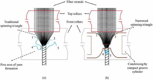
In the traditional ring spinning, a fiber strand (flat structure) is twisted to a yarn stem (spatial structure). As this structure transformation, a small triangle area forms after leaving the front nip line (). The ends of fibers are forced to transfer from center to edge or edge to center perpetually and move forward several times, until being twisted to be a yarn (Shao et al. Citation2019). As a result, fibers are arranged spirally in the yarn stem. Yarn hairiness is generally recognized as the hairs protruding from yarn body. There may be three main cases for hairiness production in ring spinning way during yarn formation. The first one is that floating fibers in the edge of spinning triangle cannot be gripped by the twisting force, leading the fiber end exposed out of the yarn body. During the fiber transferring progress, fiber ends are forced to move out of yarn body, forming hairiness. Even if the tip of fiber is controlled by twisting force, the end of fiber protrudes out yarn stem due to the stiffness, forming harmful hairiness. Reducing the size of spinning triangle or increasing the control force on fibers can be effective to produce higher quality yarns with less hairiness (Wang, Huang, and Huang Citation1999). Based on this analysis, a significant modification can be conducted (). The spinning triangle has been reformed, becoming longer and narrower at the spinning point. A fiber strand is forced to be condensed once delivered from the front nip line, by the CGC device. The dynamic equilibrium of fiber strand width on the front bottom roller is broken, forming the narrow spinning triangle to the twisting point under the forced control. As a result, the in-out transferring of fibers can be facilitated to enhance the cohesion between fibers. At the same time, the floated fibers are controlled under the tridimensional friction field in this device and twisted into yarn stem, while hairs protruded outside of yarn are captured and wrapped onto yarn stem. In this way, yarn becomes more compact, and hairiness are reduced effectively.
Figure 1. Spinning triangle (a) without and (b) with CGC device.
Mathematic modeling of gathering and transferring fibers
A typical traditional spinning triangle is ideally considered to be symmetric (). Fibers are assumed to distribute evenly and equally between two sides of the middle point of the front nip line, O. P is the twisting point, forming the spinning triangle area with two edge points A and B, with the spinning tension F. The width and height of spinning triangle are denoted with W and H, respectively. is the angles between the right
th fiber and the central fiber, correspondingly. While
is the initial mean length of fiber,
is the elongation ratio of
th fiber caused by tension.
Figure 2. Symmetric and asymmetric spinning triangles: (a) ideal symmetric case (b) asymmetric case with vertical spinning tension (c) asymmetric case with offset spinning tension (d) asymmetric case with the effect of groove cylinder.
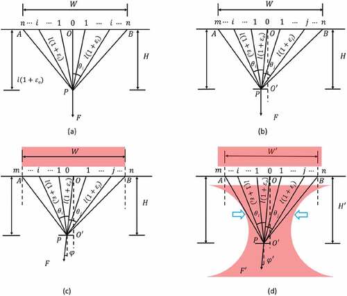
In the practical production, the spinning triangle is supposed to be the cases shown in . The numbers of fibers distributed between each side of O point are different, which is determined by the distribution of fiber tension. With the combined effect of friction between bottom roller and fiber strand, the twisting point is offset from the central axis (OO’) of spinning triangle. However, there also exists an offset spinning tension F in the practical twisting process shown in , which causes the angle and affect the tension of each fiber in the spinning triangle. After the introduction of a rotary CGC device, the mechanical model has been changed (). The tripartite agglomeration effect of groove cylinder is imposed on the fibers to contribute to a narrower and longer spinning triangle after fiber strand leaves front nip, improving yarn properties.
As fibers in spinning triangle are subjected to small strain, it is assumed that the stress-strain behavior of single fiber follows the Hookean law. The tension of single fiber can be calculated using the following equation:
Where A denotes the fiber linear density, E is the Young’s modulus of fibers (corresponding to fiber linear density), and
are the strain of the left
th and right
th fiber, respectively.
Regarding the triangle OPO’ in , the following equation of incline angle for spinning tension can be obtained:
Analyzing EquationEquations (1)(1)
(1) (Equation2
(2)
(2) )(Equation3
(3)
(3) ), the tension of single fiber in the spinning triangle can be expressed as:
In the practical spinning, is dynamic and small comparing with
and
. According to the change range of incline angles (
and
),
ranges above zero, meaning that
are monotone increasing functions in respect to the incline angles.
is below zero only when
is smaller than
. In most cases,
is greater than zero, indicating that
will decrease slightly in a short range and increase dramatically in most range as the increase of incline angle. This theoretical analysis above demonstrates that the single fiber tension increases exponentially from the center to the side of spinning triangle (except few of fibers in the center). Too strong tension of fiber in the edge of spinning triangle not only causes breakage of fibers, increasing hairiness, but also has resistant effect on the torque, influencing the twisting process negatively. Compared with traditional spinning triangle, narrower and longer spinning triangle created by the grooved cylinder has a narrower range of incline angles, meaning that the tension of edge fibers is smaller and the distribution of all fibers are more even. Both the smaller fiber tension and narrower spinning triangle give rise to the effective twist propagation to single fibers. In this way, more control force on these fibers will mitigate fiber protrusion and reduce the hairiness.
Experimental details
Sample and device preparation
Pure cotton rovings and twin flax/cotton rovings were prepared to spin yarns, typicallly reflecting the effect of hairiness reduction with CGC device for one component yarns and blend yarns. These two types of rovings were sourced from Anhui Huamao Group Co, Ltd and Hubei Jinghua Textile Group Co, Ltd, respectively. The roving samples were randomly selected from the spinning mills, being made under the same conditions, from the same batch of raw fibers. Cotton yarns were produced using the same cotton rovings during the entire experimental, and the same flax/cotton rovings were used to spin flax/cotton yarns.
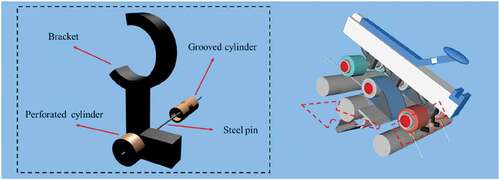
The experimental devices used were novel and designed to fit the spinning machines. A typical design is shown in . This novel device comprised of four components, the bracket helped to connect the grooved cylinder to the spinner, with the position is below the front nip line (between front rollers), while the perforated cylinder ensured the grooved cylinder located to the knurling surface of the front bottom roller.
Figure 3. The schematic diagram of designed device for experiment.
Methodology
To validate the theoretical analysis of property variations for ring spun yarn with and without CGC device, the designed apparatus was installed just under the front top rollers of a ring spinning frame in the standard workshop of Anhui Huamao Group mill (). The similar experiment was also conducted on the different type of ring spinning frame in the mill of Hubei Jinghua Textile Co, Ltd () to investigate the general effect of hairiness reduction on different yarn types (pure cotton yarn in Huamao and flax/cotton blend yarn in Jinghua). The details of experimental settings are listed in .
Figure 4. (A) schematic diagram for spinning with CGC device; installation of CGC device for (b) pure cotton yarn and (c) flax/cotton blend yarn.
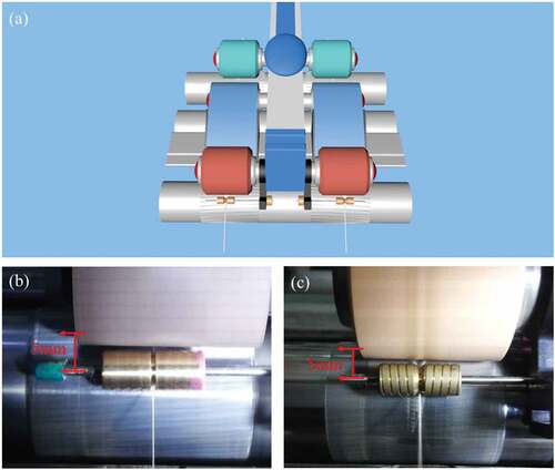
Table 1. Practical experimental settings for cotton and flax/cotton yarn.
According to , the distance between the front nip line and the center of a grooved cylinder was approximately 5 mm, which was determined by the length of connecting bracket. The design diameter and groove of cylinder resulted in around 6 mm contacting length between the spinning strand and the groove surface. Using these experimental settings listed above, spinning with and without CGC device were conducted for ring spinning and siro-spinning on six consecutive spindles, respectively. Although siro-spinning is importantly different in the technological parameter settings with conventional ring spinning, the designed device can be easily to apply on the spinning frame to optimize yarn properties, reflecting the generalization function of grooved cylinder.
As for test procedures, all the spun yarn samples were conditioned in the standard conditioned laboratory (temperature at 20 ± 2°C and relative humidity at 65 ± 2%) for at least 24 hours. They were then tested for yarn hairiness, tenacity property and yarn unevenness in order according to the standards ASTM D5647–07, ASTM D2256 M–21 and ASTM D1425 M–14. Yarn hairiness was conducted using a YG172A hairiness meter that counted the number of hairs protruded yarn with varied lengths. The segment length for each test was set to 10 m, while the test speed was set at 30 m/min. Each sample was tested for 50 m and the average of the result was figured out after six bobbin yarns was tested. A YG029 single yarn tensile strength tester was deployed to measure the tenacity of the yarns. All yarn samples were tested 10 times for each, with the gauge length for testing at 0.5 m and pretension at 0.5 cN/tex. As for yarn unevenness, the USTER4-SX capacitive unevenness tester was applied to test six bobbin yarns, with test speed at 400 m/min for one minute. Each sample was tested for only once.
Independent Samples Test method for means comparison of two independent groups was conducted using the SPSS program to analyze the experimental results statistically, and the significance level was set at 0.05.
Results and discussions
The influence on the hairiness of yarn spun with and without CGC device
According to the results of , there is an exponentially decreasing trend for yarn hairiness as hair length increased, corresponding to the previous research (Viswanathan et al. Citation1988). A significant difference (the gaps in column diagram) can be found in the yarn hairiness of both yarn types spun with (CGC yarn) and without (original yarn) CGC device at the same level of hairiness length, and CGC yarn had much less hairiness than original yarn. These data reflected from the line chart confirm the result above, with the reduction of 3 mm hairs at approximately 40% and 38% for pure cotton and flax/cotton blend yarn, respectively. The number of other hairs with different length were also lower for CGC yarns, while the reduction ratios varied from around 20% to 60%. These findings indicated that CGC device exerted mechanical force on spinning triangle area to narrow fiber strands, facilitating in-out movement of fibers in the yarn stem. During this period, not only fiber ends were more easily to be wrapped with each other, but also floating fibers in the edge of spinning triangle area could be captured and twisted into yarn body. In this case, fiber ends were less likely to protrude out of yarn. In addition, 3D control force provided by the groove bent and rubbed hairs, making them to be re-trapped around yarn stem under twisting force. As a result, yarn hairiness was significantly reduced. The dramatic reduction of hairiness contributed to a smooth surface of yarn, shown in . Comparing , hairs were obviously wrapped or twisted on or in the yarn body, which enhance the validation for the theoretical analysis discussed above. Siro-spun yarn was supposed to be smoother than conventional ring spun yarn, while the amount of hairiness was higher for original flax/cotton blend yarn spun with siro-spinning (), which is corresponding to the results indicated by . The reason was that high rigidity and short length of flax fibers was responsible for the less spinnability, fiber ends were not easily to be twisted into yarn body. Even if CGC device could reduce hairiness effectively, flax/cotton blend yarn had more hairiness than pure cotton yarn (both improved by this device).
Figure 5. Comparison of yarn hairiness of original ring spun yarn and CGC yarn for (a) pure cotton yarn and (b) flax/cotton blend yarn; (c) images of hairiness for cotton yarn spun (i) without and (ii) with CGC device and for flax/cotton blend yarn (iii) without and (iv) with CGC device.
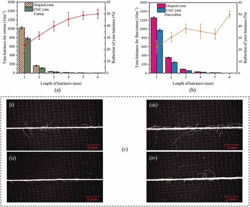
Comparing the hairiness of pure cotton and flax/cotton blend yarn, the reduction of yarn hairiness for them were close at about 40%, even if the amounts of hairiness of these two yarns were different. This may reflect that the function of hairiness reduction of CGC device was generally effective to different yarns, especially yarns spun with short fibers. The reason might be that short fibers were relatively less cohesive and easy to be influenced by the external factors in the spinning triangle area. There was a similar trend for these two yarns spun with CGC device that the average reduction ratios of hairiness longer than 3 mm were higher than the figure for hairiness with shorter length. The length and amount of yarn hairiness might be main two factors to lead to this trend. Longer hairs were imposed to a stronger frictional force as they contacted larger areas of the groove surface. In addition, they were relatively soft and easily bent. This combined effect contributed to the hair re-trapping, leading to higher hairiness reduction for hairs longer than 3 mm. The number of shorter hairs (1–2 mm) was significantly more than longer hairs, meaning that a certain percentage of short hairs superpose other fibers. These superposed fibers had less opportunities to contact CGC device and still protruded out of yarn body.
Difference in the unevenness between yarns spun with and without CGC device
The comparative results of unevenness between original and CGC yarns are shown in . According to the results extracted from , higher unevenness was produced for flax/cotton blend yarn. Since flax fibers were short and rigid, twisting force exerted limited regulation on the bending and in-out moving of fibers in the yarn body, causing irregular distribution of fibers along with fiber length. The unevenness of flax fiber itself contributed to the yarn unevenness, while the difference in the linear density between flax and cotton also led to unbalanced distribution of two components in yarn cross-section. Different unevenness was responsible for different+200% neps displayed in .
Figure 6. Unevenness of (a) pure cotton yarn and (b) flax/cotton blend yarn spun with and without CGC device; Neps+200% of pure cotton yarn and flax/cotton blend yarn spun with and without CGC device.
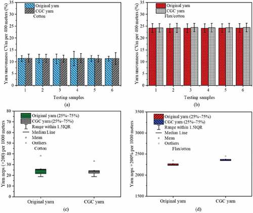
There was also a different trend in the comparison on yarn unevenness between original and CGC yarn for pure cotton and flax/cotton blend yarn types. The statistical analysis (Mann-Whitney test) indicated that the unevenness of CGC cotton yarn was similar to original cotton yarn (P > .05), whilst CGC flax/cotton blend yarn had a relatively higher unevenness (0.18) than original blend yarn (P < .05). This can be explained that a considerable proportion of hairs were wrapped around yarn body during hairiness reduction with CGC device, these re-trapped hairs may change the evenness of yarn. This change was reflected on flax/cotton yarn with more numbers of hairs reduced (wrapped on the surface of yarn). The different comparative results for yarn neps (+200%) in should be one of the main reasons for the significantly different unevenness between original and CGC flax/cotton blend yarn (not for pure cotton yarn). More details for the comparative study on the thin (−50%) and thick (+50%) places are listed in , and statistical results reflected that a significant difference could be found in the thin and thick places between flax/cotton blend yarns spun with and without CGC device, confirming the discussion above.
Table 2. Thin and thick places of yarns spun with and without CGC device.
Comparison between yarns spun with and without CGC device on the tensile properties
For cotton yarn, the breaking force (shown in ) was significantly (P < .05) improved by CGC device, with the mean increasing from 219.7 to 227.2 (3.4%). CGC device narrowed spinning triangle area, regulating fibers movement in the yarn stem. Fibers became more cohesive and yarn strength increased. In addition, the hairs re-wrapped in and on yarn body also contributed to higher breaking force. The elongation was not changed for yarns spun with and without CGC device. In contrast, there was no difference in both breaking force and elongation between original and CGC yarn spun with twin flax/cotton rovings (). Even if the flax/cotton fiber strand were narrowed in the spinning triangle area, the shape and surface incompatibility of these two fibers had negative influence on the cohesion between fibers in yarn stem. Rigidus flax fiber also impact the cohesive structure of yarn adversely. As a result, the breaking force was not improved. Similar to pure cotton yarn, the elongation of original flax/cotton blend yarn was the same to CGC yarn.
Table 3. Details of tensile properties for yarns spun with and without CGC device.
Conclusion
The theoretical model of applied force on fibers in the spinning triangle has been built to investigate the relationship between spinning triangle and yarn qualities. According to the study on mechanism of yarn formation, an innovative principle was developed to explore the method improving qualities. The corresponding device was also designed to verify the principle.
Experimental results indicated that the CGC device could regulate fibers in the spinning triangle area and produce higher quality of yarns, with hairiness reduction at approximately 40% for both pure cotton yarn and flax/cotton blend yarn. The breaking force of cotton yarn were improved by 3.4%, while no change was found for flax/cotton blend yarn. CGC device had no influence on the unevenness of cotton yarn, however, affecting the unevenness of flax/blend yarn negatively.
Highlights for this submission
Yarn qualities were improved without energy consumption using CGC device.
Mechanic analysis for single fibers.
Different yarns were compared to investigate the effect of CGC device on hairiness reduction.
CGC can be easily installed to reduce hairiness of yarns in conventional ring spinning and siro spinning
Acknowledgements
The authors wish to acknowledge Junlong Ni, Shengya Hu, Wei Ye, Chuang Ding and Renfa Jin for their great assistance with cotton and flax sampling for this work. The authors are also grateful to Spinning group in the State Key Laboratory of New Textile Materials and Advanced Processing Technologies at Wuhan Textile University (Weiqi Guo and Duo Xu) for technical support.
Disclosure statement
No potential conflict of interest was reported by the authors.
Additional information
Funding
References
- Altas, S., and H. Kadoğlu. 2012. Comparison of conventional ring, mechanical compact and pneumatic compact yarn spinning systems. Journal of Engineered Fibers and Fabrics 7 (1):87–12. doi:10.1177/155892501200700201.
- Babaeipour, A., M. Ghane, and H. Hasani. 2022. Comparison of solo and conventional ring yarns: Effects on the compression characteristics of cut-pile carpets. The Journal of the Textile Institute 1–7. doi:10.1080/00405000.2022.2050023.
- Chang, L., Z. Tang, and X. Wang. 2003. Effect of yarn hairiness on energy consumption in rotating a ring-spun yarn package. Textile Research Journal 73 (11):949–54. doi:10.1177/004051750307301103.
- Çukul, D., and Y. Beceren. 2016. Yarn hairiness and the effect of surface characteristics of the ring traveller. Textile Research Journal 86 (15):1668–74. doi:10.1177/0040517515596968.
- Haleem, N., and X. Wang. 2015. Recent research and developments on yarn hairiness. Textile Research Journal 85 (2):211–24. doi:10.1177/0040517514538692.
- Han, C., M. Wei, W. Xue, and L. Cheng. 2015. Numerical simulation and analysis of airflow in the condensing zone of compact-siro spinning. Textile Research Journal 85 (14):1506–19. doi:10.1177/0040517514561924.
- Khan, M. K. R., H. A. Begum, and M. R. Sheikh. 2019. An overview on the spinning triangle based modifications of ring frame to reduce the staple yarn hairiness. Journal of Textile Science and Technology 6 (01):19. doi:10.4236/jtst.2020.61003.
- Kumar, N., D. Shakyawar, R. Chattopadhyay, V. Kadam, and A. Kumar. 2020. Performance improvement of charkha spun crossbred wool yarn using siro spinning. Indian Journal of Small Ruminants (The) 26 (2):219–24. doi:10.5958/0973-9718.2020.00014.8.
- Lamb, P., and X. Wang. 2010. Siro and solo spinning. In Advances in yarn spinning technology, ed. C.A. Lawrence, 217–36. Cambridge CB21 6AH, UK: Elsevier.
- Liu, X., N. Liu, X. Su, and H. Zhang. 2015. Numerical analysis of fibers tensions in the siro-spinning triangle using finite element method. Fibers and Polymers 16 (1):209–15. doi:10.1007/s12221-015-0209-4.
- Liu, X., H. Zhang, and X. Su. 2016. Comparative analysis on pneumatic compact spinning systems. International Journal of Clothing Science and Technology 28 (4):400–19. doi:10.1108/IJCST-09-2015-0104.
- Li, Y., C. Xie, and X. Liu. 2017. Comparative analysis of two kinds of pneumatic compact spinning using finite element method. International Journal of Clothing Science and Technology 9 (4):514–24. doi:10.1108/ijcst-09-2016-0108.
- Mei, D., F. Xia, A. Wan, and P. Ma. 2021. Mechanical properties and hairiness characterizations of compact-spinning cotton yarn in warp-knitting processing. The Journal of the Textile Institute 113 (9):1–8. doi:10.1080/00405000.2021.1957279.
- Pourahmad, A., and M. S. Johari. 2011. Comparison of the properties of Ring, Solo, and Siro core‐spun yarns. The Journal of the Textile Institute 102 (6):540–47. doi:10.1080/00405000.2010.498170.
- Saty, M. Y., N. T. Akankwasa, and J. Wang. 2021. Three-dimensional simulation and experimental investigation of three-dimensional printed guiding devices on lattice-apron compact spinning. Textile Research Journal 91 (11–12):1389–98. doi:10.1177/0040517520982586.
- Shao, R., L. Cheng, Y. Yu, J. Xu, and J. Wu. 2019. Research on the mechanism of the modified ring-spinning system using a dynamic twist-resistant device and its yarn quality. Textile Research Journal 89 (15):3169–77. doi:10.1177/0040517518807452.
- Uddin, N., F. Afroz, and M. A. Jalil. 2015. Retrofitting of simple mechanical compacting device (RoCos) on conventional ring spinning machine for improving yarn quality. European Scientific Journal 11 (3):68–74.
- Vadood, M., P. Kheirkhah Barzoki, and M. Safar Johari. 2017. Multi objective optimization of rotorcraft compact spinning system using fuzzy-genetic model. The Journal of the Textile Institute 108 (12):2166–72. doi:10.1080/00405000.2017.1316178.
- Viswanathan, G., V. Munshi, A. Ukidve, and K. Chandran. 1988. Comparative evaluation of yarn hairiness by different methods. Textile Research Journal 58 (8):477–79. doi:10.1177/004051758805800808.
- Wang, X., W. Huang, and X. Huang. 1999. A study on the formation of yarn hairiness. The Journal of the Textile Institute 90 (4):555–69. doi:10.1080/00405000.1999.10750053.
- Xia, Z., W. Xu, M. Zhang, W. Qiu, and S. Feng. 2012. Reducing ring spun yarn hairiness via spinning with a contact surface. Fibers and Polymers 13 (5):670–74. doi:10.1007/s12221-012-0670-2.
- Yu, H., K. Liu, C. Jun, C. Fu, Z. Xia, and W. Xu. 2018. Comparative study of ring yarn properties spun with static and rotary grooved contact surfaces. Textile Research Journal 88 (16):1812–23. doi:10.1177/0040517517712094.
- Zhang, G., and B. Xin. 2016. An overview of the application of image processing technology for yarn hairiness evaluation. Research Journal of Textile and Apparel 24 (1):24–36. doi:10.1108/RJTA-09-2015-0027.