
 ?Mathematical formulae have been encoded as MathML and are displayed in this HTML version using MathJax in order to improve their display. Uncheck the box to turn MathJax off. This feature requires Javascript. Click on a formula to zoom.
ABSTRACT
Although there are lots of researches about the application of FRP composites on the external bonding and reinforcement of timber structures, they are mostly aimed at Carbon FRP, which has a large difference in mechanical properties and inconsistent deformation with timber. Meanwhile, research about the interface between timber and Flax Fiber Reinforced Polymer (FFRP) with similar properties with timber is limited; hence, relevant models have not been established yet. Similar to linear elastic FRP confined timber structure, the failure of FFRP-timber structure interface is a process in which the interfacial stress is gradually transferred from the loaded end to the free end, and the interfacial stress transfer area, that is an effective bond length of the FFRP-timber interface. In order to study the interfacial stress transfer characteristics between FFRP and timber structure, based on the existing CFRP-timber structure interface bonding theory and mechanism, a single lap shear test is used to conduct a systematic study on bonding length and width are studied to optimized the application of FFRP. The bond-slip behavior is studied and fitted to provide theory support for the application of FFRP in the restoration of ancient timber structures.
摘要
虽然有很多关于FRP复合材料在木材结构外部粘接和加固方面的应用研究, 但大多是针对碳纤维FRP, 其力学财产差异较大, 变形与木材不一致同时, 由于与木材财产相似的亚麻纤维增强聚合物 (FFRP) 与木材之间的界面研究有限, 因此尚未建立相关模型. 与线性弹性FRP约束木结构相似, FFRP木结构界面的破坏是一个界面应力从加载端逐渐转移到自由端的过程, 界面应力转移面积是FFRP木界面的有效粘结长度. 为了研究FFRP与木结构之间的界面应力传递特性, 基于现有的CFRP-木结构界面粘结理论和机理, 采用单搭接剪切试验对粘结长度和宽度进行了系统研究, 以优化FFRP的5E94用. 研究并拟合了粘结滑移行为, 为FFRP在古木结构修复中的应用提供理论支持.
Introduction
In long-term service, timber structures are susceptible to damage from biodegradation, such as fungal, bacterial and insect damage, which reduces their load-bearing capacity and requires frequent maintenance and restoration (Li et al. Citation2017). The restoration of ancient timber buildings should be carried out with a “respect for heritage” attitude, ensuring their integrity and restoration to their original appearance to the greatest extent possible, and avoiding the direct replacement of large areas with original building materials (Klnarslan and Türker Citation2020). Traditional methods of restoration of timber structures affecting the bearing properties and the construction process are complex, and may lead to secondary structural damage. With modern technology, the restoration of timber structures is applied individually in the damaged parts, with new building materials being widely used to complete the restoration work in the most scientific and reasonable way (Borri, Corradi, and Speranzini Citation2013; Franke, Franke, and Harte Citation2015; Gomez and Svecova Citation2008; Hoseinpour et al. Citation2018; Zhou et al. Citation2015). Recent research and applications have shown that Fiber Reinforced Polymer (FRP) has become the dominant technology for strengthening aging and deteriorated structures (Biscaia, Cruz, and Chastre Citation2016; Kabir, Shrestha, and Samali Citation2016; Vanerek et al. Citation2014).
FRP composites have been widely used to strengthen the ancient timber buildings by virtue of their light weight, high strength and corrosion resistance (Athijayamani et al. Citation2010; Borri and Corradi Citation2011; Ku et al. Citation2011; Li et al. Citation2014; Lopez-Anido et al. Citation2005; Malkapuram, Kumar, and Negi Citation2009; Morales-Conde, Rodriguez-Linan, and Rubio-De Hita Citation2015; Valluzzi et al. Citation2015). There are two main reinforcement techniques using FRP-reinforced timber structures currently: (1) Near-Surface Mounted (NSM): timber and composite plate are connected by mechanical methods (Biscaia et al. Citation2017); (2) Externally Bonded Reinforcement (EBR): the composite plate is attached to the external surface of the timber (Rescalvo et al. Citation2019). Although NSM is stronger in terms of reinforcement strength (Işleyen et al. Citation2021a), EBR technology has the advantages of easier construction, less stress concentration, higher ductility and less impact on the aspect of the structure, and has been widely used in matrix reinforcement (Işleyen et al. Citation2021b; Kilincarslan and Turker Citation2021). Carbon/Glass Fiber Reinforced Polymer (C/GFRP) is commonly used, but the tensile strength and modulus of those synthetic fiber is much higher than that of timber. Meanwhile, the elongation at break of C/GFRP is low (Wang et al. Citation2017), which is not coordinated with the load-bearing deformation of the timber structure, and could lead to early failure of the interface (Khelifa and Celzard Citation2014; Yarigarravesh and Mofid Citation2018). In contrast, natural fiber reinforced polymer composites have similar properties to timber (Lemos et al. Citation2017), and have the characteristics of non-linear elasticity and large deformation, and the interface stress transfer is more effective. Although the mechanical properties of FFRP are lower than those of CFRP (Fernandes, De Moura, and Moreira Citation2016), the reinforcement of timber beams is more efficient instead (Borri, Corradi, and Speranzini Citation2013). Therefore, FFRP is expected to be applied to the strengthening and restoration of timber structures in ancient buildings. In the single lap shear test, the FRP reinforced timber structures are influenced by lots of factors, such as the type and thickness of adhesive, the mechanical properties of timber, the width of FRP and the EBL (Effective Bond Length), etc (Biscaia et al. Citation2016; Ghoroubı et al. Citation2021; Raftery, Harte, and Rodd Citation2009a, Citation2009b; Sakin et al. Citation2019; Ungureanu et al. Citation2017). To specialized timber, the FRP width and the bonding length have a great influence on the interface. Previous researches with FRP width and bonding length are listed in , and the test set up are shown in .
Figure 1. Test set up in previous researches.
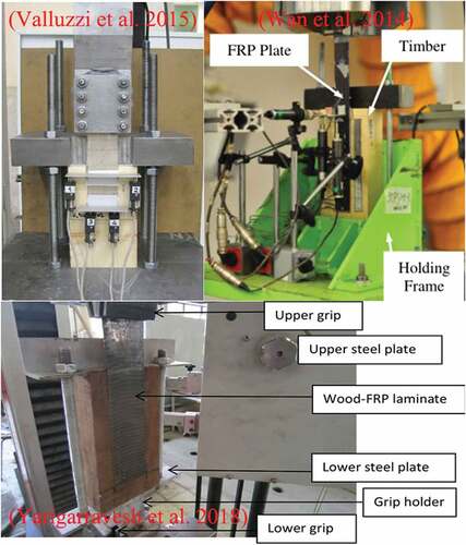
Table 1. FRP width and bond length for FRP-reinforced timber.
There are a few elements that can indicate the debonding process, that is, failure modes, stress-strain distribution, load-displacement relationships, fracture energy and bond-slip relationships (Biscaia et al. Citation2022; Biscaia, Chastre, and Silva Citation2013; He and Xian Citation2017; He, Xian, and Zhang Citation2020; Pan and Xian Citation2019; Pellegrino, Tinazzi, and Modena Citation2008; Teng, Yuan, and Chen Citation2006; Ueda and Dai Citation2004). There are five types of debonding modes at the interface between timber and composites (Miao et al. Citation2019; Teng, Yu, and Fernando Citation2012), in which interfacial failure between timber and adhesive indicates that the plate strength is higher than the interface strength and the FRP meet the reinforcement requirements, and FRP failure indicates that the FRP plate is at maximum utilization (He and Xian Citation2016).
As the bond strength cannot increase when the bond length beyond the EBL, it is necessary to get the knowledge of the EBL to properly design the reinforcement. Many theories define EBL as the bond length over which the contact stress is totally 3% when the ultimate strength was reached. Thus the measure of EBL is experimental, calculated depend on the constitutive law of the stiffener. However the stress-strain relationship of FFRP is nonlinear; the modulus decreases when the deformation exceed a certain value. The feasibility of the application of the models based on liner stiffener on the FFRP-timber interface is unknown.
The interfacial fracture energy (Gf) is a significant parameter in the FFRP-substrate interfacial bond-slip relationship, which is the area contained in the interfacial bond-slip curve and determines the interfacial load-bearing capacity. Based on fracture mechanics theory, the fracture energy of a single lap shear specimen can be derived from the following equation (He and Xian Citation2016).
where
bf - FFRP plate width/mm.
Pu - ultimate bearing capacity of the interface of a single lap shear specimen/kN.
Ef - the modulus of elasticity of the FFRP plate/GPa.
tf - thickness of FFRP plate/mm.
The effect of the elastic deformation of the substrate plays a significant role, and it was believed to be calculated depending on the constitutive law of the reinforced materials, and can be measured by a set of strain gauges. The average bond shear stress and relative slip values at the midpoint between adjacent strain gauges can be calculated according to Equationequations (2)(2)
(2) and (Equation3
(3)
(3) ).
where
τi + 1 - shear stress at the midpoint between thei-th measurement point and the (i + 1) measurement point/MPa.
εi - strain at the i-th measurement point/με.
Ef - modulus of elasticity of the FFRP plate/GPa.
si + 1/2 - the slip between the i-th measurement point and the i + 1st measurement point/mm.
Δxi - distance between the i-th measurement point and the (i + 1) measurement point/mm.
The analysis of the distribution and trend of interfacial bond shear stresses provides an understanding of the mechanism of interfacial shear stress transfer in FFRP reinforced timber substrates. The debonding process is complex, and much models were proposed. In this paper, the applicability of the modified Popovics model for studying the local behavior of the non-linear bonded FFRP-timber interface is verified based on the study by Biscaia et al. and experimental results, where the modified Popovics model expressions are shown below (Biscaia et al. Citation2017):
where
τ0 - maximum shear stress at the interface/MPa.
s0 - the slip corresponding to the maximum shear stress/mm.
τμ - interface shear stress in the horizontal phase/MPa.
sμ - initial slip in the horizontal phase/mm.
With the study of debonding properties, the slope of the bond-slip curve can be established which reflect the stiffness of the bond interface: the greater the stiffness, the stronger the ability to resist the interface slip; the descending section of the curve, which is the ductility of the bonded interface, reflects the bonding capacity of the interface when a large amount of slip is generated. The study of FFRP-timber interfacial bond performance is important for optimizing reinforcement design, and the interfacial bond-slip model between FFRP and timber is the basis for studying the performance of the FFRP reinforced timber structure and is necessary for the establishment of the design model.
Materials and methods
Materials
The substrate is made of first-class Russian pine timber, with straight grain and no defects, provided by Shaanxi Xinyaosen timber Industry Co. Ltd. The mechanical properties of the timber were measured in accordance with GB/T 1928–2009 General requirements for physical and mechanical tests of wood and the mechanical properties of the timber are shown in and . The flax fiber is purchased from Harbin Linen Factory with a theoretical thickness of 0.267 mm, width of 1 m, density of 1.6 g/cm3 and average linear density of 0.067 g/m; TS epoxy resin was used for the preparation of FFRP by hand lay-up, and T1 is used between the FFRP and timber interface. The two adhesives used were supplied by Shandong Dagong Composites Company. The mechanical properties of FFRP and epoxy resins are shown in .
Figure 2. Timber properties testing: (a)flexural properties; (b)tensile properties.
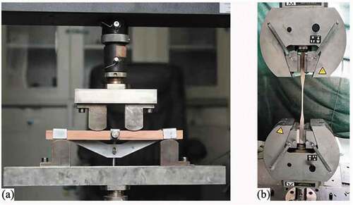
Table 2. Basic material parameters of timber.
Table 3. Tensile properties of resins and FFRP.
Specimen design and loading method
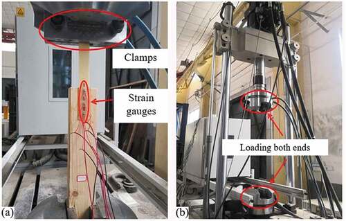
Single lap shear test was conducted to investigate the bonding performance of FFRP to timber in the grain direction. As shown in , an FFRP plate was bonded to one surface of a square timber, the square timber is 100 mm × 100 mm × 400 mm; one side of the timber was selected as the bonding area, the side should be de-dust and cleaned with acetone, then roughed with abrasive paper. Seven strain gauges were attached on the top of the FFRP plate, one strain gauge was at 5 mm from the loaded end of the timber, the others were bonded at with an interval of 30 mm on the FFRP plate. Loading was applied on a fatigue-testing machine (MTS793) by two mutually perpendicular clamp; schematic diagram and test setup are shown in .
Figure 3. Fabrication process of single lap shear specimen.
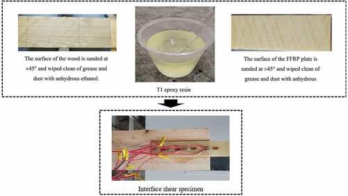
Figure 4. (A)specimen details and (b)test setup.
There are a number of factors that affect the interface load capacity, including loading rate, timber matrix strength, FRP type, impregnating adhesive type, number of layers of fiber cloth bonded and the width ratio of the plate to the timber component. In this study, two main factors such as bond length and width ratio of FFRP to timber members are considered, and the effect of each factor on the bearing capacity of the FFRP-timber interface is investigated by conducting a single lap shear test on the FFRP-timber structure.
The tests were divided into 18 groups with these parameters: (1) different bond lengths (50 mm, 70 mm, 90 mm, 110 mm, 130 mm, 150 mm); (2) different FFRP plate widths (30 mm, 35 mm, 40 mm). The designation of test specimens were F-(bond length)-(plate width), the letter F stands for FFRP, thus F-110-35 is specimen with 35 mm width FFRP and the bond length is 110 mm. The loading speed was controlled by displacement at a rate of 2 mm/min, and the deformation was observed until the specimen was damaged and the loading procedure was stopped manually.
Results and analysis
Failure modes
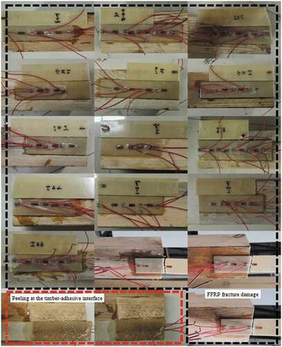
There are mainly two failure modes of FFRP and timber interface: firstly, peeling at the timber-adhesive interface, and secondly, fracture damage to the FFRP plate (). The former failure mode occurs more frequently with a slow peeling process and can be observed during the test: FFRP plate peeled off from the timber with a small sound; fibers of the timber were pulled out within the bonding length, causing a 1–3 mm depth concave on the surface of beneath timber. The latter failure mode is a direct fracture of the FFRP plate with a loud sound and then pulled into two sections with a smooth fracture surface; the damage process is almost instantaneous.
Figure 5. Failure modes of FFRP-timber interface.
During the tests it was also found that even if the curing of the specimens as well as the test environment conditions was the same and the level of the interfacial compounding process was the same, there was still a certain gap in the quality of the adhesion of the specimens and it was difficult to ensure that each specimen was consistent; this feature was demonstrated by the fact that the speed of peeling at the interface of the same batch of composites was not the same for the same bond length in the tests. After the loading level reaches the peeling load, if the peeling process is stable and the load is gradually transferred from the loading end to the free end, then the peeling time is relatively long and the strain near the free end has a large development; if the peeling time is particularly short and the load on the interface exceeds the peeling load-bearing capacity, the FFRP plate and the timber peel off rapidly and the strain near the free end has a small growth.
Load-displacement relationships
The load-displacement relationship of FFRP confined timber is shown in . It shows that the load increases along with the displacement mainly in three stages: the first one is the growth stage, where the load–displacement relationship is approximate linear; the second one is the decline stage, where the load declines after reaching a certain value, the reason is the interface has partially cracked and leads to a decline of the interface loading capacity; the third one is the stability stage, where the displacement increases while the load gradually increases to a certain value and holds till failure.
Figure 6. Load-displacement relationship of: (a) different bond lengths at 30 mm FRP width; (b)different FRP widths at 110 mm bond length.
The critical point load P for the two stages is just beginning to reach the ultimate load Pu. In studies of the relevant bond-slip relationship (Vahedian, Shrestha, and Crews Citation2018; Wan et al. Citation2014) it was shown that the load reaches the ultimate value Pu when the slip s reaches the maximum slip smax. In the single lap shear test, the deformation of the timber substrate can be ignored as the deformation of the timber substrate is much smaller than that of the FFRP plate, so the slip is the displacement of the point on the FFRP plate. When the displacement at the loading end is the maximum slip smax, the load reaches the ultimate load, and the slope of the load-displacement relationship represents the ability of the specimen to resist deformation, i.e. the stiffness of the FFRP-timber interface (Tam et al. Citation2017). The ductility of the interface is defined as the deformation capacity before destruction; the load-displacement relationship curve shows a large deformation of FFRP-timber structure, that also means there is a high ductility for FFRP reinforced timber interface.
Interface bearing capacity and fracture energy
All specimens are loaded to the ultimate damage state, so as to obtain the interface peel bearing capacity, through the EquationEq. 1(1)
(1) to obtain the interface fracture energy of each group of specimens as shown in . It can be seen that for the same width specimen, at the same loading rate, the interface fracture energy increases with the increase of the ultimate bearing capacity; when the bond length reaches a certain value, the interface bearing capacity and fracture energy increase trend becomes slower or remain the same. All specimens were loaded to the ultimate damage state to obtain the interface loading capacity as shown in .
Table 4. Peeling capacity and fracture energy of specimens.
As can be seen from and , the ultimate load capacity of the FFRP-timber interface gradually increases with increasing bond length. For example, for a 40 mm bond width, the ultimate load capacity of each specimen with the same loading rate in a single lap shear test is 3.1% lower than that of the 110 mm specimen and 5.2% higher than that of the 70 mm specimen; the ultimate load capacity of the 150 mm specimen is 3.6% higher than that of the 130 mm specimen and 9.6% higher than that of the 110 mm specimen. It can be seen that the ultimate bearing capacity of the FFRP-timber interface increases with increasing bond length at the same loading rate, but the magnitude of the increase gradually decreases, which is consistent with the results of existing studies on the performance of the FRP-timber interface (Juvandes and Barbosa Citation2012), i.e. the concept of effective bond length exists, when the bond length exceeds this effective bond length, the ultimate bond bearing capacity between the interfaces will no longer increase, or When the bond length is exceeded, the ultimate bond load between the interfaces will no longer increase, or will not increase significantly, but the increase in bond length will slow down the damage process of the bonded surfaces.
Figure 7. Influence of bond length on interface bearing capacity.
As can be seen from and , FFRP-timber interfacial bearing capacity increases with the growth of bond width when other variables are same. For a single lap shear specimen with a bond length of 150 mm, the peel load capacity of the interface between the FFRP plate and the timber member increased by 1.77% compared to that of the interface with a width ratio of 0.375 at a loading rate of 0.4375, while the peel load capacity of the interface with a width ratio of 0.5 increased by approximately 8.32% compared to that of the interface with a width ratio of 0.4375. The increase in interfacial peel load capacity for a width ratio of 0.4375 is about 8.32%. In other words, increasing the width of the FFRP plate essentially increases the overall stiffness of the material, while the interfacial peel load capacity of single lap shear specimens increases with increasing the width ratio of the FFRP to the timber member, but the increase in interfacial peel load capacity decreases with increasing width ratio.
Figure 8. Effect of width ratio on interface bearing capacity.
Effective bond length (EBL)
EBL is an important parameter of the bonding performance between FFRP and timber, and is directly related to the bond strength and the stress-strain distribution of the plates (Vahedian, Shrestha, and Crews Citation2017). The measured values of the EBL for each test are shown in , where the variance of the data is given in brackets.
Table 5. Test result of specimens.
As can be seen from , all the EBL between the FFRP plate and the timber substrate is mainly concentrated in the range of 95 mm to 105 mm. As the bond length increased, both the ultimate interfacial load-bearing capacity and the measured value of the effective bond length have a limited growth. When the width of FFRP plates is 30 mm, the average EBL of is 97.7 mm; when the width 35 mm, the effective bond length is 101.3 mm, which is about 3.7% higher than the width of 30 mm; while when the width is 40 mm, the average EBL is 99.8 mm, which is about 2.1% higher than the width of 30 mm, but 1.5% lower than the width of 35 mm. It means that the effective bond length of the FFRP plate does not always increase with the growing width of the FFRP. In this paper, the proper width of FFRP plate is 35 mm, and the measured EBL is in the range of 95 mm to 105 mm, which means the EBL is closed to the one of linear elastic FRP confined timber.
Strain distribution
The strain shapes of the specimens are mostly similar, and when the FFRP plate is stripped before, i.e. the load level of 0.1Pu, 0.3Pu and 0.6Pu, the FFRP plate axial strain distribution can be obtained as follows: for the same measurement point, the strain for the larger load is greater than the strain corresponding to the smaller load; for the same load level, as shown in , the strain at the measurement point near the loading end is greater than the strain away from the loading end. The strain distribution is concentrated in the region close to the loading end, which transferred toward the free end as the load increases. And when the load reaches the ultimate load, i.e. the load level of 0.8Pu, 0.9Pu and 1Pu, peeling damage starts to occur at the interface, the strains are equal near the loading area.
Figure 9. FFRP plate strain distribution diagram: (a)f-110-30; (b)f-150-30.
The distribution of the axial strain in the FFRP plate shows the whole process of damage at the interface: when the load is small, the externally load is mainly borne by the area near the loading end. As the load increases, the bearing area becomes progressively larger. When the load reaches the ultimate load of the interface, the length of the load-bearing area peaked and the plate starts to peel off. As the load continues applied, the increases of load stops, the displacement continues to increase and the peel is transferred to the free end. Until the remaining bond length after peeling is less than the effective bond length, the specimen is damaged.
Bond stress distribution
The average bond shear stress and relative slip values at the midpoint between adjacent strain gauges can be calculated according to Equationequations (2)(2)
(2) and (Equation3
(3)
(3) ). shows the distribution curve of the interfacial bond shear stress along the bond length of the flax fiber composite plate at different load levels.
Figure 10. Distribution of shear stresses at various load levels: (a) F-150-30; (b)f-150-35.
As can be seen from the above figures, the shear stress distribution curves of each FFRP-timber specimen are generally similar, and can be summarized as follows: (1) the interface shear stress values are small at the beginning of loading, when the shear stress is mainly concentrated in the range of 45 mm from the loading end, showing a sloping straight line downward distribution, while the shear stress values at the farther end from the loading end are zero basically, that indicating that the load transfer area is short at this time; (2) as the load continues to increase, the FFRP-timber interface shear stress is gradually transferred to the free end of the FFRP plate, and the shear stress curve gradually becomes steeper; the shear stress value at the loading end keeps increasing, then the maximum value of shear stress at the loading end appears when the load is loaded to a certain value; (3) As the load continues to increase, the shear stress at the loading end decreases, while the increase in shear stress at the free end increases significantly and stress concentration occurs near the free end; when the ultimate load is approached, the value of shear stress at the loaded end drops obviously and the peak interface shear stress gradually migrates from the loaded end to the free end, and the FFRP-timber interface begins to break down until the interface is completely stripped to damage.
Load-slip curves
As the stiffness of the timber substrate is much greater than that of the FFRP plate, the deformation of the timber substrate is neglected, i.e. the slip s is the displacement of the FFRP plate. The study of the axial strain distribution of the FFRP plate shows that there is basically no strain development at the free end of the FFRP plate, so the slip at the free end is assumed to be zero in this study. The local bond shear stress-slip relationship curves for single lap shear specimens with different bond lengths and bond widths of FFRP plates are shown in .
Figure 11. Interface local bond-slip curve: (a)f-90-30; (b)f-150-30; (c)f-90-35; (d)f-110-40.
As can be seen from , different bond lengths and widths have an effect on the shear stress and slip at the FFRP-timber interface, but the shape of the curve at different measurement points can be classified into three parts: rising, falling and horizontal parts. The interfacial shear stress increases rapidly with the increase of slip, and decreases rapidly when the slip reaches about 0.1 mm. It can also be found that to obtain a complete bond-slip model it is necessary to determine the maximum bond shear stress τmax, the slip value corresponding to the maximum shear stress s0 (or initial stiffness k0), the fracture energy Gf and the maximum relative slip sμ and other relevant control parameters.
Fitting of load-slip curves
A statistical regression analysis of the test results with a modified Popovics model yielded the bond-slip relationship curve shown in .
Figure 12. Fitting curve of bond-slip relationship of FFRP-timber interface: (a)f-90-30; (b)f-150-30; (c)f-90-35; (d)f-110-40.
As can be seen from the above figures, the modified Popovics model fits well with the results of the FFRP-timber interface bonding tests, and can well reflect the gradual reduction in bond stiffness of the FFRP board-timber interface to complete peel-off damage of the interface during the softening and constant phases, but they are slightly different in descending section, which is mainly due to uneven degradation of the interfacial adhesive layer. The correction factor n for specimen F-90-30-2 was 4.4, for specimen F-150-30-2 it was 7.4 and for F-90-35-1 it was 4.2. It can be seen that at the same loading rate of the single lap shear test, the smaller the relative slip of the specimen from the start of loading to the horizontal stabilization phase, the smaller the opening between the rising and falling phases of the bond-slip relationship curve and the larger the correction factor n value is. The modified bond-slip relationship curve using the n value is consistent with the test trend and the error is small.
Conclusion
The bonding performance of FFRP-timber interface is the key to understanding the interfacial properties between FFRP and timber structure; this paper mainly conducts the analysis of the interface bonding performance from experimental research results, observes the main failure modes of the specimens, summarizes the interface mechanical properties of the specimens, analyses the bonding mechanism of FFRP with non-linear, large deformation and timber structure, and obtains the following conclusions:
Peel damage is the main failure mode of FFRP-timber interface, it is needed to ensure the bonding properties between FFRP and the timber structure; the other failure mode is the fracture of FFRP plate, the application of FFRP should be well produced to avoid premature damage before interface peeling.
The deformation of the interface can be classified as high ductility, the EBL of FFRP-timber is 95−105 mm, the optimized width of FFRP is 35 mm in the present study. According to the stress distribution in the interface, the force process at the FFRP-timber interface is a gradual transfer of interfacial stresses from the loaded end to the free end.
The modified Popovics model can describe the bonding behavior of the FFRP-timber structure and fits the bond-slip curve characteristics of the interface. This model can be used as the intrinsic model for the bond-slip relationship at the interface of non-linear materials reinforced structure, which provides a reference for the application and design calculation of actual ancient timber building reinforcement projects.
Disclosure statement
No potential conflict of interest was reported by the author(s).
Additional information
Funding
References
- Athijayamani, A., M. Thiruchitrambalam, V. Manikandan, and B. Pazhanivel. 2010. Mechanical properties of natural fibers reinforced polyester hybrid composite. International Journal of Plastics Technology 14 (1):104–17. doi:10.1007/s12588-009-0016-0.
- Biscaia, H. C., J. Canejo, S. Zhang, and R. Almeida. 2022. Using digital image correlation to evaluate the bond between carbon fibre-reinforced polymers and timber. Structural Health Monitoring 21 (2):534–57. doi:10.1177/14759217211006021.
- Biscaia, H. C., C. Chastre, I. S. Borba, C. Silva, and D. Cruz. 2016. Experimental evaluation of bonding between CFRP laminates and different structural materials. Journal of Composites for Construction 20 (3):04015070.04015071–04015070.04015015. doi:10.1061/(ASCE)CC.1943-5614.0000631.
- Biscaia, H. C., C. Chastre, D. Cruz, and A. Viegas. 2017. Prediction of the interfacial performance of CFRP laminates and old timber bonded joints with different strengthening techniques. Composites Part B: Engineering 108 (jan.):1–17. doi:10.1016/j.compositesb.2016.09.097.
- Biscaia, H. C., C. Chastre, and M. Silva. 2013. Linear and nonlinear analysis of bond-slip models for interfaces between FRP composites and concrete. Composites Part B: Engineering 45 (1):1554–68. doi:10.1016/j.compositesb.2012.08.011.
- Biscaia, H. C., D. Cruz, and C. Chastre. 2016. Analysis of the debonding process of CFRP-to-timber interfaces. Construction and Building Materials 113:96–112. doi:10.1016/j.conbuildmat.2016.03.033.
- Borri, A., and M. Corradi. 2011. Strengthening of timber beams with high strength steel cords. Composites Part B: Engineering 42 (6):1480–91. doi:10.1016/j.compositesb.2011.04.051.
- Borri, A., M. Corradi, and E. Speranzini. 2013. Reinforcement of wood with natural fibers. Composites Part B: Engineering 53 (oct.):1–8. doi:10.1016/j.compositesb.2013.04.039.
- Fernandes, R., M. De Moura, and R. Moreira. 2016. Effect of temperature on pure modes I and II fracture behavior of composite bonded joints. Composites Part B: Engineering 96:35–44. doi:10.1016/j.compositesb.2016.04.022.
- Franke, S., B. Franke, and A. M. Harte. 2015. Failure modes and reinforcement techniques for timber beams – State of the art. Construction and Building Materials 97 (oct.30):2–13. doi:10.1016/j.conbuildmat.2015.06.021.
- Ghoroubı, R., Ö. Mercimek, S. Sakın, and Ö. Anıl. 2021. Novel bond-slip model between concrete and angular CFRP fan type anchoraged CFRP strip. European Journal of Environmental and Civil Engineering 26 (11):1–19. doi:10.1080/19648189.2021.1899990.
- Gomez, S., and D. Svecova. 2008. behavior of split timber stringers reinforced with external GFRP sheets. Journal of Composites for Construction 12 (2):202–11. doi:10.1061/(ASCE)1090-0268(2008)12:2(202).
- He, J., and G. Xian. 2016. Debonding of CFRP-to-steel joints with CFRP delamination. Composite Structures 153:12–20. doi:10.1016/j.compstruct.2016.05.100.
- He, J., and G. Xian. 2017. Bond-slip behavior of fiber reinforced polymer strips-steel interface. Construction and Building Materials 155 (nov.30):250–58.
- He, J., G. Xian, and Y. X. Zhang. 2020. Effect of moderately elevated temperatures on bond behaviour of CFRP-to-steel bonded joints using different adhesives. Construction and Building Materials 241:118057. doi:10.1016/j.conbuildmat.2020.118057.
- Hoseinpour, H., M. R. Valluzzi, E. Garbin, and M. Panizza. 2018. Analytical investigation of timber beams strengthened with composite materials. Construction and Building Materials 191:1242–51. doi:10.1016/j.conbuildmat.2018.10.014.
- Işleyen, Ü. K., R. Ghoroubi, Ö. Mercimek, and Ö. Anil. 2021a. Behavior of glulam timber beam strengthened with carbon fiber reinforced polymer strip for flexural loading. Journal of Reinforced Plastics and Composites 40 (17–18):073168442199792. doi:10.1177/0731684421997924.
- İ̇şleyen, Ü. K., R. Ghoroubi, Ö. Mercimek, Ö. Anil, A. Togay, and R. T. Erdem. 2021b. Effect of anchorage number and CFRP strips length on behavior of strengthened glulam timber beam for flexural loading. Advances in Structural Engineering 24 (9):1869–82. doi:10.1177/1369433220988622.
- Juvandes, L. F. P., and R. M. T. Barbosa. 2012. Bond analysis of timber structures strengthened with FRP systems. Strain 48 (2):124–35. doi:10.1111/j.1475-1305.2011.00804.x.
- Kabir, M. I., R. Shrestha, and B. Samali. 2016. Effects of applied environmental conditions on the pull-out strengths of CFRP-concrete bond. Construction and Building Materials 114 (jul.1):817–30. doi:10.1016/j.conbuildmat.2016.03.195.
- Khelifa, M., and A. Celzard. 2014. Numerical analysis of flexural strengthening of timber beams reinforced with CFRP strips. Composite Structures 111 (may):393–400. doi:10.1016/j.compstruct.2014.01.011.
- Kilincarslan, S., and Y. S. Turker. 2021. Experimental investigation of the rotational behaviour of glulam column-beam joints reinforced with fiber reinforced polymer composites. Composite Structures 262 (1):113612. doi:10.1016/j.compstruct.2021.113612.
- Klnarslan, E., and Y. Türker. 2020. Investigation of wooden beam behaviors reinforced with fiber reinforced polymers. Organic Polymer Material Research 2 (1):7. doi:10.30564/opmr.v2i1.1783.
- Ku, H., H. Wang, N. Pattarachaiyakoop, and M. Trada. 2011. A review on the tensile properties of natural fiber reinforced polymer composites. Composites: Part B 42 (4):856–73. doi:10.1016/j.compositesb.2011.01.010.
- Lemos, A. L. D., P. G. P. Pires, M. L. D. Albuquerque, V. R. Botaro, J. M. F. D. Paiva, and N. Domingues. 2017. Biocomposites reinforced with natural fibers: Thermal, morphological and mechanical characterization. Matéria (Rio de Janeiro) 22 (2). doi:10.1590/s1517-707620170002.0173.
- Li, Y., M. Tsai, T. Wei, and W. Wang. 2014. A study on wood beams strengthened by FRP composite materials. Construction and Building Materials 62:118–25. doi:10.1016/j.conbuildmat.2014.03.036.
- Li, J., X. Zhang, J. Li, R. Li, M. Qian, and P. Song. 2017. An experimental study of the damage degrees to ancient building timber caused by lightning strikes. Journal of Electrostatics 90:23–30. doi:10.1016/j.elstat.2017.08.009.
- Lopez-Anido, R. A., L. Muszynski, D. J. Gardner, B. Goodell, and B. Herzog. 2005. Performance-based material evaluation of reinforced glued laminated timber (Glulam) beams. Journal of Testing and Evaluation 33:6.
- Malkapuram, R., V. Kumar, and Y. S. Negi. 2009. Recent development in natural fiber reinforced Polypropylene composites. Journal of Reinforced Plastics and Composites 28 (10):1169–89. doi:10.1177/0731684407087759.
- Miao, C., D. Fernando, M. T. Heitzmann, and H. Bailleres. 2019. GFRP-to-timber bonded joints: adhesive selection. International Journal of Adhesion and Adhesives 94:29–39. doi:10.1016/j.ijadhadh.2019.05.007.
- Morales-Conde, M. J., C. Rodriguez-Linan, and P. Rubio-De Hita. 2015. Bending and shear reinforcements for timber beams using GFRP plates. Construction and Building Materials 96 (oct.15):461–72. doi:10.1016/j.conbuildmat.2015.07.079.
- Pan, Y., and G. Xian. 2019. Influence of long-term outdoor exposure in a frigid zone on the CFRP-to-concrete bond behavior. Construction and Building Materials 215 (AUG.10):462–74. doi:10.1016/j.conbuildmat.2019.04.198.
- Pellegrino, C., D. Tinazzi, and C. Modena. 2008. Experimental study on bond behavior between concrete and FRP reinforcement. Journal of Composites for Construction 12 (2):180–89. doi:10.1061/(ASCE)1090-0268(2008)12:2(180).
- Raftery, G. M., A. M. Harte, and P. D. Rodd. 2009a. Bond quality at the FRP–wood interface using wood-laminating adhesives. International Journal of Adhesion and Adhesives 29 (2):101–10. doi:10.1016/j.ijadhadh.2008.01.006.
- Raftery, G. M., A. M. Harte, and P. D. Rodd. 2009b. Bonding of FRP materials to wood using thin epoxy gluelines. International Journal of Adhesion and Adhesives 29 (5):580–88. doi:10.1016/j.ijadhadh.2009.01.004.
- Rescalvo, F. J., E. Suarez, C. Abarkane, A. Cruz-Valdivieso, and A. Gallego. 2019. Experimental validation of a CFRP laminated/fabric hybrid layout for retrofitting and repairing timber beams. Mechanics of Advanced Materials and Structures 26 (22):1902–09. doi:10.1080/15376494.2018.1455940.
- Sakin, S., Ö. Anil, R. Ghoroubi, and Ö. Mercimek. 2019. Modelling bond between concrete and bonded and anchored carbon-fibre polymer strips. Proceedings of the Institution of Civil Engineers 172 (6):437–50. doi:10.1680/jstbu.18.00003.
- Tam, L. H., A. Zhou, Z. Yu, Q. Qiu, and D. Lau. 2017. Understanding the effect of temperature on the interfacial behavior of CFRP-wood composite via molecular dynamics simulations. Composites: Part B 109 (jan.):227–37. doi:10.1016/j.compositesb.2016.10.030.
- Teng, J. G., H. Yuan, and J. F. Chen. 2006. FRP-to-concrete interfaces between two adjacent cracks: Theoretical model for debonding failure. International Journal of Solids and Structures 43 (18–19):5750–78. doi:10.1016/j.ijsolstr.2005.07.023.
- Teng, J. G., T. Yu, and D. Fernando. 2012. Strengthening of steel structures with fiber-reinforced polymer composites. Journal of Constructional Steel Research 78 (4):131–43. doi:10.1016/j.jcsr.2012.06.011.
- Ueda, T., and J. Dai. 2004. New shear bond model for FRP–concrete interface – from modeling to application. FRP Composites in Civil Engineering - CICE 2004 14:69–82. doi:10.1201/9780203970850.ch6.
- Ungureanu, D., N. Taranu, I. Hudisteanu, I. Florenţa, and V. Lupășteanu. 2017. Shear structural response of adhesive joints for FRP composites. Advanced Engineering Forum 21:280–85.
- Vahedian, A., R. Shrestha, and K. Crews. 2017. Effective bond length and bond behaviour of FRP externally bonded to timber. Construction and Building Materials 151 (oct.1):742–54. doi:10.1016/j.conbuildmat.2017.06.149.
- Vahedian, A., R. Shrestha, and K. Crews. 2018. Bond strength model for externally bonded FRP-to-timber interface. Composite Structures 200 (SEP.):328–39. doi:10.1016/j.compstruct.2018.05.152.
- Valluzzi, M. R., F. Nardon, E. Garbin, and M. Panizza. 2015. Multi-scale characterization of moisture and thermal cycle effects on composite-to-timber strengthening. Construction and Building Materials 102:102. doi:10.1016/j.conbuildmat.2015.07.008.
- Vanerek, J., A. Benesova, P. Rovnanik, and R. Drochytka. 2014. Evaluation of FRP/wood adhesively bonded epoxy joints on environmental exposures. Journal of Adhesion Science and Technology 28 (14–15):1405–17. doi:10.1080/01694243.2012.698096.
- Wang, Z., X. L. Zhao, G. Xian, G. Wu, R. Raman, and S. Al-Saadi. 2017. Durability study on interlaminar shear behaviour of basalt-, glass- and carbon-fibre reinforced polymer (B/G/CFRP) bars in seawater sea sand concrete environment. Construction and Building Materials 156 (15):985. doi:10.1016/j.conbuildmat.2017.09.045.
- Wan, J., S. T. Smith, P. Qiao, and F. Chen. 2014. Experimental investigation on FRP-to-timber bonded interfaces. Journal of Composites for Construction 18 (3) Article Number: A4013006. doi:10.1061/(ASCE)CC.1943-5614.0000418.
- Yarigarravesh, T., and Mofid. 2018. Environmental effects on the bond at the interface between FRP and wood. European Journal of Wood and Wood Products 76 (4):1–12. doi:10.1007/s00107-017-1201-z.
- Zhou, A., L. -H. Tam, Z. Yu, and D. Lau. 2015. Effect of moisture on the mechanical properties of CFRP–wood composite: An experimental and atomistic investigation. Composites Part B: Engineering 71:63–73. doi:10.1016/j.compositesb.2014.10.051.