
ABSTRACT
With many offshore wind turbines (OWTs) approaching the end of their estimated service life, there is an increasing demand for developing and evaluating end-of-life strategies that can maximize these assets’ value while at the same time satisfying the requirements of the stakeholders involved. This study aims to perform a detailed review and develop a framework that will consider multiple criteria in the decision-making process, presenting and discussing available technologies and strategies, as well as influencing factors such as schedule, cost and environmental impact. Service life extension, repowering and decommissioning are included in this review as the main end-of-life strategies considered by asset owners, and these are translated into four processes that are applicable to offshore wind farms through a generic decision tree. A SWOT analysis is also conducted which aims to compare the different characteristics of the proposed processes. The factors contributing to the uncertainty of the processes as well as lessons learnt from the oil & gas industry are also discussed.
1. Introduction
Offshore wind energy is probably the most rapidly developing renewable energy technology at the moment, aiming to contribute actively to the net-zero targets that have been established in the EU and beyond for the next decades. This is due to the increased wind shear offshore, the higher capacity units and farms that can be deployed, and the reduced competition to alternative uses of the marine environment (Cevasco, Koukoura, and Kolios Citation2021). Research since the first installation of offshore wind farms (OWFs), which took place in 1991 in Denmark, has mainly focused on qualifying technologies around the development, construction, operation, and maintenance of offshore wind energy assets with a view to reducing costs (mainly capital expenditure, CAPEX), while the fate of assets after their nominal design lifetime, which is normally about 20–25 years, has received less attention, although this phase is expected to come at a considerable cost if suboptimal decisions are taken (Topham and McMillan 2017; Hou et al. Citation2017).
Onshore wind energy, has accumulated considerable experience during the past decades, with around 70,000 MW of Europe’s installed wind power reaching its estimated end of life by the year 2030 (Martínez et al. Citation2018). This translates to an increase of more than 460% in demand for end-of-life activities within the next 10 years. Although many lessons can be transferred from onshore to offshore wind energy assets, several aspects have not been resolved; particularly the methods for disposing of composite materials or the ways that can serialize processes to multiple units. The offshore environment involves a number of parameters and influencing factors that need to be considered in order to support decisions related to end-of-life strategies, and it is imperative to consider such factors in the design and development stages of a project in order to avoid unexpectedly higher costs and associated environmental impacts (Kerkvliet and Polatidis Citation2016).
Decommissioning, which is the ultimate end-of-life strategy to be considered for an asset, is defined as the process of disassembling the wind turbine (WT) with a view to returning the site to its pre-installation phase, to the extent this is possible (Kaiser Citation2015; Topham and McMillan 2017). The first decommissioning of an OWF was done in 2017 to the Vindeby wind farm in Denmark, due to the difficulty in finding spare parts as a result of technology obsolescence and the considerable costs associated with repairs and upgrades after 25 years of operation. Due to the development of many offshore projects in the early 2000s and the approaching end-of-life dates for the installed OWFs (Shafiee and Animah Citation2017), a high number of decommissioning projects is expected in the coming years. Decommissioning is a technology and energy-intensive process, with significant emissions of greenhouse gases and considerable amounts of waste that cannot yet be recycled.
Reusing an existing installation can be a valid strategy to reduce environmental pollution and delay high decommissioning expenses (Bull and Love Citation2019; Kaiser and Snyder Citation2010). To this end, alternative strategies that can proceed decommissioning can be repowering and service life extension. Service life extension is the process of evaluating the current integrity state of the asset, with a view to evaluating its residual service life and issuing a certificate of fitness-for-purpose for an extended period. Repowering is the process of substituting critical sub-systems/components of an asset, such as generator and blades, potentially with more technologically advanced components, which can harvest more of the energy potential, while maintaining subsystems designed for a longer nominal life such as the tower and electrical infrastructure (also known as the balance of plant, BOP). Both processes are influenced by the confidence in evaluating the integrity of the structure after 20–25 years of operation and, in the case of repowering, the capacity of the electrical infrastructure to handle the maximum load.
Although the need for systematic research around end-of-life strategies of offshore wind farms has been recognized, a detailed review of the literature has revealed a lack of appropriate frameworks which can direct decisions on available strategies based on the special characteristics and influencing factors (i.e. the number and types of WTs, types of foundations, weather, and seabed conditions as well as available technologies and environmental requirements). Considering that each wind farm and even different WTs across the farm should be assigned a unique strategy that will maximize profit while fulfilling technological, safety, and environmental constraints, constitutes the development of such decision support frameworks, as tasks of paramount importance. To this end, this paper performs a multi-attribute review toward the effective planning of end-of-life strategies for offshore wind farms. To do this, alternative strategies and associated technological options are presented, together with the associated influencing factors to be considered, resulting in a decision support framework that can inform decisions. Previous research in this domain has not considered all of the available strategies, i.e. service life extension, repowering, or decommissioning; hence this paper can provide the context for future studies that can quantify the technical and economic assessment of specific case studies and scenarios, which will subsequently facilitate planning and reduce the uncertainty of end-of-life operations.
The paper is structured as follows. After this introduction, the different end-of-life strategies are presented in detail in Section 2, followed by an explicit discussion on factors influencing related decisions in Section 3. Then, a critical discussion is included on lessons learned by the oil & gas industry, which has previously faced similar challenges (Section 4). Section 5 discusses the findings and presents a high-level framework, while some conclusions are drawn in Section 6.
2. End-of-life strategies
This section will discuss the various challenges involved in the process of selecting end-of-life strategies for offshore wind energy assets, starting from decommissioning and then moving to service life extension and repowering, presenting different options and influencing factors that should be considered.
2.1. Decommissioning
The decommissioning process can be defined as the reversal of the installation process; thus, it is expected to have similar constraints (Januário, Semino, and Bell Citation2007), but with the additional complexity of the marginal value of the asset at the time. The decommissioning process starts with disconnecting the WT from the grid and de-energizing it, followed by the blade, nacelle, and tower removal (Ortegon, Nies, and Sutherland Citation2013). The foundation may either be partially or fully removed. Partial removal of the foundation leaves some parts in place, such as the scour protection, cables, or even a part of the actual foundation, while total removal considers the disposal of all components of the wind farm; in both cases though the aim should be that the site is returned to its pre-installation state (Smyth et al. Citation2015).
2.1.1. Turbine removal
The different options for the disassembly process are generally similar to those for the installation process, with the size of turbines and the weight of modules standing as key influencing factors (Kaiser and Snyder Citation2012). Generally, after isolating and de-energizing the turbine from the grid, the disassembly of the turbine involves the removal of lubricants, blades, hub nacelle, and the tower. Disassembling is presumably as costly as an installation because similar vessels (such as a heavy lift or dynamic positioning vessel) are needed. The removal of a turbine can be done in 1 to 6 lifts, and then all the components can be transported for reuse, recycling or disposal (Miñambres and Garcia Citation2020; A. Ioannou, Angus, and Brennan Citation2018). A reduced number of lifting operations can reduce safety risks and expected duration but usually require larger vessels which come with a more extended lead time and higher costs.
After removal of the rotor, any chemical liquids (such as gear or motor oil) should be collected and removed from the turbine or kept inside the nacelle to reduce the risk of spillage or dropped objects. The removal of bolts and apparatuses can then be done using standard practices, or angle grinders and plasma cutters, followed by the cutting of interconnecting cables to adjacent structures. Furthermore, preparation for the removal of the foundation can be done when the tower is lifted. Important factors to consider are risks to personnel involved, operating time exposure, costs and environmental conditions when deciding the removal options (Topham et al. Citation2019b).
2.1.2. Foundation
The selection of operation depends on the type of foundations, as specific vessels are needed for lifting heavy foundations/modules. Initially, the J-tubes, which are responsible for the output of cables from the foundation for connection to the inter-array cables, are removed, allowing internal access to the foundation. The foundation may then be either partially or fully removed.
Partial removal accounts for cutting of the foundation no less than 2 m below the mud line, while leaving the remaining parts on/under the ground. After removing the foundation, it is necessary to cover the hole by landfilling. This is based on the assumption that after 20–25 years since initially disturbing the local environment, a new natural ecosystem has been developed and it is unnecessary to cause a new disturbance (Scira Offshore Energy Citation2014). This approach is becoming prevalent due to the lower risks and costs involved, as the removal of certain components, such as the piles and cables, come at a high cost and can cause significant disturbance to the environment.
Several methods are implemented to remove the foundation, including, but not limited to, external cutting, internal cutting, and the use of explosives. Cutting of the monopile is carried out in various steps based on the cutting stage involved, i.e. external cutting or internal cutting (Kaiser Citation2015; Smith and Lamont Citation2017). Internal cutting involves dredging or pumping away the mud to create an execution pit to enable the cutting and removal of the pile. After this step, it would be possible to cut the monopile and remove it. The pit should be filled with mud again after the execution of the job (Kaiser and Snyder Citation2012, Citation2010).
The type of foundation plays a critical role in the removal operation. The decommissioning processes for various types of foundations are presented below:
2.1.2.1. Monopiles
An initial inspection of the piles at the site is recommended to determine the lifting equipment and attachments required. The inspection can be done by divers or remotely operated vehicles (ROVs). The vessels such as a floating crane or a jack-up barge can be mobilized and assembled for operation at the site. The crane hooks are attached to the foundation and the piles are cut below the seabed. The distance between the seabed and cutting position is based on the type of seabed and the removal method used. Influencing factors of the removal process are the pile size, weight, and depth of penetration into the seabed. Apart from this, the total foundation removal for the monopiles involves higher risk to personnel, increased costs, and negative environmental effects due to the need for more complex excavation processes. Specialized equipment is needed for such an excavation as greater depths below the seabed need to be reached.
Tow cutting using diamond wire cutting or ultra-high-pressure water jetting can be used for the cutting process, depending on the method’s effectiveness in preventing unnecessary damage and its ability to remove debris from the site. The detached foundation is then loaded onto the chosen transportation vessel and shipped when the vessel has full capacity (Topham and McMillan 2017). Tow cutting may undertake external or internal cut strategies (Kaiser and Snyder Citation2010, Citation2012; Kerkvliet and Polatidis Citation2016). Seabed depth and the possibility of excavation surrounding the seabed are the two main factors impacting the external pile cutting. However, internal cutting can be preferable as it is not affected by water currents; it can be implemented from above the platform and through the pile top (Smith, Garrett, and Gibberd Citation2015).
Selection of the cutting procedure should be aimed, where possible, at enabling a single lift to save the costs of repeated vessel hiring for the transportation of the decommissioned monopile and transition piece; however, it is important to consider the water depth limitation while selecting the appropriate strategy (Smith et al. Citation2016). Each of the available methods has its own set of financial and environmental risks. Issues arising in either strategy have significant impacts on the project completion timelines due to the need for necessary repairs, remote operation of the system, and confined space (Hinzmann et al. Citation2017; Hou et al. Citation2017; Jardine, Standing, and Chow Citation2006). Apart from these, the pile diameter and wall thickness affect the cutting times as well. The part of the monopile that remains under the seabed after partial removal of the foundation limits any future operation with jack-up legs and presents a potential risk for fishing nets. The cutting methods can be replaced by using some new strategies and operations, such as vibration, internal dredging, jet grouting, and buoyancy force and air pressure (Hinzmann, Stein, and Gattermann Citation2018; Massarsch, Fellenius, and Bodare 2017). These methods contribute to full decommissioning of the foundation.
Vibratory pile driving is another common method of pile installation and removal. The process is based on the reduction of shear resistance and the resistance of the pile shaft by using a vibro hammer (which is connected to the head of pile) at 10 to 40 Hz to stimulate the soil to an acceptable liquefaction level. The crane then pulls out the pile and hammer. Internal dredging, airlifting, and excavation are used to remove the soil inside the monopile. A high-pressure jet from the jet nozzles of the dredging toll weakens the sand, clay, and debris, while the jet pressure is determined by the soil condition and density. External jet drilling or jet grouting uses a cutting fluid composed of water, soil, and binder suspension to cut and destroy the surrounding soil and granular structure when used at pressures of 30 to 60 MPa. Moreover, the problem of breakout resistance could be overcome using the buoyancy force or air pressure. The implementation of the buoyancy force allows the removal of the pile out of the seabed, while the in-built air-pressure in the pile guides the pile to a crane by using a gripper (Massarsch, Fellenius, and Bodare 2017; Hinzmann, Stein, and Gattermann Citation2018). This method of removal is most suited to shallower waters.
2.1.2.2. Jacket
Jacket foundations are valid options as we transition to deeper waters and before floating foundations become economically feasible (Martin et al. Citation2013; A. J. Kolios, Rodriguez-Tsouroukdissian, and Salonitis Citation2014). Jacket legs are normally smaller in size than monopiles, hence the requirements for cutting are more limited. Initially, each leg is cut at the selected level below the seabed, followed by lifting. The legs include the pile under the seabed, sub-pile under the structure, and the grout between them to ensure positioning. Before cutting the legs, it is essential to install the rigging equipment on the jacket from the crane vessel. After excavating the seabed near the foundation, a diamond wire cutting tool is used with the help of ROVs. The process may proceed via one-cut, one-lift, or two-cuts, two-lifts, depending on the depth of the sea and the overall weight of the jacket; however, the former strategy is preferable due to less time and preparation being required. The jacket can easily be lifted and transported by a vessel after the legs are cut (Transmission Capital Citation2013; Topham and McMillan 2017; Smith et al. Citation2016).
2.1.2.3. Gravity-based
Gravity-based foundations have been successfully deployed, mainly in shallow water wind farms, due to their suitability to work in rocky or sandy soils, their high bearing capacity, where pile driving can be complicated, and their potential for reduced costs (Esteban, López-Gutiérrez, and Negro Citation2019). It is necessary to provide the base structure integrity as well as the lifting attachment. The ballast which belongs to the base should be removed and disposed of, and then the vessel which is capable of suction dredging needs to be mobilized. The process should be inspected by ROVs or divers for confirmation. The foundation can be lifted out from the seabed by disaggregating compacted sediments which are under the foundation. After lifting and vessel-loading of the foundation, the seabed is monitored for any debris to be removed (Topham and McMillan 2017; Smith et al. Citation2016).
2.1.2.4. Suction bucket
A suction bucket is open at the bottom and completely sealed at the top, like an upturned bucket. It is penetrated into the seabed to a certain depth under its own weight, with the outlet valves on the top open to allow water inside the caisson escape (Plodpradit et al. Citation2020). The foundation can be separated from the seabed by pumping pressure into the bucket. The structure becomes buoyant by pumping the seawater or ballast inside the foundation, making it easier to transfer the structure to the vessel for transportation. This method has a low environmental impact as no excavation or cutting is required, and the foundation is fully removed from the root.
2.1.3. Transition piece
This structure is used to connect the lower part of the tower to the foundation by using a bolted flange or grouted connection. It includes elements such as J-tube cable guides, access ladders and platforms, and weighs around 300 tonnes (Greater-Gabbard-Offshore-Winds-Limited Citation2007). The lifting operation will only be possible after disconnecting and cutting the cables connected to the tower and foundation. While cutting the J-tube, the cutting tool should be fitted to the airtight platform of the transition piece. The transition piece will be cut when the crane is in the position to support the load. The transition piece and foundation can be lifted together as well; however, this lift may become heavier than 1000 tonnes and thus require more safety measures and specialized cranes (Kaiser and Snyder Citation2012).
2.1.4. Cables
There are two types of cables; inter-array cables and export cables buried more than a meter under the seabed. Buried cables do not pose a significant risk to marine life and hence are considered to have a lower environmental impact (Manago 1997). Further, removing the buried cables is a cost-intensive process as constant monitoring with ROVs is required to ensure minimum damage to and from the cable. At crossings of the buried cables, flow execution and grapnels are used to take out the cable from the seabed, followed by cutting of the selected length. Afterward, the cut cables are measured while the rest are returned to the seabed or lifted onto the vessel.
Complete removal of the cables is challenging because of its negative environmental effects regarding seabed damage and disruption. Leaving the cables in situ and buried is an appropriate choice; however, it is possible to reuse or refurbish the cables made of copper, aluminum, and cross-linked polyethylene, which can be used as electrical insulation (Smith et al. Citation2016). It is important to note that more research is required to develop methods of pulling out the cables cost-effectively and with lower environmental risk.
2.1.5. Scour protection
Scour is the phenomenon caused by the movement of the seabed and jeopardizes the operating capacity of offshore structures since it compromises their stability (Matutano et al. Citation2013). Scour protection prevents the exposure of piles during this movement and, as assets reach the end of their service life, scour protection may be left on the site or removed. Removing it will require dredging and shipping to potentially reuse it at another site. Removal of scour protection has similar environmental risks to those associated with its installation.
2.1.6. Vessel options
Using appropriate logistics arrangements for the decommissioning process is essential at the planning phase of any operation. The selection of vessel(s) should be based on the potential for lower risks, cost, and the time of operation. Various types of vessels are available. Important considerations for this include the number of turbines in the farm, the weight of the foundation and the method used for its removal, water depth and the type of seabed, and the availability of the vessel in the market. The latter element is particularly relevant as it is expected that in the next few years, the same vessels will compete for installation and decommissioning operations. Apart from selecting a suitable vessel, it is also important to select an appropriate transportation strategy, which is influenced by the distance to the port as well as the number of WTs in the farm.
A jack-up vessel is a mobile platform which has a buoyant hull, jib crane, and several movable legs. This type of vessel comes at a high cost and requires time and cost provisions for mobilization and demobilization. The barge vessel is a flat-bottomed boat which transports heavy components. The availability of lifting vessels and the weather conditions can have a negative impact on the time and cost of the decommissioning operation (Dalgic et al. Citation2015; Halvorsen-Weare et al. Citation2013).
2.2. Service life extension
Despite having more challenges to overcome, regarding the safety, efficacy, costs, and social and environmental issues, extending the service life of the asset is an important option for the owners of the offshore industry, investors, developers, and operators, as it can maximize the value of their assets (Luengo and Kolios Citation2015). This is a common approach for offshore oil & gas assets where a nominal service life of 25 years has been extended to 40–45 years (A. J. Kolios and Martinez Luengo Citation2016). The possible service life extension strategies, reviewed from literature on offshore wind turbines (OWTs), include reusing, retrofitting, replacement, reconditioning, remanufacturing, and add-on safety/process control measures (I Animah, Shafiee, and Simms Citation2017; Isaac; Animah and Shafiee Citation2018).
The OWT might have residual life at the end of its nominal service life. Considering that many of the critical subsystems may be approaching or already passed into the wear out failure rate region in a hypothetical bathtub curve, rigorous inspection and maintenance should take place, identifying the most critical internal parts, such as generator and blades, in an optimal technology qualification scheme (A. Kolios and Smolka Citation2020; Scheu et al. Citation2019). In some cases, the energy production of a WT reduces to 75% at the end of its life; however, with an established supply chain and detailed log of asset integrity KPIs (key performance indicators), the potential for extending the operation of the asset by five years or more, can be an economically plausible option. In some cases, this extension could be longer and beneficial due to the application of modern, low-cost WT inspection and maintenance techniques (Hou et al. Citation2017). The profitability of the OWF based on its current condition is an important aspect to consider while selecting extension strategies. The life extension involves the replacement/maintenance of minor components in the farm, such as rotors, blades, gearboxes, etc.
It is very important to identify the main life extension requirements of OWTs. For the UK Continental Shelf (UKCS), the Offshore Energy Deviation within the Health and Safety Executive (HSE) has developed two HSE programmes, namely KP3: asset integrity (HSE Citation2009) and KP4: aging and life extension (Health and Safety Executive 2014) regarding OWTs in the UK. The application of a service life extension strategy requires an integrated plan to anticipate and manage the equipment condition as well as the rate of degradation during its extended life (Palkar and Markeset Citation2012; I; Animah, Shafiee, and Simms Citation2017). Better management of inspection and operation and maintenance (O&M) activities of the OWTs increases the chances of successful life extension plans. Structural Health Monitoring and Condition Monitoring (SHM/CM) systems, as part of Condition Based Maintenance (CBM), are essential in order to have a successful life extension (Griffith et al. Citation2012; Martinez-Luengo, Kolios, and Wang Citation2016; Ziegler et al. Citation2019). The failure modes and risk identification and assessment of the factors influencing O&M costs should stand as the basis to determine the possibility of service life extension (Luengo and Kolios Citation2015).
The Petroleum Safety Authority (PSA) of Norway has provided requirements, activities, and issues of aging assessment and life extension in the OWTs in a comprehensive report (Hokstad et al. Citation2010). The integrity of load-bearing structures in terms of life extension is discussed in NORSOK N-006 (2009). Furthermore, two standards were also developed, namely NORSOK Y-002 (2010) and NORSOK U-009 (2011), for the life extension management of transportation systems and subsea systems (Brandt, Mohd Sarif, and Norske Veritas Citation2013; I Animah, Shafiee, and Simms Citation2017; Isaac; Animah and Shafiee Citation2018).
2.3. Repowering
Although designed for a period of 20–25 years, some critical components, particularly related to the foundations and electrical infrastructure, are normally designed for longer periods due to the criticality of a potential failure. For instance, the foundation can be designed for a life exceeding 50 years, while the export and inter-array cables can remain in operable condition for nearly 40 years. Despite the reusability of some components, the site needs to be monitored for about two years after the end of the nominal service life to ensure its suitability for extended operations.
In the case of repowering, keeping the existing foundation and original electrical systems can save costs, while installing larger WTs with modifications to some components, such as drive trains and electronic devices, for efficiency improvements, are key features of repowering. These bigger OWTs can be direct drive, i.e. without a gearbox, and produce power exceeding 6 MW. A significant weight reduction is achieved by excluding the gearbox in the nacelle, while the chances of technical failure related to gearing mechanism are also minimized (Topham et al. Citation2019b). (He et al. Citation2020) present innovative alternatives for repowering offshore wind farms, aiming to quantify the increased power generation capacity and the levelized cost of energy (LCOE) of repowering two OWFs with fixed and floating foundations.
Repowering may be executed either partially or in full. Full repowering involves the complete replacement of the previous WT with a new one to obtain maximum levels of energy production. Repowering has become common practice for onshore wind energy assets in Germany, Denmark and Spain due to sustainability considerations and the potential cost savings from recycling or reusing the dismantled spares (Hou et al. Citation2017). Relevant studies have shown a potential reduction in the cost of energy by almost 13% (Hou et al. Citation2016). In a separate consideration of partial repowering, a selected number of units can be repowered, constrained by the total capacity that the electricity infrastructure can accommodate. To this end, (Safaei et al. Citation2019; Zuo et al. Citation2021) and Zuo et al. (Citation2021) analyze the optimal topology design for OWF repowering and expansion, proposing a multi-layer optimization framework for the WT capacity deviation between the repowered part and the expanded part, and the final output is generated with the aim of achieving optimal economy and reliability.
The profitability of full and partial repowering has been shown by using the net present value (NPV) in (Lantz, Leventhal, and Baring-Gould Citation2013). Cost modeling and optimization approaches can be used to analyze the economic feasibility of either of the repowering strategies. LCOE can be used as the evaluation index for investment in repowering and in comparison to other strategies (Jadali et al. Citation2021). (Castro-Santos et al. Citation2016) have performed a detailed cost and feasibility assessment of repowering as an end-of-life scenario for wind farms. Finally, a number of location-specific studies for repowering can be found in the literature (Bezbradica et al. Citation2016; Sun, Gao, and Yang Citation2019; Topham et al. Citation2019a).
3. Factors influencing selection of end-of-life strategies
Evaluation of the end-of-life strategies must be based on appropriate criteria and influencing factors. These criteria allow asset owners to aggregate performance of alternative options toward well informed decisions. It is imperative that the selection, assessment, and ranking of these criteria align with the stockholder expectations, both internally and externally (Fowler et al. Citation2014). A wide range of criteria can be considered regarding the comparison of end-of-life strategies of OWFs, such as environmental, financial and schedule impact related.
3.1. Environmental impact
An OWF is an artificial reef during its lifetime as marine organisms colonize it. This can be observed in the biofouling of buoys (Smyth et al. Citation2015; Tao et al. Citation2000), functioning communities around shipwrecks and oil rigs (Church Citation2007; Zintzen et al. Citation2006), and growth of the epibiota, such as mussels and barnacles, on man-made structures as well as natural materials (Martinez-Luengo et al. Citation2017; Smyth et al. Citation2015). There is extensive research regarding the process of habitat colonization in the marine environment. The installation of a WT changes the environment and ecology, and it establishes a new equilibrium. Although the presence of WT structures can have a beneficial impact on the marine ecosystem, decommissioning can return the site to its original state, but at the cost of ecological disruption similar to that caused during installation.
Artificial reefs develop on the monopile foundations as well as the armoring. These reefs impact the marine environment in a three level manner: the micro scale, which includes the material, texture and heterogeneity of the construction materials, the meso scale, which includes the revetments and scour protection, and the macro scale, which covers the wind farm (Petersen and Malm Citation2006). The foundations of an OWF provide a potential net habitat gain during 25 years of a lifetime that would be disrupted by decommissioning the farm. A new ecological community will develop over time after decommissioning; however, it will be different from the pre-installation habitat (Elliott et al. Citation2007). Therefore, it can be preferable to leave scour protection in place during decommissioning to prevent repeated disruptions to the marine ecology.
The sustainability and environmental impacts are important considerations in cost determination. Four disposal methods for the materials from decommissioning of WTs can be adopted: scrap, reuse, refurbish and landfill. OWTs and their monopile foundations indicatively account for 3.4 megatons of steel, 192.393 kilotons of cast iron, and nearly 12.710 kilotons of copper (Topham et al. Citation2019b). This shows how important it is to have a structured procedure for the recycling of OWTs.
Steel components of the WT are suitable for scrapping and recycling. The value of recycling can be determined by the component’s weight, dismantling/cutting and transportation costs, and the price of scrap metals. Dismantling/cutting and transportation of steel and metals are expensive activities. Therefore, it is recommended to compare the costs of resale with recycling. Moreover, the cost of cutting the monopiles adds to the cost of breaking the grout into pieces (Kaiser and Liu Citation2014; Kaiser and Snyder Citation2010).
The marine environment introduces corrosion in the materials of WTs (Adedipe, Brennan, and Kolios Citation2015). A corroded component and the process of its assembly and disassembly make the selection of a refurbishing strategy difficult. In the oil & gas industry, steel components are gathered in the shipyards. Scrapping introduces possible profitability from steel. Landfilling the material can be opted for if there is no way of recycling, scrapping, or reusing it; the value stream of raw materials should be considered, though, but this should be seen as the ultimate solution to closing the value stream. The blades, plastic parts from power cables, some parts of the nacelle, and the grout are candidates for landfilling due to the absence of cost-effective technological solutions (Kaiser and Liu Citation2014). Blade recycling is a recognized challenge, and it is a key topic of current research, also considering the vast amounts of composite materials that need to be decommissioned from onshore WTs currently. Various methods may be used for this process, such as biotechnological, chemical, electro-chemical, fluidized bed, high voltage fragmentation, mechanical, microwave pyrolysis, and pyrolysis (Sultan, Mativenga, and Lou 2018). There are two main considerations for the recycling of WT blades; the first is about the economic aspects of the methods used and the second is related to the recycling location. An anticipated increase in the decommissioning of OWFs, combined with landfilling restrictions in the European countries, calls for further research in this pertinent field to recommend feasible recycling techniques that also account for transportation costs of the decommissioned WT blades.
About 80%-90% of the material of the total weight of a WT can be recycled, but there is still no suitable method to recycle the rotor blades. Nearly 20% of the decommissioning cost can be paid for by applying recycling strategies. The nacelle, hub, and ancillary materials such as handrails, boat landing, ladders, etc. can be disassembled and recycled as scrap materials, while the internal equipment of the monopiles and transition pieces can be cut into smaller pieces for sale (Beckman Citation2012). The decommissioning cost is significantly influenced by the volatility of scrap metal prices; therefore, consideration of the timing of scrapping is important from an economic point of view.
3.2. Financial impact
Estimation of cost is the most important aspect in the selection of an end-of-life strategy. Accurate evaluation is a difficult task primarily because of the following factors:
Limited experience in decommissioning of offshore wind farms
Changing legislation and regulatory framework
Supply chain bottlenecks
Challenges in fair comparisons of all three strategies due to a lack of reliable data
Cost is the most influential factor when deciding between end-of-life strategies; however, considerations of safety and potential risks should also be included. The process of calculating these costs is similar to the installation costs; however, it is important to add costs related to cleaning and monitoring the site (Shafiee, Brennan, and Espinosa Citation2016). This is so because for a wind farm site distributed as 0.1– 0.3 km2 per MW, the debris accumulated over a time of 25 years would be significant (Kaiser and Snyder Citation2010). The estimated cost of decommissioning for a 240 MW OWF is £40,000 (Smyth et al. Citation2015), which includes the total removal of OWTs and the foundations and cables 1 to 2 meters under the seabed. The cost of waste management and post monitoring, however, is not included in this estimate. For an OWF with 25 years of estimated life, the decommissioning costs can be assumed as between 3% (Januário, Semino, and Bell Citation2007) or 2.5% (Smyth et al. Citation2015) of the total cost of the wind farm. Decommissioning costs have been estimated to be between £34,000 and £38,000 per MW and £23 M to £60 M for a whole farm (Topham and McMillan 2017); however, a recent research by DNV GL has concluded that decommissioning costs could reach €200,000 to €600,000 per MW, which is nearly 70% of the installation cost. Evidently, there is significant uncertainty regarding the estimated cost of decommissioning, and it is difficult to find an original research that presents a detailed breakdown of the decommissioning cost. It is important to note that the foundation removal, even without the cable removal costs, accounts for 35% of the total decommissioning cost. Experience with decommissioning of OWFs, implementation of newer technologies, and applying the experience from the oil & gas sector might reduce these costs to acceptable limits.
As far as service life extension and repowering is concerned, costs can significantly vary depending on the actual integrity status of the asset and the extent that the full capacity of the OWF is considered. For this purpose, common CAPEX models can be used for assessment of costs and revenue (Anastasia Ioannou, Angus, and Brennan Citation2018bb; Anastasia, Citation2018aa; Izgeç et al. 2017).
3.3. Schedule impact
Estimating the time for various end-of-life-related activities is a challenging process. Major contributors to schedule impact include the following:
Lack of site-specific information: Early experience in planning for end-of-life processes have shown that the original decommissioning plans, which usually form part of the planning phase of a wind farm project, are not sufficient to capture the specificities of an asset after 20–25 years of operation, and hence delays may occur.
Vessel selection and availability: As mentioned earlier, there is a high demand at the moment for vessels to be deployed to wind farms that meet the current targets for decarbonization of energy mix (Scheu et al. Citation2017). Considering that the same vessels are required for end-of-life operations, the lead time of such vessels can cause further delays.
Weather conditions: Offshore operations are normally planned around the summer period as weather conditions may restrict use of vessels and certain lifting operations when wind speed and wave height exceed operational limits. The impact of this in installations and O&M activities is shown in (Anastasia Ioannou, Angus, and Brennan Citation2019), while a similar approach can be followed for decommissioning.
Type and number of turbines and foundations: End-of-life operations are largely repetitive and the total duration is directly related to the number of stations that will be treated.
Distance to the port: Receipt of large modules following a decommissioning process or storage of components for repowering, pose certain handling and storage requirements that limit the number of ports that can be utilized. The distance from an appropriate port will denote the travel time and ultimately affect the total time of operations.
The project management team should consider all the important aspects while estimating the time required for each decommissioning activity. Previous researchers have used an overly optimistic method for estimating the decommissioning time of OWTs, adversely affecting the total cost and schedule estimations of the ongoing and future decommissioning projects (Kerkvliet and Polatidis Citation2016). It should be noted that although decommissioning can presumably be done in a few months, the whole process is most likely to be completed in up to three years (Bull and Love Citation2019), taking into account the influencing factors mentioned above.
4. Lessons from the oil & gas industry
The removal of a WT is an expensive process. Therefore, finding cost-effective and time-efficient methods is imperative. The methods used by the oil & gas sector for cutting and transporting large steel components can also be applied to the decommissioning of OWTs. The first step involves the removal of fluids and hazardous materials in the nacelle (similarly to the topside). Further, the tower of the turbine is cut and falls into the sea similarly to the reefing-in-place method used for removing oil/gas platforms in the sea. Major challenges to end-of-life operations include the following:
Safety of personnel and marine life (i.e. ensure that no additional risks are introduced during the operation)
Assessment and sustainability of the integrity of the structure (i.e. estimate residual capacity and avoid unplanned failures),
Potential for flotation (i.e. avoid sinking of the components when using this approach)
Appropriately evaluation of the weight of modules (i.e. reduce the need for heavy-lifting vessels)
Foundation removal of an OWF is similar to that of the oil/gas platforms from the seabed. The components are pulled out from seabed or cut into pieces and barged onshore for recycling or reuse at another site. Subsea pipeline removal methods, such as using diamond cutting wire and high-pressure abrasive water jets, used in the oil/gas industry can be applied to remove OWT cables from the seabed. Cable laying vessels, ROVs, or divers can be utilized for this purpose in shallow waters.
There are two methods used to serve the structure attached to the seabed: mechanical severance and explosive severance. Mechanical severance includes various cutting techniques, such as abrasive-water jets, sand cutters, diamond-wire saws, carbide-cutters, shears, and guillotine saws. It is a time-consuming process and requires personnel, i.e. divers, and additional equipment. The risk of injury to personnel and the higher cost limit the use of mechanical severance to certain scenarios. The use of diamond-wire and sand cutters recently has helped to improve the underlying safety and cost issues (Claisse et al. Citation2015).
Explosive severance is a reliable method to cut conductors, well casings, jackets, and piles. Usage of this method depends on the platform’s configuration and location, and the diameter and wall thickness of the pipe. Explosive severance needs to be more controllable, using a detonator or otherwise, as per the health and safety requirements. Newer technologies, such as modern blasting caps, have made the process more controllable and less risky to personnel. While the requirements for less personnel, equipment, time, and cost are the main advantages of explosive severance, the adverse environmental impacts, such as fish-killing as a result of the explosion, make mechanical severance the method of choice (Bull and Love Citation2019; Claisse et al. Citation2015). Moreover, when used in combination with heavy lifting equipment, this method can significantly reduce the time and cost of OWF decommissioning.
With respect to the reefing methods used for removing oil & gas platforms, either explosive or mechanical severance can be used for this purpose. The structure may be fully removed, using explosives to cut the conductors, pilings, and support legs 5 m under the seabed and the structure towed to shore. The structure may also be left in place horizontally after toppling it using the explosives or cutting it (Bull and Love Citation2019; Claisse et al. Citation2015). The platform structure may partially be removed as well by cutting it at 26 meters below the waterline and placing the cut part beside the existing one.
5. Discussion
Having reviewed potential end-of-life strategies and associated influencing factors through relevant literature, it becomes evident that decision support frameworks should balance costs and associated risks in order to maximize profitability while at the same time fulfilling stakeholders’ and regulatory requirements. In this section, initially the findings are discussed and strategies compared, and these are then synthesized into a generic decision support framework. Finally, associated uncertainties regarding the decision process are discussed.
5.1. SWOT analysis
Following the presentation of strategies and methods, , provides a categorization of the various possibilities of end-of-life strategies into four main groups: repowering, leaving in place, partial removal and full removal.
Figure 1. Categorization of end-of-life scenarios
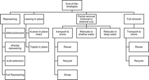
Following this categorization, a SWOT analysis (Kabak, Dağdeviren, and Burmaoğlu Citation2016) has been conducted on the various possibilities of end-of-life strategies to evaluate their strengths, weaknesses, opportunities, and threats (). Thus, the advantages and disadvantages of the suggested possibilities can be assessed, informed by current literature and experts’ opinions.
Table 1. SWOT analysis of end-of-life strategies
As outlined in , repowering, limited by the type of WT, improves the efficiency of energy production by means of a reduction in the maintenance and installation costs, and reuse of the existing structure. The output loss per year is estimated to be 1.6 ± 0.2% in wind farms (Staffell and Green Citation2014). Moreover, the existing foundation of the WT may not be suitable for a bigger WT with higher energy output. To counter this issue, the turbine may be retrofitted by using pins and drilling holes on the monopile, grout, and the transition piece (Seo et al. Citation2017). Although renewable energy is an infinite source, energy harvesting is limited by the end-of-life estimation for the equipment and, in the case of OWT farms, finding the most suitable location for optimum wind energy extraction. The sites selected previously for the OWFs have a better chance of being the optimum location for wind energy extraction; therefore, it is always reasonable to seek ways of utilizing the same location. Several important aspects need to be considered before making a decision regarding the reuse of the site, such as cost benefit analysis and other pertinent issues, which require further research to be conducted.
Total removal is an expensive process as compared to other end-of-life options, but it helps to restore marine traffic and fishing activity. Partial removal can be considered after repowering options are exhausted; it concentrates more on ecological benefits, such as habitat life, and presents several advantages over the repowering option. Further research needs to be conducted on developing appropriate selection criteria between partial removal and repowering. Moreover, consideration of the economic aspect for decision-making is only part of the decision-making process; it is important to consider other factors involved in the project, such as risks related to operating time, environmental impact, number of heavy lifts, specialized equipment (logistics), health and safety, and insurance. To the best of authors’ knowledge, currently there is no research comparing these factors with each other or assessing their impacts on the project.
Leaving in place is a controversial end-of-life scenario due to its legal implications and socio- environmental impact. It may not be suitable to be considered as an independent strategy, but it can be considered in conjunction with the condition of the structure, the possibility of modification to the structure, removal options, etc.
The use of flotation is recommended by applying buoyancy techniques (using flotation chambers or bags) to the foundation piece to reduce the need for heavy-lifting cranes during the removal of the foundation and towing to the shore (Smith and Lamont Citation2017).
Vessel availability is another challenge in this industry. Using the same vessels for installation and decommissioning incurs lower costs; however, the increasing demand for vessels in the OWT, as well as the oil & gas industry for installation or decommissioning activities, makes the availability of vessels a challenge. This is further worsened by the limited time of the year that the vessels can operate due to extreme weather conditions. Effective management of these resources is key to executing the installation/ decommissioning activities of OWTs successfully. One of the ways this can be done is to plan the decommissioning activities based on the capability of available vessels as well as shipbuilding capacity.
Variability of the removal legislation and guidelines in different countries significantly influences the planning for decommissioning. Lack of this guidance might be harmful for the environment as well. The increasing demand for decommissioning of OWFs in the coming years calls for bridging the research gap in this field and also highlights the important role of legislation in planning.
6. Development of a decision support framework for the selection of end-of-life strategies
Having reviewed the state of the art in end-of-life strategies and their associated influencing factors, a generic decision support framework is proposed to inform systematic planning for the most appropriate end-of-life strategy (). The proposed model helps to optimize the time of decision-making by taking into account available data for the residual life estimation of critical subsystems, including foundation, nacelle components, cables and substations, as well as factors of technology obsolescence and potential costs of maintenance during their potentially extended service life period, in comparison with energy production data.
Figure 2. Decision support framework
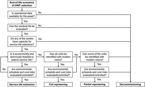
The process starts with the identification of available data for the assessment of the integrity of the wind farm as an asset. Absence of such data, or inability to estimate the residual life of the assets, limits the options of end-of-life strategies for decommissioning as no quantitative analysis can take place to quantify risks and benefits of alternative strategies.
The same stands for the case where an evaluation of the service life extension potential returns as an outcome a very short period of time that the asset’s life can be extended, which cannot justify extension. If it is economically and technically feasible to extend service life, continuing to use the assets through their standard operational management process, and after evaluation of environmental, schedule and cost risks, then service life extension should be chosen as the most appropriate option. If these risks cannot be evaluated and/or controlled, this should inform the techno-economic assessment and the strategies are then explored further. If this option is not economically or technically feasible, the options of full repowering should be explored, taking into consideration data related to the remaining life of the BOP, i.e. foundations and electrical systems, as this will stipulate the capacity of the repowered plant and will select the positions to be decommissioned, and hence the options of full or partial repowering. If related risks can be evaluated and controlled, these options qualify; if not, decommissioning should be selected as the preferred option.
The framework presented above, aims to structure the decisions of stakeholders, linking the top question with the basic options that are listed at the bottom. It is intended to stand as a high-level framework which should ultimately balance costs and risks through appropriate quantitative assessments. It should be noted that it is of great importance to involve internal and external stakeholders, organizational strategies as well as the applicable regulatory frameworks that could enable or make certain strategies more or less favorable. The proposed framework synthesizes findings from the literature following the critical review and its applicability range should be tested through subsequent application to a candidate wind farm; this task however falls outside the scope of this work and is suggested as the next step of this study.
6.1. Uncertainties on influencing factors
Providing accurate estimations for environmental, schedule and cost impacts plays a vital role in the selection of end-of-life strategies. Lack of data and experience, specifically from offshore wind energy assets, are the main limitations for an accurate estimation. Cost estimations published so far focus on certain cases and cannot be generalized to draw conclusions applicable to assets deployed in different conditions. Assumptions around factors such as cost of cable removals, monitoring of the seabed, increased maintenance requirements during the extended period can introduce significant uncertainty in the calculation of the updated life cycle costs. Availability of vessels imposes a further uncertainty on schedule and cost, the latter due to the limited fleet that can handle heavy lifting operations. Operational limits of vessels will also introduce schedule uncertainty. Finally, the requirement for restoration of the natural environment to its pre-deployment condition, introduces requirements such as weather and seabed condition monitoring and remedial actions that can impact both costs and the schedule.
7. Conclusion
Operators of a large number of wind farms are expected to reach the point of choosing an end-of-life strategy in the next few years, considering the large number of projects realized since the early 2000s. This study has critically reviewed the various end-of-life strategies for offshore wind farms, available technological options and finally the influencing factors that can inform such decisions. Different options have been qualitatively evaluated through a SWOT analysis and a decision support framework was compiled.
Based on the limited experience regarding the end-of-life scenarios of OWFs, it was suggested that the complexity of the environment as well as variety of the projects can be controlled by planning and implementation of the risk assessment methods (Liu, Liu, and Zhang Citation2014). It was found that repowering and partial removal are the two main choices. Full removal is also a feasible option; however, the cost of the method, as well as time requirements, are the major challenges associated with it.
This paper proposed a multi-attribute framework for supporting optimum decisions in terms of main constraints, such as the possibility of end-of-life strategies based on the special characteristics and influencing factors. This helps internal and external stakeholders to maximize the profitability of asset farms, while reducing those risks involved in the technological, safety, and environmental aspects, and to facilitate planning. In addition, the suggested framework can modify the optimized results of the decision-making in terms of available data for residual life estimation of critical subsystems. The implementation of energy production data in terms of any possibility of end-of-life strategies helps to challenge the potential costs of maintenance in the second decade of offshore life. It should be noted, that due to the limited experience in wind farms that have already reached the end of their nominal service life, further research on how such decisions could be better supported is required, e.g. through detailed integrity assessment frameworks, extended life cycle cost evaluation models, or further technological options.
Abbreviations
BOPBalance of Plant
CAPEXCapital Expenditure
CBMCondition Based Maintenance
CMCondition Monitoring
HSEHealth and Safety Executive
LCOELevelized Cost of Energy
NPVNet Present Value
O&MOperation and Maintenance
OPEXOperational Expenditure
OWTOffshore Wind Turbine
OWFOffshore Wind Farm
PSAPetroleum Safety Authority
ROVRemotely Operated Vehicle
SHMStructural Health Monitoring
SWOTStrengths, Weaknesses, Opportunities, Threats
UKCSUnited Kingdom Continental Shelf
Competing Interests
The authors declare no competing interests.
References
- Adedipe, O., F. Brennan, and A. Kolios. 2015. Corrosion fatigue crack growth in offshore wind monopile steel HAZ material. Analysis and Design of Marine Structures V. 207–12. CRC Press. doi:10.1201/b18179-29.
- Animah, I., and M. Shafiee. 2018. Condition assessment, remaining useful life prediction and life extension decision making for offshore oil and gas assets. Journal of Loss Prevention in the Process Industries. doi:10.1016/j.jlp.2017.04.030.
- Animah, I., M. Shafiee, and N. Simms. 2017. Techno-economic feasibility assessment of life extension decision for safety critical assets. Risk, Reliability and Safety: Innovating Theory and Practice. doi:10.1201/9781315374987-188.
- Beckman, R. C. 2012. Global Legal Regime on the Decommissioning of Offshore Installations and Structures. Martinus Nijhoff Publishers.
- Bezbradica, M., H. Kerkvliet, I. M. Borbolla, and P. Lehtimaki. 2016. “Introducing multi-criteria decision analysis for wind farm repowering: A case study on Gotland.” In 2016 International Conference Multidisciplinary Engineering Design Optimization (MEDO), 1–8. Belgrade, Serbia: IEEE. doi:10.1109/MEDO.2016.7746546.
- Brandt, H., S. Mohd Sarif, and D. N. Veritas. 2013. SPE 165882 Life Extension of Offshore Assets-Balancing Safety & Project Economics. SPE Asia Pacific Oil and Gas Conference and Exhibition, Jakarta, Indonesia, October 2013.
- Bull, A. S., and M. S. Love. 2019. Worldwide oil and gas platform decommissioning: A review of practices and reefing options. Ocean & Coastal Management. doi:10.1016/j.ocecoaman.2018.10.024.
- Castro-Santos, L., A. F. Vizoso, E. M. Camacho, and L. Piegiari. 2016. Costs and feasibility of repowering wind farms. Energy Sources, Part B: Economics, Planning, and Policy 11 (10):974–81. doi:10.1080/15567249.2014.907845.
- Cevasco, D., S. Koukoura, and A. J. Kolios. 2021. Reliability, availability, maintainability data review for the identification of trends in offshore wind energy applications. Renewable and Sustainable Energy Reviews 136 (February):110414. doi:10.1016/j.rser.2020.110414.
- Church, R. A. 2007. A Study of Living History : Deep WWII Shipwrecks in the Gulf of Mexico. PAST Foundation.
- Claisse, J. T., D. J. Pondella, M. Love, L. A. Zahn, C. M. Williams, and A. S. Bull. 2015. Impacts from partial removal of decommissioned oil and gas platforms on fish biomass and production on the remaining platform structure and surrounding shell mounds. PLoS ONE. doi:10.1371/journal.pone.0135812.
- Dalgic, Y., I. Lazakis, O. Turan, and S. Judah. 2015. Investigation of optimum jack-up vessel chartering strategy for offshore wind farm O&M activities. Ocean Engineering 95 (February):106–15. doi:10.1016/j.oceaneng.2014.12.011.
- Elliott, M., D. Burdon, K. L. Hemingway, and S. E. Apitz. 2007. Estuarine, coastal and marine ecosystem restoration: confusing management and science - A revision of concepts. Estuarine, Coastal and Shelf Science (3). doi:10.1016/j.ecss.2007.05.034.
- Esteban, M., J.-S. López-Gutiérrez, and V. Negro. 2019. Gravity-based foundations in the offshore wind sector. Journal of Marine Science and Engineering 7 (3):64. doi:10.3390/jmse7030064.
- Executive, Safety. Health and Safety Executive Health and Safety Executive Key Programme 4 (KP4) Ageing and Life Extension Programme Health and Safety Executive.
- Fowler, A. M., P. I. Macreadie, D. O. B. Jones, and D. J. Booth. 2014. A multi-criteria decision approach to decommissioning of offshore oil and gas infrastructure. Ocean & Coastal Management. doi:10.1016/j.ocecoaman.2013.10.019.
- Greater-Gabbard-Offshore-Winds-Limited. 2007. Decommissioning Programme, Greater Gabbard Offshore Wind Farm Project. 577000/403– MGT100– GGR – 107.
- Griffith, D. T., N. Yoder, B. Resor, J. White, J. Paquette, and P. Alistair, Valerie. 2012. Prognostic Control to Enhance Offshore Wind Turbine Operations and Maintenance Strategies. Copenhagen, Denmark.
- Halvorsen-Weare, E. E., C. Gundegjerde, I. B. Halvorsen, L. M. Hvattum, and L. M. Nonås. 2013. Vessel fleet analysis for maintenance operations at offshore wind farms. Energy Procedia 35:167–76. doi:10.1016/j.egypro.2013.07.170.
- He, W., R. J. Grant, V. Baden, and J. Suntharalingam. 2020. Innovative alternatives for repowering offshore wind farms. Journal of Physics. Conference Series 1618 (September):042037. doi:10.1088/1742-6596/1618/4/042037.
- Hinzmann, N., P. Stein, and J. Gattermann. 2018. “Decommissioning of offshore monopiles, occuring problems and alternative solutions.” In Volume 9: Offshore Geotechnics; Honoring Symposium for Professor Bernard Molin on Marine and Offshore Hydrodynamics. American Society of Mechanical Engineers. Madrid, Spain. doi:10.1115/OMAE2018-78577.
- Hinzmann, N., P. Stein, J. Gattermann, J. Bachmann, and G. Duff. 2017. Measurements of Hydro Sound Emissions during Internal Jet Cut- Ting during Monopile Decommissioning 1 Preface. February 2018.
- Hokstad, P., S. Håbrekke, R. Johnsen, and S. Sangesland. 2010. SINTEF A15322-Unrestricted Ageing and Life Extension for Offshore Facilities in General and for Specific Systems. Norway: SINTEF Technology and Society.
- Hou, P., H. Weihao, M. Soltani, B. Zhang, and Z. Chen. 2016. “Optimization of decommission strategy for offshore wind farms.” IEEE Power and Energy Society General Meeting 2016-Novem, IEEE, 1–5. doi:10.1109/PESGM.2016.7741634.
- Hou, P., P. Enevoldsen, H. Weihao, C. Chen, and Z. Chen. 2017. Offshore wind farm repowering optimization. Applied Energy 208 (December):834–44. doi:10.1016/j.apenergy.2017.09.064.
- HSE. 2009. Health and Safety Executive A Report by the Offshore Division of HSE’s Hazardous Installations Directorate Key Programme 3-Asset Integrity.
- Ioannou, A., A. Angus, and F. Brennan. 2018. A lifecycle techno-economic model of offshore wind energy for different entry and exit instances. Applied Energy 221C:406–24. doi:10.1016/j.apenergy.2018.03.143.
- Ioannou, A., A. Angus, and F. Brennan. 2018a. Parametric CAPEX, OPEX, and LCOE expressions for offshore wind farms based on global deployment parameters. Energy Sources, Part B: Economics, Planning, and Policy 13 (5):281–90. doi:10.1080/15567249.2018.1461150.
- Ioannou, A., A. Angus, and F. Brennan. 2018b. A lifecycle techno-economic model of offshore wind energy for different entry and exit instances. Applied Energy 221 (July):406–24. doi:10.1016/j.apenergy.2018.03.143.
- Ioannou, A., A. Angus, and F. Brennan. 2019. Informing parametric risk control policies for operational uncertainties of offshore wind energy assets. Ocean Engineering 177 (April):1–11. doi:10.1016/j.oceaneng.2019.02.058.
- Jadali, A., A. Ioannou, K. Salonitis, and A. Kolios. 2021. Decommissioning vs repowering of offshore wind farms – A techno-economic assessment. International Journal of Advanced Manufacturing Technology. (9–10). doi:10.1007/s00170-020-06349-9.
- Januário, C., S. Semino, and M. Bell. 2007. “Offshore windfarm decommissioning : A proposal for guidelines to be included in the European maritime policy.” European Wind Energy Conference, July, 1–10. Boston, MA, USA.
- Jardine, R. J., J. R. Standing, and F. C. Chow. 2006. Some observations of the effects of time on the capacity of piles driven in sand. Géotechnique 56 (4):227–44. doi:10.1680/geot.2006.56.4.227.
- Kabak, M., M. Dağdeviren, and B. Serhat. 2016. A hybrid SWOT-FANP model for energy policy making in Turkey. Energy Sources, Part B: Economics, Planning, and Policy 11 (6):487–95. doi:10.1080/15567249.2012.673692.
- Kaiser, M. J. 2015. Decommissioning forecast in the deepwater Gulf of Mexico, 2013-2033. Marine Structures. doi:10.1016/j.marstruc.2014.12.006.
- Kaiser, M. J., and B. Snyder. 2010. Offshore Wind Energy Installation and Decommissioning Cost Estimation in the U.S. Outer Continental Shelf. November, Herndon, VA. TA&R study 648. 340 pp.
- Kaiser, M. J., and B. Snyder. 2012. Offshore wind decommissioning regulations and workflows in the Outer Continental Shelf United States. Marine Policy 36 (1):113–21. doi:10.1016/j.marpol.2011.04.004.
- Kaiser, M. J., and M. Liu. 2014. Decommissioning cost estimation in the deepwater U.S. Gulf of Mexico - fixed platformsand compliant towers. Marine Structures. doi:10.1016/j.marstruc.2014.02.004.
- Kerkvliet, H., and H. Polatidis. 2016. Offshore wind farms’ decommissioning: A semi quantitative multi-criteria decision aid framework. Sustainable Energy Technologies and Assessments. doi:10.1016/j.seta.2016.09.008.
- Kolios, A., and U. Smolka. 2020. “Risk-based maintenance strategies for offshore wind energy assets.” In 2020 Annual Reliability and Maintainability Symposium (RAMS), 1–6. Palm Springs, CA, USA: IEEE. doi:10.1109/RAMS48030.2020.9153642.
- Kolios, A. J., A. Rodriguez-Tsouroukdissian, and K. Salonitis. 2014. Multi-Criteria Decision Analysis of Offshore Wind Turbines Support Structures under Stochastic Inputs. In Ships and Offshore Structures. no. ahead-of-print. Taylor & Francis. 1–12.
- Kolios, A. J., and M. Martinez Luengo. 2016. Operational management of offshore energy assets. Journal of Physics. Conference Series 687 (1). doi: 10.1088/1742-6596/687/1/012001.
- Lantz, E., M. Leventhal, and I. Baring-Gould. 2013. Wind Power Project Repowering: Financial Feasibility, Decision Drivers, and Supply Chain Effects. National Renewable Energy Laboratory Publisher location:
- Liu, D. D., S. L. Liu, and J. H. Zhang. 2014. Visualization analysis of research hotspots based on citespace II: taking medical devices as an example. Medical Devices: Evidence and Research. doi:10.2147/MDER.S69685.
- Luengo, M., and A. Kolios. 2015. Failure mode identification and end of life scenarios of offshore wind turbines: A review. Energies 8 (8):8339–54. doi:10.3390/en8088339.
- Manago, F., and B. Williamson. 1997. Decommissioning and Removal of Oil and Gas Facilities Offshore California: Recent Experiences and Future Deepwater Challenges. Santa Barbara Santa Barbara, CA, USA: Southern California Educational Initiative, Coastal Research Center, Marine Science Institute, University of California.
- Martin, H., G. Spano, J. F. Küster, M. Collu, and A. J. Kolios. 2013. Application and extension of the TOPSIS method for the assessment of floating offshore wind turbine support structures. Ships and Offshore Structures 8 (5). doi: 10.1080/17445302.2012.718957.
- Martínez, E., J. I. Latorre-Biel, E. Jiménez, F. Sanz, and J. Blanco. 2018. Life cycle assessment of a wind farm repowering process. Renewable and Sustainable Energy Reviews. 93: 260–71. Elsevier Ltd. doi:10.1016/j.rser.2018.05.044.
- Martinez-Luengo, M., A. Kolios, and L. Wang. 2016. Structural health monitoring of offshore wind turbines: A review through the statistical pattern recognition paradigm. Renewable and Sustainable Energy Reviews 64. doi:10.1016/j.rser.2016.05.085.
- Martinez-Luengo, M., P. Causon, A. B., and A. J. Kolios. 2017. “The effect of marine growth dynamics in offshore wind turbine support structures.” In Progress in the Analysis and Design of Marine Structures - Proceedings of the 6th International Conference on Marine Structures, MARSTRUCT 2017. doi:10.1201/9781315157368-100.
- Matutano, C., V. Negro, J.-S. López-Gutiérrez, and M. Dolores Esteban. 2013. Scour prediction and scour protections in offshore wind farms. Renewable Energy 57 (September):358–65. doi:10.1016/j.renene.2013.01.048.
- Miñambres, O. Y., and J. U. Garcia. 2020. Assessment of Current Offshore Wind Support Structures Concepts-Challenges and Technological Requirements by 2020. Germany: Karlshochschule International University.:
- Ortegon, K., L. F. Nies, and J. W. Sutherland. 2013. Preparing for end of service life of wind turbines. Journal of Cleaner Production. doi:10.1016/j.jclepro.2012.08.022.
- Palkar, S., and T. Markeset. 2012. Extending the service life span of ageing oil and gas Offshore Production Facilities. IFIP Advances in Information and Communication Technology. doi:10.1007/978-3-642-33980-6_25.
- Petersen, J. K., and T. Malm. 2006. Offshore windmill farms: threats to or possibilities for the marine environment. Ambio. (2). SpringerRoyal Swedish Academy of Sciences. doi: 10.2307/4315689.
- Plodpradit, P., O. Kwon, V. N. Dinh, J. Murphy, and K.-D. Kim. 2020. Suction bucket pile–soil–structure interactions of offshore wind turbine jacket foundations using coupled dynamic analysis. Journal of Marine Science and Engineering 8 (6):416. doi:10.3390/jmse8060416.
- Safaei, F., N. Tazi, E. Chatelet, and Y. Bouzidi. 2019. “Optimal topology and repowering time for offshore wind turbines.” In 2019 6th International Conference on Control, Decision and Information Technologies (CoDIT), 1344–49. Paris, France: IEEE. doi:10.1109/CoDIT.2019.8820519.
- Scheu, M. N., A. Kolios, T. Fischer, and F. Brennan. 2017. Influence of statistical uncertainty of component reliability estimations on offshore wind farm availability. Reliability Engineering and System Safety 168. doi:10.1016/j.ress.2017.05.021.
- Scheu, M. N., L. Tremps, U. Smolka, A. Kolios, and F. Brennan. 2019. A systematic failure mode effects and criticality analysis for offshore wind turbine systems towards integrated condition based maintenance strategies. Ocean Engineering 176. doi:10.1016/j.oceaneng.2019.02.048.
- Scira Offshore Energy. 2014. Decommissioning Programme - Sheringham Shoal. Statoil.
- Seo, J., W. Schaffer, M. Head, and M. Shokouhian. 2017. Retrofitting of Monopile Transition Piece for Offshore Wind Turbines. The 27th International Ocean and Polar Engineering Conference, 25-30 June, San Francisco, California, USA.
- Shafiee, M., F. Brennan, and I. A. Espinosa. 2016. A parametric whole life cost model for offshore wind farms. The International Journal of Life Cycle Assessment. (7). doi:10.1007/s11367-016-1075-z.
- Shafiee, M., and I. Animah. 2017. Life extension decision making of safety critical systems: an overview. Journal of Loss Prevention in the Process Industries. doi:10.1016/j.jlp.2017.03.008.
- Smith, G., C. Garrett, and G. Gibberd. 2015. Logistics and cost reduction of decommissioning offshore wind farms.EWEA Offshore 2015. (March).
- Smith, G., D. Michael, R. Paul, W. Arlene, G. Chris, H. John, F. Dariush, and E. Chris. 2016. Assessment of offshore wind farm decommissioning requirements.Ontario Ministry of the Environment and Climate Change. (May).
- Smith, G., and G. Lamont. 2017. Decommissioning of offshore wind installations - what we can learn - what we can learn. Offshore Wind Energy 2017. June 2017.
- Smyth, K., N. Christie, J. P. Daryl Burdon, R. B. Atkins, and M. Elliott. 2015. Renewables-to-reefs? - decommissioning options for the offshore wind power industry. Marine Pollution Bulletin 90 (1–2):247–58. doi:10.1016/j.marpolbul.2014.10.045.
- Staffell, I., and R. Green. 2014. How does wind farm performance decline with age?. Renewable Energy 66 (June):775–86. doi:10.1016/j.renene.2013.10.041.
- Sultan, A., A. Mohamed, P. T. Mativenga, and E. Lou. 2018. Managing supply chain complexity: foresight for wind turbine composite waste. Procedia CIRP. 69: 938–43. Elsevier B.V. doi:10.1016/j.procir.2017.11.027.
- Sun, H., X. Gao, and H. Yang. 2019. Investigation into offshore wind farm repowering optimization in Hong Kong. International Journal of Low-Carbon Technologies 14 (2):302–11. doi:10.1093/ijlct/ctz016.
- Tao, Y., Y. Wen-xia, L. Guan-he, Y. Dong, W. Hua-jie, and Y. Yan. 2000. Marine biofouling in Offshore Areas South of Hainan Island, Northern South China Sea. Chinese Journal of Oceanology and Limnology (2). doi:10.1007/bf02842572.
- Topham, E., D. McMillan, S. Bradley, and E. Hart. 2019b. Recycling offshore wind farms at decommissioning stage. Energy Policy. doi:10.1016/j.enpol.2019.01.072.
- Topham, E., E. Gonzalez, D. McMillan, and J. Elsa. 2019a. Challenges of decommissioning offshore wind farms: overview of the European experience. Journal of Physics. Conference Series 1222 (May):012035. doi:10.1088/1742-6596/1222/1/012035.
- Topham, E., and M. David. 2017. Sustainable decommissioning of an offshore wind farm. Renewable Energy 102 (March):470–80. doi:10.1016/j.renene.2016.10.066.
- Transmission Capital. 2013. TC Ormonde OFTO Ltd Decommissioning Programme ORM\TEC\002-2 BD\ORM\TEC\002 2.
- Ziegler, L., N. Cosack, A. Kolios, and M. Muskulus. 2019. Structural monitoring for lifetime extension of offshore wind monopiles: verification of strain-based load extrapolation algorithm. Marine Structures 66 (July):154–63. doi:10.1016/j.marstruc.2019.04.003.
- Zintzen, V., C. Massin, A. Norro, and J. Mallefet. 2006. Epifaunal inventory of two shipwrecks from the Belgian Continental shelf. Hydrobiologia 555 (1):207–19. doi:10.1007/s10750-005-1117-1.
- Zuo, T., Y. Zhang, K. Meng, Z. Tong, Z. Y. Dong, and Y. Fu. 2021. Collector system topology design for offshore wind farm’s repowering and expansion. IEEE Transactions on Sustainable Energy 12 (2):847–59. doi:10.1109/TSTE.2020.3022508.