
ABSTRACT
The paper intends to provide a building assessment methodology for the conservation planning of concrete buildings, presenting the demonstrative case-study of the Ocean Swimming Pool (design 1960–1966; conservation 2018–2021) conceived by the Pritzker Prize Álvaro Siza, in Portugal. The building is a landmark of 20th century architecture in the national and international context, being listed as National Monument and included in the World Heritage Tentative List. The article will focus particularly on the building assessment methodology, supported by the cross-analysis of the ‘documentary evidence’ and ‘physical evidence’, allowing for an integrated approach for conservation planning. The paper includes documentation on the building chronology and construction, as well as on the inspection and diagnosis using both non-destructive and minor destructive testing. Moreover, the article presents a pilot demonstration of concrete repair supported on the building knowledge and diagnosis. This real case study shows the advantages of integrating conservation criteria and methods used for traditional buildings to modern heritage in concrete (going beyond the common visible patch repair), in which there are still few case-studies illustrating good practices. This holistic approach has also contributed to the development of detailed policies for risk assessment, concrete conservation and maintenance in the framework of the Conservation Plan.
1. Introduction
In the present-day context of vulnerability at a global scale, conservation planning is a key strategy for a more sustainable management of resources, shifting from a reactive and interventionist approach (post-damage) to preventive conservation (pre-damage) and continued care over time (Ferreira Citation2018; Ramos et al. Citation2018). Hence, integrated methodologies for built heritage preventive-planned conservation (Vandesande, Verstrynge, and Van Balen Citation2020) must be developed when implementing management and conservation plans, as the following demonstration in the present article.
The Ocean Swimming Pool in Leça da Palmeira was designed by the renowned Portuguese architect Álvaro Siza between 1960 and 1966 (the construction site was concluded in 1973), for the seaside town of Leça da Palmeira, in the north of Porto. In this early work of his career, Siza adopted an expressively modern technology and abstract language, building a succession of walls in reinforced concrete over the seaside rocks, which were harmoniously integrated with the interior timber structure of the changing rooms. This work has been considered a masterpiece because of its modernity and organic integration into the existing site and landscape. The building is listed as a National Monument (since 2011) and has been included in the “Ensemble of Alvaro Siza Architectural Works in Portugal” included in the Tentative List for the World Heritage in 2017.
However, this building has been at risk for many years because of its maritime location and the nearby oil refinery, which have aggravated the decay of its concrete structures by triggering corrosion of steel reinforcement. Due to its vulnerable location, the Ocean Swimming Pool constitutes an important case study, which requires a precise long-term Conservation Management Plan which is being prepared under the ‘Keeping it Modern’ grant funded by the Getty Foundation.
The main contribution of this paper is to put into perspective the sustained process of planned conservation through an integrated methodology, as well as its application to a pilot demonstration site of concrete conservation. In this way, the case presented in this paper is a valuable resource both for research and for the professional field, and the proposed model may therefore help in identifying possible paths for conservation planning of buildings in exposed concrete.
2. Methodology
The methodology for Conservation Planning advocated by the Getty Conservation Institute (Macdonald Citation2022, 27) is supported on a value-based approach and follows the Burra Charter process (ICOMOS Australia Citation2013, 10) structured in six stages: i) Understanding the Place; ii) Assessing Significance; iv) Gather information to inform Policies; v) Develop Policies to Conserve and Sustain Significance; vi) Implement and Monitor the CMP. The building assessment methodology presented in this paper informs all stages of the process, gathering both the ‘documentary evidence’ and ‘physical evidence’ on the site (Kerr Citation2013, 4), see .
Figure 1. Building assessment methodology.
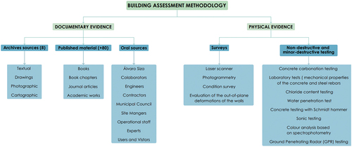
For the Ocean Swimming Pool, ‘documentary evidence’ included different kind of sources from eight archives (written, graphic, photographic, cartographic materials, etc.), published material (more than eighty publications, including books, chapters, articles and academic works), oral sources (interviews to different stakeholders), among others. In order to assess the cultural significance of the site several participation strategies were carried out, namely: i) interviews and surveys (building actors-architect, engineer, contractor, owner, site managers, Municipal Council); ii) social media; iii) workshops (children, students, experts); and iv) other activities (exhibition, visits, documentary film). The cross-analysis of these sources made it possible, even over half a century later, to assess the material history of the building, namely its construction phases and the building materials and technologies applied in its design and construction.
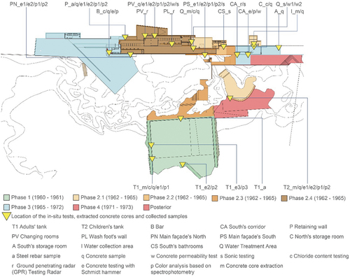
Using the building fabric as the most reliable source (Kerr Citation2013, 7), the analysis of the ‘physical evidence’ was also of major importance in the process, supported on a geometric survey (laser scanner and photogrammetry, allowing for for 3D BIM modelling), building condition assessment using non-destructive and minor destructive testing, see . Hence, a laser scanner survey and photogrammetric processing of elevations were carried out, while inspection and diagnosis included condition survey, evaluation of the out-of-plane deformations of the walls, and non-destructive and minor-destructive testing. The testing campaign included: i) concrete carbonation testing; ii) laboratory tests to determine the mechanical properties of the concrete and steel rebars; iii) chloride content testing; iv) water penetration testing; v) concrete testing with Schmidt hammer; vi) sonic testing; vii) colour analysis based on spectrophotometry; viii) Ground Penetrating Radar (GPR) testing.
These tests allowed to perform a pilot demonstration of concrete repair following the criteria of minimum intervention and compatibility as defined in international recommendations for built heritage conservation (ISCARSAH, Citation2003; ISC20c, Citation2017) as well as the specific guidelines for concrete conservation (Harboe, G. et al, Citation2021; Macdonald and Gonçalves Citation2020). Also, it intends to go beyond the traditional patch repair in contrast with the existing surface which as demonstrated to be less compatible in aesthetical and technical terms (Croft and Macdonald Citation2019, 15).
The documentary and physical evidence contributed to the characterization of the building in detail and are the basis for the future definition of conservation and maintenance policies, in the framework of the Conservation Plan developed under the Keeping It Modern Grant awarded by the Getty Foundation for this building.
3. Ocean Swimming Pool: construction phases and building technologies
3.1. Context
The Ocean Swimming Pool (also known as “Tidal Swimming Pool”), is located in Leça da Palmeira, in the north of the city of Matosinhos. In the mid-twentieth century, the mayor Fernando Pinto de Oliveira (1911–1975) envisaged an ambitious plan for the redevelopment and requalification of this seaside area, with the aim of recovering its potential as a tourism and leisure destination..
The Ocean Swimming Pool is one of Alvaro Siza’s most internationally recognized works, marking a turning point in his career by expressing a tectonic shift from regionalist inspiration towards modern construction technologies and materials (Ferreira and Fernandes Citation2021). As one of the first architectural works in exposed concrete in Portugal, the building is also considered a masterpiece of integration between engineering and architecture, both for the technical aspects underpinning the functioning of the swimming pools and for its modern tectonics of brutalist expression, deploying raw materials such as exposed concrete, copper and oil-darkened Riga wood.
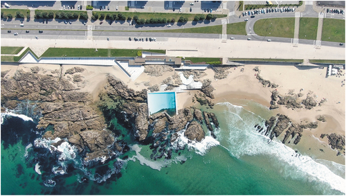
The building has been in operation for more than fifty years since its public opening in 1965. Serving as leisure area and meeting place for both local people and visitors, the pool has become a social and cultural landmark for the community, playing an essential role in their identity and collective memory, see .
Figure 2. Aerial view of the Ocean Swimming Pool (credits: Pixel).
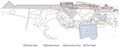
Recent conservation and extension interventions designed by Álvaro Siza (2018–2021) represent an exceptional case of an original architect preserving his own work and enhancing the site’s significance by respecting its design principles, both in the conservation of pre-existing features and in a new extension to the building. shows a plan with the different functions of the whole complex, with two swimming pools (adults and children), platforms of terrace/solarium, changing rooms and other facilities.
Figure 3. Plan of the Ocean Swimming Pool — Plan of the Ocean Swimming Pool — (1) adults’ swimming pool; (2) children’s swimming pool; (3) entrance ramp; (4) men’s changing rooms; (5); women’s changing rooms; (6) reception; (7) changing rooms hallway; (8) collective changing room; (9) chlorine cabinet; (10) water treatment area; (11) south bathrooms; (12) swimming pools pathways and solarium; (13) south platform; (14) bar; (15) bar’s kitchen; (16) bar’s terrace; (17) security guard’s room; (18) south storage rooms; (19) water collection area; (20) swimming pools’ platform; (21) north platform; (22) north bathrooms; (23) staff’s changing rooms and bathrooms; (24) north storage room; (25) trash storage room.
3.2. Construction phases
3.2.1. Original design (1960-1973)
In November 1959, the Matosinhos Municipal Council commissioned Ribeiro da Silva Lda., a construction company specialized in maritime construction works, to study the feasibility of building a tidal swimming pool at the Leça da Palmeira beach and including the respective budget. The design was commissioned to the engineer Bernardo Ferrão, the co-owner of the construction company, who has suggested to the Muncipal Council to include an architect in the team. Álvaro Siza was thus invited to design the swimming pools and supporting facilities [probably due to the fact that, at that time, he was working for Ferrão’s brother, Fernando Távora.]
Contrary to what is the popular belief, the Ocean Swimming Pool complex, designed and built between 1960 and 2021, was not conceived as a single project but rather resulted from multiple commissions and revisions made by the public entities, that dictated the growth of the bathing complex (Ferreira and Urbano Citation2022). In regard to the original design, four main phases are identified (Ganshirt Citation2004) which construction site was concluded in 1973 (see ).
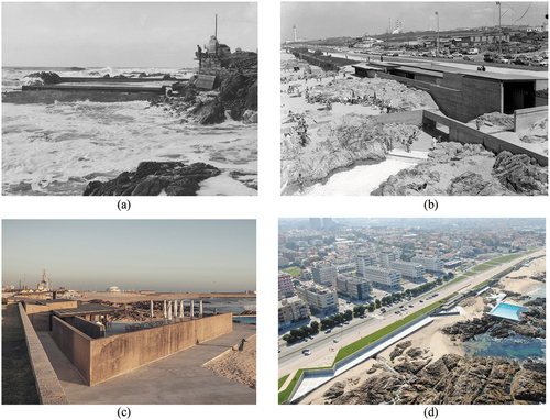
Figure 4. Álvaro Siza, Ocean Swimming Pool design phases: a) Phase 1 (1960–1961) adults’ swimming pool; b) Phase 2 (1962–1965) children’s swimming pool, water treatment facilities, bathrooms and changing rooms; c) Provisional structures to be demolished (1966) bar and bathrooms; d) Phase 3 (1970–1972) north and south platforms, storage rooms, bar and terrace; e) Restaurant (unbuilt).
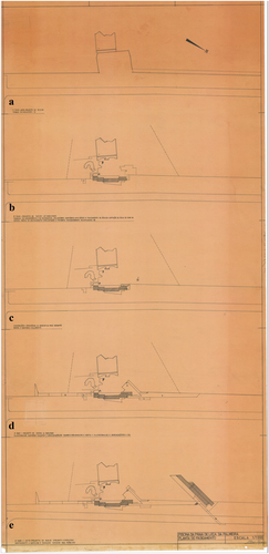
Figure 5. a) Beginning of the construction works in 1961 (first phase); b) Changing room’s building as of 1968 (second phase); c) North extension of the bar (third/fourth phases); d) Recent conservation and extension to the north (2018–2021).
The first design phase (1960–1961) was presented on 1960 by engineer Ferrão relating to a single tidal pool for adults, made of cyclopean concrete [composed of large stones sourced on the site and mixed with a 300 kg per m3 cement concrete] walls embedded in the rocks. In this initial design, the pool coexisted with the ‘Meia Laranja’ [‘Half-orange’] platform — an extension of the seafront avenue, which was afterwards removed to create an area that would function as a solarium.
The second phase (1962–1965) of construction was divided into four parts. First, a second swimming pool for children was built, featuring a round wall, as well as an area for the collection and treatment of the water, including the network of pipes that connected this to the swimming pools (1). Subsequently, the bathroom facilities were added at the southern end (2), followed by the construction of walkways providing access to the swimming pools (3). The final part consisted of building the changing rooms, as well as the access ramp and the retaining walls that connect the building to the seafront avenue (4). A temporary bar was also installed, while the definitive one was still being designed. This design phase envisaged the construction of a restaurant over the rocks at the northern side of the complex, which as never built (5).
In 1966, Siza presented the design for the third phase (1966–1973) of the project, as well as a preliminary study of a restaurant, to the north of the swimming pools. This phase was, however, postponed until 1970, as it needed to be revised in order to comply with the new health and safety requirements. This phase regarded the construction of the definitive bar, which features a triangular terrace with a 45° angled wall. The building was extended to the north, with a solarium, bathrooms and storage area, as well to the south, with the security guard’s room, a storage area and a ramp connecting the seafront avenue to the beach.
Finally, a small fourth phase was completed in 1973 regarding the addition of the bar’s curved counter, the platform adjacent to the children’s pool with a ramp that accesses to the beach and the south end platform with a 45° oriented double stair.
For the first and second phases, the contractor was a small local firm, Ribeiro da Silva, Lda. (later purchased by a larger company, Mota Engil, Lda.), owned by engineer Ferrão (1913–1982), who designed all of the building’s structures and infrastructures, while the third and fourth phases (1965–73) were the work of the firm Enobra.
shows the comparison of the design phases (1960–1965) according to Álvaro Siza (Siza and Ferrão Citation1967). shows a complementary photographic chronology of the evolution of the building complex, even before its construction and until recent conservation and extension.
3.2.2. Recent interventions (1995-2021)
The maritime setting and consequent exposure of the building caused deterioration to the concrete structures in the 1980s and 1990s. Conservation works took place in 1995, when the roofs were replaced and certain areas of exposed concrete were repaired with the application of a new 4 cm thick concrete cover.
From 2018–2021, Álvaro Siza developed a new intervention project including the replacement of the swimming pools’ technical installations and infrastructures (namely the hydraulic and water treatment installations, which were obsolete in 2018), the conservation of the existing buildings and the reconstruction of the north side building in order to respond to current regulations (bathroom for disabled, waste treatment area, separate bathrooms for the public and the bar dependents). Recent intervention also included the extension of the solarium platform further north with a triangular boundary (where, in the original project, Siza had envisaged the restaurant over the rocks). With this gesture, while preserving his own work, the architect has definitively completed the design of the building complex enhancing its significance for future generations.
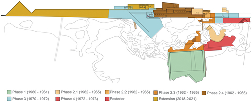
provides a 3D modelling over a laser scanner point cloud of all building phases, while presents the constructive phases as built.
Figure 6. Laser scanner survey and 3D modelling of the building after recent conservation and extension (2018–2021).
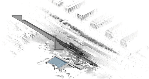
Figure 7. Synthesis of the construction phases — as built (1960–2021).
3.3. Building materials and techniques
The Ocean Swimming Pooling was built with few materials and techniques: assembled copper coverings, reinforced concrete, and wooden structures and joinery. The swimming pool tanks and buildings were mainly constructed in good-quality concrete, with a very small amount of reinforced steel.
In regard to the concrete used in the building site there were different compositions: i) the cyclopean concrete walls were composed of granite stones, sourced from the site, mixed with a 300 kg per m3 cement concrete; ii) the foundation, the platforms pavements and the bar’s triangular terrace is made out of concrete with 250 kg cement per m3; iii) the concrete walls are reinforced with 10 kg of steel per m3 in the retaining walls and 15 kg/m3 in the remaining walls; iv) the concrete roof slabs in the North and South roof gardens have 52 kg/m3 and 130 kg/m3 of steel, respectively; v) in the North area, the slab also has a concrete beam (which extends to the retaining wall shown below in ) that is reinforced with 190 kg/m3 of steel (Mota Citation1972).
The roofs in the changing rooms and annexes consist of a single sloping structure made of dark Riga wood, which was recovered and reused from previous constructions, covered with copper sheets placed on top of asphalt screens. This wood was treated with linseed oil and fixed in place with galvanised fittings.
The buildings at the northern and southern ends have reinforced concrete slabs. Most of the pavement areas consist of prefabricated concrete plates. Specific information is provided next on concrete walls and slabs which were, because of the damages they presented, the main focus of the inspection and diagnosis developed for the Ocean Swimming Pool.
3.3.1. Concrete slabs
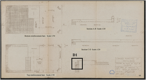
The roof slabs were built without any interruption (to avoid construction joints) and the concrete was compacted, using a Wacker internal vibrator. The slabs were designed simply supported to avoid cracking in the lightly reinforced walls due to bending and thermal expansion of the slab, with a joint at the wall top including a tooth detail (D1) to avoid water ingress, see . The slabs were waterproofed with prefabricated plastic-asphalt screens (Morterplas), using a polyethylene film cover on both sides and special catalytic asphalt layers. These were applied directly using regular welded overlaps of 10 cm. These screens reached all the way up to the roof plateau, with a double layer at the edges, where they were welded. Finally, protection was applied in the form of screed (1:3, cement and sand, with 3 cm thickness and a trowel finish; Mota Citation1972).
Figure 8. Bernardo Ferrão, Slab for the water treatment area, 1965 (Matosinhos Municipal Council Archive).
3.3.2. Concrete walls
The retaining walls at the northern and southern ends of the site were built in cyclopean concrete, with the stones being manually arranged, cleaned and watered following the knowledge developed in the past by the designer (Ferrão Citation1945), see . A plaster made of cement and sand was applied to the back of the walls, with 0.588 litres of Febproof, a waterproofer and plasticizer, being used in the manufacture for each 50 kg of cement, making it waterproof and compact.
Figure 9. Bernardo Ferrão, Retaining walls, 1966 (Matosinhos Municipal Council Archive).
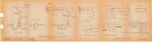
Figure 10. Photographs during construction, 1971 (Mota Citation1972; Centro de Documentação da FAUP).
The exposed concrete walls required a careful execution of the formwork in order to define horizontal lines. The formwork was made of pinewood, which could be reused later due to its thickness (4 cm) and the application of oil. The walls were poorly reinforced, with a 5 mm-thick mesh, consisting of a grid of 15 × 15 cm. Ties were placed to connected the side walls of the formwork. The shoring was made using (15 cm) pine posts and foundations. All the expansion joints were made of Meyco rubber. As stated, the slabs were separated from the walls in order to provide an improved structural behaviour (Ferreira, Fernandes, and Barosa Citation2021).
4. Inspection and diagnosis
The inspection and diagnosis were aimed at surveying the damage, estimating the material and geometric properties and identifying the material degradation mechanisms. This task involved visual inspection, scanning of the structure with laser scanner and drone, as well as in-situ non-destructive and minor destructive tests and laboratory tests of samples extracted from the structure (concrete, cement paste, steel rebars and timber). The in-situ tests and the samples were done and collected, respectively, in parts of the structure built in different construction phases (). Next, the main works and results of the inspection and diagnosis are presented.
Figure 11. Locations of the in-situ tests and the extracted samples.
4.1. Condition survey
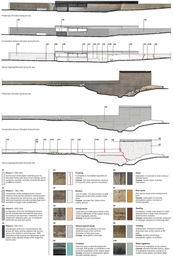
The visual inspection allowed to verify that the building is in a reasonable state of conservation, without interventions that have substantially altered its original form (). However, the building has been at risk because of its maritime location and the nearby oil refinery, which together have aggravated the decay of the concrete, by triggering cracking, corrosion and spalling of its steel reinforcement. While the carbon dioxide from the refinery accelerates the carbonation process, the chlorides of the salt water and salt fog penetrate the concrete and cause reinforcement corrosion, which consequently causes the cracking and spalling of the concrete. Furthermore, repair campaigns conducted by the Matosinhos Municipal Council since the 1980s have led to problems such as delamination, pattern cracking and staining.
Figure 12. Condition survey mapping.
While the building and pools are mainly constructed with a small amount of reinforced steel, the beams and slabs have thicker reinforced steel bars, and it is here that the main problems of reinforcing steel corrosion, and subsequent spalling, have been observed. Spalling also occasionally occurs at the top of the walls or in the swimming pool tanks, namely at the points where the tanks connect with the rocks.
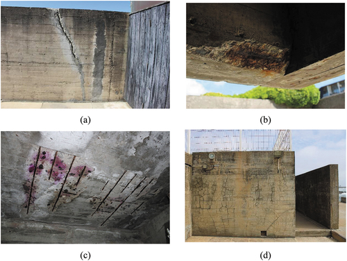
The most evident signs of deterioration in the concrete walls are in the form of cracks, creating visible discontinuities in the surface of the material. Most of these cracks are not apparently related to steel corrosion. The vertical cracks in the longitudinal walls seem to be caused by the absence of movement joints in the original design, which corresponds to a damage over time possibly due to shrinkage and/or thermal movements. These were worsened by interventions performed by the Municipal Council, namely the filling of the cracks with incompatible mortar (Portland cement mortar with limited compatibility, reversibility or aesthetic integration concerns) (). Moreover, some concrete surfaces have small red/brown stains created by the oxidation of rusted metal inside the concrete, which has deposited on the surface. In some beams, there are signs of a loss of material (spalling), caused by the corrosion of reinforced steel rebars (). The bottom surface of the slab of the South’s storage room was severely affected by the corrosion of the rebars (). There is also damage associated with distributed cracking (taking the form of a polygonal net, similar to a spider’s web) caused by the addition, in the 1980s, of a 4 cm concrete layer (with light mesh) over some walls, because of incompatibility with the pre-existing concrete walls or shrinkage ().
Figure 13. Examples of damage: (a) cracks and repair with the application of mortar; (b) spalling caused by reinforced steel corrosion in a beam; (c) distributed crack pattern; (d) concrete slab severely affected by the corrosion of the reinforced steel.
Some of the walls show signs of efflorescence in the form of a textured white stain, which is caused by the infiltration of water in the concrete. The building also suffers from localized spots displaying a chromatic change, caused by the rainwater running off the surface and leaving a deposit. There are also the effects of biological colonization growing on the concrete surface, which changes its texture and colour.
The copper surface of the building’s roofs has a green colour due to oxidation and leakage has been identified in the assembly of the copper elements, resulting from the exposure and lack of maintenance. The timber structure of the roof and the changing rooms’ partition walls presents localized detachment of the coating and an oily texture, which results from the excessive amounts of linseed oil used in its maintenance. The screws used for the timber structure show signs of oxidation, with brown textured spots on their surface. The adults’ tank presents spots and biological colonization.
The out-of-plane deformation of the retaining wall and the main façade’s North and South walls were evaluated, based on the laser scanner survey. It was concluded that the highest out-of-plane deformation is equal to 34 mm and is located in the main façade’s North wall. Some of this deformation is seemingly not due to the original execution and is partly associated with foundation movement.
Finally, the most notable deficiency in the building’s use is related to the hydraulic infrastructure, as many of the pipes of the water system have either been destroyed by corrosion or are clogged with sand, which means that they were compromising the pools’ functionality (the pools were closed to the public in 2018 and have reopened in 2021).
4.2. Non-destructive and laboratory testing
4.2.1. Concrete properties testing
In the evaluation of the properties of the concrete, several non-destructive and minor-destructive tests were carried out, namely: (1) in-situ concrete carbonation tests; (2) laboratory tests to determine the mechanical properties; (3) in-situ tests with Schmidt hammer; (4) in-situ direct sonic tests; (5) in-situ water penetration tests; (6) in-situ colour tests. For more information on non-destructive testing of concrete structures, see (Brencich, A. et al, Citation2020), (Breysse Citation2012), (Couvidat, J. et al, Citation2021), (Tosti &Ferrante, Citation2020), (Silveira, D. et al, Citation2021) and (Vogler, N. et al, Citation2022).
Three zones of the building were selected to carry out in-situ concrete carbonation tests: (1) adults’ tank (Phase 1 — exterior); (2) children’s tank (Phase 2.1 — exterior); (c) water collection area (Phase 2.1 — interior) (). The tests involved the extraction of three concrete cores and the application of a phenolphthalein solution on the core’s surface (EN 12390-12:Citation2020), aiming at determining the carbonation depth in the concrete. The results showed that the concrete in these zones of the building is not carbonated. However, the concrete elements are located in an environment with high relative humidity and the carbonation testing with the phenolphthalein solution (simplified method) includes uncertainties. Thus, cement paste samples were collected and tested at the laboratory to conclude on the carbonation of the concrete (see Section 4.2.2).
The concrete cores extracted for the carbonation tests were used in the laboratory tests to determine the mechanical properties of the concrete. Three specimens of the adults´ tank, four specimens of the children’s tank and three specimens of the water collection area were prepared based on the EN 12390–1:2012 (CEN Citation2012). Two types of tests were carried out: (1) tests to determine the Young’s modulus based on the LNEC E397:1993 (LNEC Citation1993); (2) tests to determine the compressive strength based on the EN 12390–3:2019 (CEN Citation2019). The mean compressive strength is equal to 36 MPa, 24 MPa and 23 MPa for the concrete of the adults’ tank, children’s tank and water collection area, respectively (). The mean Young’s modulus is equal to 39 GPa, 27 GPa and 38 GPa for the concrete of the adults’ tank, children’s tank and water collection area, respectively. It is noted that high values for the mechanical properties of the concrete specimens are expected since the concrete of these parts of the building corresponds to cyclopean concrete, with large stone aggregates.
Table 1. Summary of the results of the in-situ and laboratory tests in concrete.
The concrete tests with Schmidt hammer were performed according to the EN 12504–2 (CEN Citation2013), in several areas of the building (). It is noted that several aspects can affect the reliability of the calibration curves of the Schmidt hammer test, such as the concrete composition (water/cement ratio, aggregate size, etc.), the concrete conditions (moisture, carbonation, etc.) and the surface finishing (Brencich, A. et al, Citation2020). Based on these tests, the original concrete of the adults’ tank presents an average compressive strength equal to 43 MPa (15% higher than the value obtained from the laboratory tests). On the other hand, the original external mortar of the children’s tank presents an average compressive strength equal to 54 MPa. The average compressive strength of the new concrete applied in the tanks during the intervention is equal to 25 MPa. The compressive strength estimated by the tests with Schmidt hammer of the original concrete of the external walls ranges from 38 MPa to 77 MPa, in which the high values can be related to the hardening of the concrete over time and the presence of aggregates at the testing points (it was ensured that no steel rebal was present). Finally, the tests showed that the compressive strength of the concrete of the retaining wall ranges from 30 MPa (new concrete) to 54 MPa (Phase 3). Again, the high values can be affected by the presence of aggregates close to the testing points.
The direct sonic tests were performed on five concrete walls (), based on the ASTM C597-02 (ASTM Citation2002). It is noted that the sonic tests and tests with Schmidt hammer were done on different days and under different conditions. The sonic tests were carried out some days after a raining period and the interior of the walls could be not totally dried. Thus, the results of the sonic tests were qualitatively analysed and they were not used to estimate the Young’s moduli of the concrete and to compare with the results obtained from the tests with the Schmidt hammer. The results of the direct sonic tests show that the average velocity of the waves ranges from 2326 m/s (main’s façade South) to 2898 m/s (changing rooms). The tested walls of the South’s corridor, South’s bathrooms and Water treatment area present similar results (velocity about 2580 ms/s), leading to the conclusion that the concrete of these walls does not present significant differences in the elastic properties.
The in-situ water penetration tests were done with a Karsten’s tube and aim to estimate the amount of water that penetrates the concrete over time, which is also an indirect measure of the superficial porosity or permeability. The water exerts pressure on the surface, simulating wind-driven rain speeds up to 98 mph (pressure equal to 1140 Pa). Four water penetration tests were performed, in which the penetration of the water into the concrete was measured every 5 min for 20 min (). The surfaces of the tested walls present significant different performances. The highest water absorption (permeability of the concrete) occurs at the wall of the water treatment area (1.6 ml and 1.1 ml at the indoor and outside surface, respectively, after 20 min), which corresponds to a water absorption coefficient of 1.0 kg/m2.min0.5 after 20 min (for example, the expected range for traditional cement-based renders is 0.2–1.5 kg/m2.min0.5). The tested surface of the wall of the South’s corridor showed low permeability and no water absorption was observed at the tested wall of the changing rooms, during 20 min of the test. The results are according to the expected, since the external surfaces of the concrete walls present a significantly different appearance.
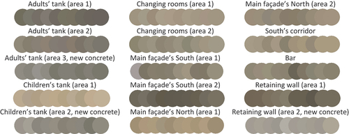
The colour tests were carried out with a spectrophotometer at eight locations of the building, including original concrete and new concrete applied in the intervention. Moreover, ten test repetitions were considered in each location. The results were represented using the Adobe RGB 1998 (). As expected, the results present a high dispersion, with the colour ranging from beige to dark grey. The lighter colours were detected in the children’s tank and the main façade South’s. The new concrete presents also different colour with respect to the original concrete.
Figure 14. Results of the colour analysis.
4.2.2. Cement paste properties testing
Paste cement samples were collected from locations of the structure and the extracted concrete cores (). The samples were used to perform the following tests and analyses in the laboratory: (1) chloride content tests; (2) thermal gravimetric analysis (TGA); (3) nanoindentation; (4) energy-dispersive X-ray analysis (EDS); (5) X-ray diffraction (DRX); (6) scanning electron microscopy (SEM); (7) mercury intrusion porosimetry tests.
Since the building is located very close to the sea (sea water, salt fog, winds and high relative humidity), samples of the cement paste were collected and the chloride content was estimated based on chemical tests performed at the laboratory. The samples were collected at the adults’ tank, the children’s tank and the North’s storage room. The cement paste samples were collected using a drilling machine at different depths (from 10 cm to 30 cm, from the external surface), without contamination of the samples. In general, three samples of each zone were collected, with exception of the children’s tank where four samples were extracted (two at the external mortar layer and two at the original concrete). presents the results of the chemical tests with the estimation of chloride content in the cement paste. In general, the results present a significant chloride content (higher than 1% — upper limit defined by the EN 206–1 (CEN Citation2000)), which decreases in depth. In contrast, the samples of the adults’ tank present an increase of the chloride content in depth. It is noted that it corresponds to a cyclopean concrete with large stones aggregates and, consequently, the samples can also include stone, influencing the percentage of chlorides in the sample. It is also noted that the concrete of the North’s storage room (interior wall) presents a significant reduction of the chloride content in the cement paste at the 30 cm depth (0.18%).
Table 2. Results of the chemical tests to estimate the chloride content in the cement paste.
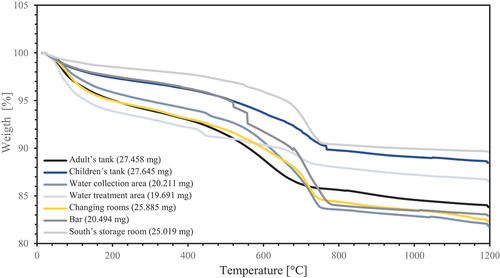
The thermal gravimetric analysis (TGA) was performed in an SDT Q600 thermal analyser of the TA Instruments for a temperature range between 0°C and 1200°C. Seven cement paste samples were analysed. The initial mass of the samples ranges from 19.70 mg and 27.65 mg. The TGA thermal curves () show water release from 0°C to 200°C. Between 400°C and 450°C, the samples of the water treatment area and water collection area present calcium hydroxide (portlandite). There is a significant mass drop around 700°C for all almost samples, which is associated with the presence of calcium carbonate. The TGA results show that these paste cement samples are carbonated, mainly the samples of the exterior wall of the bar, the exterior wall of the changing rooms, the interior wall of the water collection area and South’s storage room (slab with corroded rebars) samples. It is noted the sample of the water treatment area (interior surface of a closed area) presents low carbonation.
Figure 15. TGA thermal curves and initial mass of the samples.
The nanoindentation tests were performed with a nanoindenter tester, provided with a vibrating isolating system and constant temperature and humidity. For each sample, 10 tests were carried, using a 2 × 5 grid (spacing of the horizontal and vertical alignments equal to 75 µm and 250 µm, respectively). All the tests were performed using the same protocol: loading with a constant rate 5 mN/min up to a maximum force, dwell time td = 5 [s] at maximum load and unloading with a constant rate 5 mN/min.
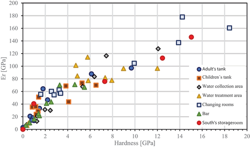
The results of the nanoindentation tests are presented in , namely the hardness and the reduced (effective) elastic modulus obtained from the unloading stiffness (Er). The sample of the Adult’s tank (phase 1) presents a high dispersion in the results, with elastic modulus ranging from 2.98 to 97.16 GPa. Although this is a cement paste sample, the concrete core of the adult’s tank presents a mean Young´s modulus equal to 39.36 GPa (). The samples of the phase 2.1 of the children´s tank and the water collection area present a similar mean elastic modulus, with exception of the sample of the water treatment area (interior surface of a closed area), which presents a higher value (74.56 GPa). The sample of the changing rooms (phase 2.4) presents a mean elastic modulus of 92.75 GPa and the highest value of all tests (177.87 GPa), which can be associated with the many aggregates presented in this sample. The sample of the bar and South’s storage room (phase 3) present very similar mean elastic modulus, namely 37.14 GPa and 37.53 GPa, respectively.
Figure 16. Results of the nanoindentation.
The results of energy-dispersive X-ray analysis (EDS) were combined with the results obtained from X-ray diffraction (DRX), for the final chemical characterization and phases identification, and the analysis based on scanning electron microscopy (magnification of 1000x, 5000x, 10000x and 25000x). As main conclusions, the results of these tests allowed to verify that the samples of the adult’s tank, the children’s tank, the water collection area and the South’s storage room present vaterite, which is a polymorph of calcium carbonate (CaCO3). Moreover, the samples of the children´s tank and the bar present chloride (Cl and Na). The samples present several impurities in the aggregates, which can be an indicator of lack of quality control in the aggregates (e.g. absence or deficient washing and/or uncontrolled origin of the aggregates). Finally, the results of this analysis do not allow to conclude on the presence of pozzolans in the composition of the concretes, which has been a common practice for many years to improve the durability of the concrete.
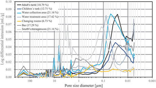
The mercury intrusion porosimetry (MIP) tests were performed to evaluate the pore size distribution of the cement paste samples. The critical pore diameter (dc) is one of the most relevant parameters obtained from the MIP tests, which corresponds to the steepest slope of the cumulative porosity curve and can be determined from the highest point of the logarithmic differential intrusion curve. The logarithmic differential intrusion curves () show that the lowest dc is equal to 0.026 µm and is associated with the sample of the adult’s tank (phase 1). The dc of the samples of phase 2.2 ranges from 0.032 µm (children’s tank) to 0.077 µm (water treatment area). It is noted that the sample of the water collection area (phase 2.1) presents also three relevant peaks for the 10.5114 µm, 6.5834 µm and 5.714 µm pore size diameter. The sample of the changing rooms (phase 2.4) presents a dc of 0.2840 µm associated with the lowest porosity (6.73%), which agrees with the results of the water penetration tests (Section 3.2.1). The sample of the bar (phase 3) presents two relevant ranges of pore size diameter, namely 0.0263–0.0055 µm and 1.3312–0.4341 µm. Finally, the sample of the South’s storage room (phase 3) presents the highest dc, namely 3.8968 µm (sample collected from a slab with carbonated concrete and corroded rebars).
Figure 17. MIP results: logarithmic differential intrusion vs. pore size diameter and porosity.
4.2.3. Steel properties testing
The material and geometric properties of the steel rebars were estimated through laboratory tests and the scanning of the elements with Ground Penetrating Radar (GPR), respectively.
In the laboratory, one steel specimen of the rebar of the retaining wall, three steel specimens of the rebars of the adults’ tank and two steel specimens of the slab of the South’s storage room were prepared and tested, aiming at determining the tensile strength of the steel. The tensile tests were carried out based on the EN 10002–1:2001 (CEN Citation2001). The specimen of the retaining wall presents corrosion (minimum diameter equal to 5.72 mm) and a tensile strength significantly lower (ultimate strength equal to 253 MPa) than the other specimens (). The steel specimens of the adults’ tank have a mean diameter equal to 6.30 mm (smooth rebars without significant corrosion) and ultimate strength equal to 397 MPa. The mean yield strength (fy,0.6fu) of these steel specimens is equal to 238 MPa (), which allows to conclude that this steel corresponds to the class A235 (Portuguese steel class for smooth rebars of normal ductility and yield strength equal or higher than 200 MPa). Finally, two rebars of the slab of the South’s storage room present corrosion and have a mean diameter of 9.44 mm. The mean yield strength (fy,0.6fu) of these two steel specimens is equal to 294 MPa.
Table 3. Summary of the properties of the steel rebar specimens.
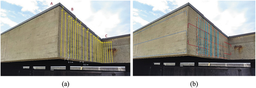
GPR tests were carried out in several locations of the building. The main objective of the GPR tests was to determine the type of connection existing between the beam (B) supported by the two cantilever beams (A and C) located over the changing rooms, for which no design drawings could be found (). Assuming the likely presence of dowels connecting the beams, vertical GPR profiles were carried out each 10 cm (close to the connection) and each 20 cm (around the centre of beam B). The test aimed to determine two specific construction details: (1) the number of dowels connecting the beams; (2) the length of the dowels. The hypothesis for the connections, shown in , indicates the probable presence of two dowels connecting the perpendicular beams in each face (in dark red), making it four it total. It also shows an approximate distribution of the stirrups (in light blue) and the longitudinal reinforcement bars (in orange) of beam B, again in each face. The probable location of the three longitudinal reinforcement bars in beams A and C (in dark blue), and in each face, is also shown. The arrangement is assumed to be symmetric from the vertical axis of the beams. Finally, GPR tests were also carried out at other reinforced concrete walls, aiming to verify the spacing of the vertical and horizontal reinforcement. In the walls of the changing room, the spacing between vertical rebars ranges from 20 to 30 cm, and the rebars are located at a depth of approximately 4 cm. In the exterior wall of the South’s corridor, a spacing of 30 cm and 10 cm between vertical and horizontal rebars were estimated respectively. The horizontal bars are placed at a depth of approximately 2–3 cm. The vertical reinforcement bars seem to be more deeply located, approximately 4 cm within the concrete.
Figure 18. GPR tests on the beam over the changing rooms: (a) location of the GPR profiles; (b) likely reinforcement details of the connection between the beam supported by the two cantilever beams.
4.2.4. Timber properties testing
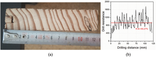
A timber specimen (2 × 12 × 3cm3) was collected from the structure in order to be inspected and tested in laboratory conditions. From an initial visual inspection (), the plank did not present any superficial defects, for example, knots or splits and cracks. There was no slope of grain and the growth rings are regular. The density of the specimen, species is Riga (pinus sylvestris), was obtained according to standard ISO 13061–2 (Citation2014), in which 10 specimens were cut with dimensions of 20x20x25 mm3. The specimens were measured and weighed, and wood density of 635.41 kg/m3 was obtained. Finally, Resistograph tests were performed on the timber specimen to determine the quality of the timber, the presence of possible cavities or decayed parts in the timber specimen not detected by a simple visual inspection. A resistographic measurement of 93.27% was obtained. From the graph (), it is clear that throughout the section, the timber has a good quality, maintaining a uniform resistance.
Figure 19. Survey and testing of the timber specimen: (a) cross-section; (b) resistograph result.
4.2.5. Conclusions
The inspection and diagnosis allowed to conclude that the building presents moderate damage, namely several discrete cracks at the concrete walls, distributed cracking in some walls and corrosion of the steel rebars with detachment of the concrete. The most severe steel corrosion was located at the bottom surface of the slab of the South´s storage room. The concrete walls present differences in terms of deterioration of the surfaces, colour and permeability. The external surface of the tested wall of the changing rooms presented the lower water absorption, the highest compressive strength (estimated by the Schmidt hammer) and velocity of the P waves (obtained from direct sonic tests). The highest water absorption coefficient (1.0 kg/m2.min0.5) occurs at the wall of the water treatment area. A significant chloride content was detected in the concrete of the tanks and the walls of the water collection area and bar, including higher than the upper limit defined by the EN 206–1 (1%).
The test for determining the tensile strength of the steel allowed to conclude that the mean yield strength (fy,0.6fu) of steel specimens of the adults’ tank is equal to 238 MPa (mild steel). The two tested rebars of the slab of the South’s storage room present corrosion and mean yield strength (fy,0.6fu) of 294 MPa. The timber in the building presents high quality, resistance and density, and low moisture content.
The results obtained from the laboratory tests on cement paste samples allowed to obtain detailed data on the cement pastes, such as their chemical characterization, phases and pore size. The highest critical pore, estimated from the mercury intrusion porosimetry tests, was obtained in the sample collected at the slab (bottom surface) of the South’s storage room, which presents steel corrosion. These tests allowed to conclude, as opposed to the results obtained from the concrete carbonation tests with phenolphthalein on-site, that the concrete of all samples is carbonated. The sample collected from a surface previously covered with a switchboard of the water treatment area (closed area) presents low carbonation. These tests also confirmed that there is a high chloride content in the cement paste of the children’s tank and bar, which is also expected for all external surfaces of walls. It is also concluded that the physical, chemical and mechanical properties of the concrete of the building present high dispersion, which is expected since these are concrete mixes made on-site in different phases, with different exposures (tanks, walls without cover, closed areas) and different damage severity.
The low percentage of steel rebars used in the building justifies the low damage associated with corrosion (carbonated concrete and presence of chlorides). Finally, the presence of dilation joints at the connection between walls and slabs prevented the occurrence of damage, at these connections, associated with deformations caused by thermal actions.
5. Pilot demonstration
The cross-analysis of both documentary and physical evidence, latter supported by a series of in situ and laboratory tests, has provided deep knowledge on material characterization and the mechanism of degradation, namely of the concrete. This information was crucial to understand where the concrete repair was feasible using methods of chromatic and texture integration (supported on knowledge from the inspection and diagnosis), avoiding the presence of concrete repair patches in contrast with the existing surface, which was discarded by the architect Álvaro Siza.
In this context, Siza selected two spots for pilot demonstration of concrete repair in the main façade (west) that presented fragmentation and material discontinuity. The first pilot demonstration is a concrete detachment of about 0.5 m2 in the joint (90° angle) between a higher and a lower wall (R1), caused either by the lack of movement joints or by foundation movement (). The second pilot demonstration is located in the same façade at the lower corner of the wall over the concrete bench, where the material discontinuity led to the separation of a wall fragment, possibly due to the dilatation of a corroded vertical rebar () (see pilot demonstrations location on ).
Figure 20. Pilot demonstration of concrete repair: a) Aggregates and pigments for repair mortar; b) Samples for concrete repair (4 of 10); c) R1 before and d) after concrete repair; e) R2 before and f) after concrete repair.
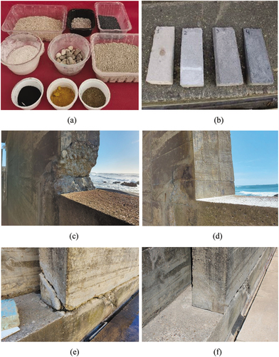
The repair interventions were conducted by the specialized conservator-restorer Pedro Antunes (Cinábrio Restauro) in 2021 and began with the elaboration of restoration mortar samples with different combinations of washed concrete sand, 2/4 mm pebbles, 0/1.2 mm yellow stone dust and 0/0,7 mm black ground limestone (). A quick setting binder was used to allow the application of olive’s shadow and black iron oxide pigments to fine tune the coloration. Ten samples of the repair morter were produced for appreciation and selection by Alvaro Siza, with the objective of an optimised blending and integration of the new mortar with the pre-existing concrete in terms of colour and texture (). The interventions were minimal, employing a restricted number of products, materials and techniques, selected according to their stability, reversibility and temporal inalterability, as well as their compatibility with the original materials.
The repair of the first crack (R1) required the reconstruction of the detachment’s gap volume. With this purpose, 316 stainless steel threaded rods were inserted in the preexisting concrete and coated with epoxy resin before the application of the restoration mortar. A siliconized sheet was then applied on top of it with the objective of keeping the joint open and allowing structural movements. Wooden planks were used as formwork to achieve the intended texture similar to the original. The repair mortar was gently introduced inside the formwork and after 10 to 15 min of curing, a water-soaked sponge was used to mimic the wear in the existing surfaces, followed by a supplementary localized chromatic reintegration to mimic the existing concrete wall’s pigmentation (final result in ).
The repair process of the second area (R2) started with the detachment of the loose fragments and their numbering for later repositioning. The 2 cm corroded vertical rebar was subjected to mechanical and chemical cleaning, followed by the application of a rust converter and an epoxy resin coating to prevent future corrosion. The fragments’ inner surfaces were punctured to allow their realignment with the wall and then glued with an epoxy resin. Lastly, the remaining gap created by the fragmentation was filled with the same mortar and methodology used in the aforementioned intervention. The final result is presented in ).
The pilot demonstration provides an interesting approach to exposed concrete repair, combining scientific information from the testing with the empirical knowledge of the restorer, going beyond the more common approach of patch repair while allowing for more satisfactory results of aesthetic and material integration.
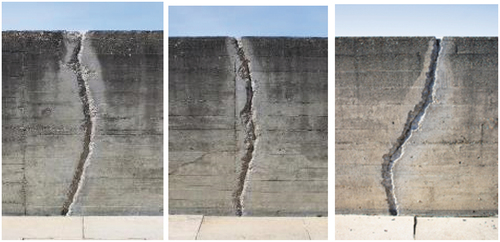
Differently, the other damages present in the building, namely the several vertical cracks on the walls related to the absence of expansion joints in the original design (and are not related to rebar’s steel corrosion), were very difficult to repair with the same approach, because of its bigger dimensions and very irregular geometry. Hence, acknowledging the difficulty of repairing all the anomalies on exposed concrete and assuming the impossibility of disguising ‘patches’ in the concrete — as many of the localized repairs (preferable to a full replacement in his opinion) would necessarily be visible — Siza chose to preserve several cracks open in the exposed concrete as ‘scars of time’ that testify to the material history of the building, see . This is also, in his words, the “most brutalist” attitude and therefore coherent with the option of truth advocated by the use of raw materials in the original project (Ferreira Citation2022, 25).
Figure 21. Vertical cracks due to the absence of movement joints after recent conservation by Alvaro Siza (2021).
With this attitude, Siza provides a pedagogic case study on concrete repair by respecting the building values and namely the cultural significance of concrete (Harboe et al. Citation2021) through minimal intervention (avoiding massive replacement) and case-by-case approach, as preconized in international documents (ICOMOS, Citation2017; Macdonald and Gonçalves Citation2020).
6. Conclusions
The cross-analysis of the ‘documental evidence’ and the ‘physical evidence’ was crucial for the integrated methodology proposed in this paper and is embedded in the following final considerations. The previous knowledge of construction phases and of its building technologies, allowed to better plan the inspection and diagnosis campaigned as to provide complete building assessment and to support conservation planning. Moreover, the data collected on the inspection and diagnosis was an important support for concrete repair in recent conservation by Álvaro Siza, concluded in 2021.
The low percentage of steel rebars used in the building justifies the low damage associated with corrosion (carbonated concrete and presence of chlorides). Also, the presence of dilation joints at the connection between walls and slabs prevented the occurrence of damage, at these connections, associated with deformations caused by the self-weight of the structure and thermal actions.
Pilot demonstrations of concrete repair have profited from the knowledge gathered through the inspection and diagnosis, which the authors believe to be a good example of the benefits of the integrated methodology. The repairs followed the criteria of minimum intervention and compatibility and reversibility as preconized in international recommendations for built heritage conservation (ISCARSAH Citation2003; ICOMOS Citation2017 among others). Thus, this pilot example demonstrates the advantages of using similar principles and methods of the conservation of traditional constructions in modern buildings in concrete, bridging scientific and empirical knowledge, with positive results in terms of technical and aesthetical compatibility.
As regards to this research significance in the field of concrete conservation, it constitutes a valuable contribution to the current state of the art. While there are important studies on the material characterization and mechanisms of deterioration (Di Biase Citation2009; Macdonald and Ostergren Citation2011, among others) and some general guidelines and recommendations (Harboe et al. Citation2021; Macdonald and Gonçalves Citation2020), there are still very few real case studies with the illustration of good practices (Croft and Macdonald Citation2019; ICOMOS France Citation2018). In this way, this paper contributes by providing a pilot demonstration going beyond the more common visible patch repairs which results have been considered unsatisfactory in terms of aesthetic and material compatibility, in the short and medium term (Croft and Macdonald Citation2019, 15) .
The main challenges of this research were the cross-analysis of different sources, methods and techniques, in order to achieve a more complete and holistic approach. Also, the lack of reference case studies on concrete conservation has requested the creation of a specific methodology, deriving from the careful analysis and inspection of the pre-existent fabric. This approach follows the principles of traditional conservation of pre-industrial buildings and applies it to a modern building in exposed concrete.
From this research some recommendations may be outlined: i) the need of interdisciplinary teams for integrated building assessment, since the first stages of the conservation planning; ii) the advantages of the cross-cutting analysis, interpretation and integration of different sources, methods and techniques of building assessment in a common framework (Conservation Management Plan, BIM software, other); iii) methods and principles used in traditional or pre-industrial buildings can be used for exposed concrete conservation.
This paper provides a demonstration on how integrated and interdisciplinary methodologies for building assessment — combining the works of historians, architects, engineers and conservators — are thus of major importance when developing conservation plans, allowing for more rigorous and complete information for the building’s preservation.
Drafting a Conservation Management Plan for the Ocean Swimming Pool benefits from the unique opportunity of engaging the original author in pilot demonstration and in the definition of the guiding principles. Also, the cross-analysis of the documentary and physical evidence, has allowed for the definition of a set of conservation and management policies — i) overarching policies, ii) planning and landscape, iii) risk assessment and climate change adaptation, iv) interpretation and communication, v) conservation, maintenance and use (including user’s manuals and maintenance plan in BIM, currently under implementation).
The building assessment presented in this paper was particularly important for the risk mitigation and climate change adaptation, and conservation, maintenance and use policies, which can prevent or minimize the future damages in the Ocean Swimming Pool. However, hazards such as the sea-level rise, the increase of atmospheric carbon dioxide, the chloride action and storm surges make of this a very vulnerable site. The durability of concrete is determined largely by its deterioration over time which is affected by the environment. The increase in CO2 levels associated with global warming is expected to increase the likelihood of carbonation-induced rebar corrosion. Furthermore, storm surges expose the concrete surfaces to direct contact with seawater, increasing chloride deposition that will accelerate rebar corrosion, resulting in cracking and delamination of the concrete cover and a subsequent reduction of the reinforcement cross section.
In this scenario, a set of monitoring and prevention actions are previewed for the Ocean Swimming Pool i) annual check-ups of concrete structures to assess new damages; ii) every five years with a biocide to remove any biological colonization or other deposits without damaging the surface’s patina; iii) every ten years a structural integrity check-up performed by a specialized team. Hence, respecting Alvaro Siza’s design principles, no deep or intrusive intervention are allowed, so to keep with the original texture and preserving some signs of time that are part of the material history of the building and express its identity.
Finally, the Conservation Management Plan proposes to define an adequate management of change of this landmark architecture still in full use by local communities, mitigating threats and vulnerabilities, while preserving its cultural significance and design principles within the guiding inspiration of Álvaro Siza.
Acknowledgments
The authors acknowledge Hugo Mendonça, Frederico Barbosa, Juan Pedriahita and Hugo Pires for the collaboration in the graphic materials presented in this paper.
Disclosure statement
No potential conflict of interest was reported by the author(s).
Additional information
Funding
References
- ASTM. 2002. Standard test method for pulse velocity through concrete1. C597-02, American Society for Testing and Materials
- Brencich, A., R. Bovolenta, V. Ghiggi, D. Pera, and P. Redaelli. 2020. Rebound hammer test: An investigation into its reliability in applications on concrete structures. Advances in Materials Science and Engineering 2020:1–11. doi:10.1155/2020/6450183.
- Breysse, D. 2012. Nondestructive evaluation of concrete strength: An historical review and a new perspective by combining NDT methods. Construction and Building Materials 33:139–63. doi:10.1016/j.conbuildmat.2011.12.103.
- CEN. 2000. Concrete - Part 1: Specification, performance, production and conformity. EN 206-1:2000, European Committee for Standardization
- CEN. 2001. Metallic materials - Tensile testing - Part 1: Method of test at ambient temperature. EN 10002-1:2001, European Committee for Standardization.
- CEN. 2012. Testing hardened concrete - Part 1: Shape, dimensions and other requirements for specimens and moulds. EN 12390-1:2012, European Committee for Standardization.
- CEN. 2013. Testing concrete in structures - Part 2: Non-destructive testing - Determination of rebound number. EN 12504-2:2013, European Committee for Standardization.
- CEN. 2019. Testing hardened concrete - Part 3: Compressive strength of test specimens. EN 12390-3:2019, European Committee for Standardization
- CEN. 2020. Testing hardened concrete - Part 12: Determination of the carbonation resistance of concrete - Accelerated carbonation method. EN 12390-12:2020, European Committee for Standardization
- Couvidat, J., C. Diliberto, E. Meux, S. Cotelle, C. Bojic, L. Izoret, and A. Lecomte. 2021. Greening effect of slag cement-based concrete: Environmental and ecotoxicological impact. Environmental Technology & Innovation 22. doi:10.1016/j.eti.2021.101467.
- Croft, C., and S. Macdonald, eds. 2019. Concrete: Case Studies in Conservation Practice. Los Angeles: Getty Publications.
- Di Biase, C., ed. 2009. Il degrado del calcestruzzo nell’architettura del Novecento. Santarcangelo di Romagna: Maggioli.
- Ferrão, B. 1945. Perfis-Tipo e dimensionamento de suportes e revestimentos de alvenaria. Porto: Lopes da Silva.
- Ferreira, T. C. 2018. Bridging planned conservation and community empowerment. In Preventive and planned conservation approaches applied to built heritage. Journal of Cultural Heritage Management and Sustainable Development, ed. K. Van Balen, S. Della Torre, F. Cardoso, and A. Vandersand, Vol. 8. 179–93. No. 2. Abingdon: Taylor and Francis. doi:10.1108/JCHMSD-05-2017-0029.
- Ferreira, T. C. 2022. Siza Preserves Siza: Concrete conservation on the Ocean Swimming Pool (2018-2021). In Conserving Concrete/ Restaurer les Betons. Book of Extended abstracts, ed. T. C. Ferreira, and B. Gandini. Porto/ Paris: FAUP/ICOMOS France.
- Ferreira, T. C., and E. Fernandes. 2021. Alvaro Siza’s Tectonic Shift in Leça da Palmeira: From Design to Conservation. In 16th International Docomomo Conference Tokyo Japan 2020+1. Inheritable Resilience: Sharing Values of Global Modernities. Tokyo: Docomomo.
- Ferreira, T. C., E. Fernandes, and F. Barbosa. 2021. Construction culture between tradition and modernity: Three works by Álvaro Siza. In History of Construction Cultures, ed. J. Mscarenhas-Mateus, and A. P. Pires, 570–77. London, United Kingdom: CRC Press - Taylor & Francis Group.
- Ferreira, T. C., and L. Urbano. 2022. No place is deserted. Álvaro Siza: Ocean Swimming Pool (1960-2021). Porto: FAUP/ Afrontamento.
- Ganshirt, C. 2004. Piscina na praia de Leça da Palmeira. Lisbon: Blau.
- Harboe, G., F. Espinosa de Los Monteros, S. Landi, and K. Normandin. 2021. The Cádiz Document InnovaConcrete Guidelines for the Conservation of Concrete Heritage. Cadiz: ICOMOS International.
- ICOMOS Australia. 2013. The Burra Charter: The Australia. ICOMOS Charter for Places of Cultural Significance, ICOMOS.
- ICOMOS France. 2018. Béton(s): Architectures en béton dans les Alpes: Restaurer les bétons, la masse et l’épiderme: Séminaire et colloque internationaux 23 & 24 nov. 2017, Grenoble. Paris: ICOMOS France.
- ICOMOS ISC20C. 2017. Approaches to the conservation of Twentieth-Century Cultural Heritage Madrid – New Delhi document. ICOMOS ISC20C.
- ISCARSAH. 2003. ICOMOS Charter – Principles for the analysis, Conservation and structural restoration of Architectural Heritage. Paris: ICOMOS.
- ISO 13061-2. 2014. Physical and mechanical properties of wood - Test methods for small clear wood specimens - Part 2: Determination of density for physical and mechanical tests.
- Kerr, J. S. 2013. Conservation plan. 7th ed. Sydney: ICOMOS Australia.
- LNEC. 1993. Determination of the Young’s modulus in compression. Lisbon: Nacional Laboratory of Civil Engineering. (Portuguese specification E397)
- Macdonald. 2022. Conservation (management) plans for modern heritage: Relevance, uses and challenges. In Recognising and Managing 20th Century Heritage: Current Issues and Experiences, ed. T. C. Ferreira, and S. Macdonald. Porto/ Paris: FAUP/ISC20C.
- Macdonald, S., and A. P. Gonçalves. 2020. Conservation principles for concrete of cultural significance. Los Angeles: Getty Conservation Institute.
- Macdonald, S., and G. Ostergren. 2011. Conserving Twentieth-Century built heritage: A bibliography. Los Angeles: Getty Conservation Institute.
- Mota, R. 1972. Relatório de Estágio realizado sob a direção de A. Siza Vieira. Porto: ESBAP.
- Ramos, L., M. Morais, M. Azenha, G. Masciotta, E. Pereira, T. C. Ferreira, and P. B. Lourenço. 2018. HeritageCARE: The new project for the preventive conservation of built cultural heritage in the South-West Europe. In Innovative built heritage models. Reflections on cultural heritage theories and practices, ed. K. Van Balen, and A. Vandersande, 135–45. London: CRC Press. doi:10.1201/9781351014793-16.
- Silveira, D., A. Gonçalves, I. Flores-Colen, M. Veiga, I. Torres, and R. Rafael Travincas. 2021. Evaluation of in-service performance factors of renders based on in-situ testing techniques. Journal of Building Engineering 34:101806. doi:10.1016/j.jobe.2020.101806.
- Siza, A., and B. Ferrão. 1967. Memória Descritiva. Processo completo do projecto, incluindo fases construídas e a construir.
- Tosti, F., and C. Ferrante. 2020. Using ground penetrating radar methods to investigate reinforced concrete structures. surveys in Geophysics 41 (3):485–530. doi:10.1007/s10712-019-09565-5.
- Vandesande, A., E. Verstrynge, and K. Van Balen, (Eds.). 2020. Preventive conservation - From climate and damage monitoring to a systemic and integrated approach, 1st ed. London: CRC Press. doi:10.1201/9781003004042
- Vogler, N., P. Drabetzki, M. Lindemann, and H. Kühne. 2022. Description of the concrete carbonation process with adjusted depth-resolved thermogravimetric analysis. Journal of Thermal Analysis and Calorimetry 147 (11):6167–80. doi:10.1007/s10973-021-10966-1.