Abstract
We developed an on-demand multiple-spot holographic optical tweezers (HOT) system based on quasi-simultaneous generation of two intensity-spot patterns by alternately sending the two corresponding hologram patterns to a spatial light modulator. This switching operation reduces the spatial stability of a Brownian particle trapped inside the generated intensity spot. In this study, numerical analysis of the conditions for stable particle trapping in the time-division HOT is conducted using the Smoluchowski equation under the Rayleigh scattering approximation. The relationship between the particle size, the switching rate, and the focused laser beam power is obtained. Experiments confirm the validity of the numerical analysis.
NOMENCLATURE
| a | = |
particle radius |
| c | = |
velocity of light, 3.00 × 10⁸ m/s in vacuum |
| D | = |
diffusion coefficient of the particle suspended in the |
| = |
surrounding medium (water) | |
| F | = |
gradient force exerted on the particle by the incident focused laser beam |
| I | = |
intensity of the incident focused laser beam |
| k | = |
wave number of the incident focused laser beam in the |
| = |
surrounding medium (water) | |
| k B | = |
Boltzmann constant, 1.38 × 10⁻²³ J/K |
| m | = |
relative refractive index of the polystyrene particle against the |
| = |
surrounding medium, m = 1.59/1.33 = 1.20 | |
| N | = |
spatial distribution of the particle position |
| n 2 | = |
refractive index of the surrounding medium, 1.33 for water |
| P | = |
incident laser power |
| r | = |
distance between the focal point of the incident laser and the |
| = |
center of the particle | |
| s | = |
s parameter as functions of the wave number and the beam waist |
| t | = |
time |
| T | = |
absolute temperature of the medium surrounding the particle, 300 K |
| U | = |
optical potential generated by the gradient force F |
| w 0 | = |
beam waist radius of the incident focused laser |
| λ0 | = |
wavelength of the incident light in vacuum, 532 nm |
| η | = |
viscosity coefficient of the surrounding medium, 8.90 × 10⁻⁴ Pa·s |
| = |
for water |
1. INTRODUCTION
A dielectric microparticle can be trapped within a focused beam by the electrical gradient force. This phenomenon has been exploited to optically manipulate microparticles in optical tweezers (Ashkin et al. Citation1986; Ashkin and Dziedzic, Citation1989). Two-dimensional manipulation of particles has been performed in real time by using a galvano-mirror system to deflect a focused laser beam (Sasaki et al. Citation1991). Multiple-spot manipulation has been performed by high-speed scanning with an acousto-optic modulator (Visscher et al. Citation1993). Recent developments in liquid crystal display technology have resulted in the development of a new optical tweezers system that employs a computer-addressed spatial light modulator (SLM); such systems are known as holographic optical tweezers (HOT) (Reicherter et al. Citation1999; Liesener et al. Citation2000). Continuous beam-spot patterns are generated in a HOT system by sending phase-hologram patterns to a SLM, which functions as a phase-hologram generator. HOT systems have greater flexibility for generating the desired intensity pattern than other optical tweezers systems, although SLMs have lower frame rates than galvano-mirror systems and acousto-optic modulators.
In recent years, optical tweezers have been a valuable tool in biological experiments because they are non-destructive and non-invasive. There have been two significant applications of optical tweezers systems to cell biology: single-cell nanosurgery (Jeffries et al. Citation2007) and delivery of DNA into a cell (Kubo et al. Citation2003). We have developed an on-demand time-division HOT system combined with linear phase shifting of Fourier phase holograms that enable nanomaterials to be optically transported into a living cell by the user dragging a mouse cursor on a computer monitor (Yamamoto and Iwai, Citation2008). In this system, two intensity patterns of the beam-spot array are quasi-simultaneously generated by alternately sending two phase-hologram patterns to the SLM.
However, this switching of the beam spot-array patterns greatly reduces the spatial stability of the trapped particle because Brownian motion of nanosized particles is extremely rapid. In this article, we investigate the dependence of the spatial stability of optical trapping on the particle size, laser beam power, and switching rate of the phase holograms. A numerical analysis is performed using the Smoluchowski equation (Schwabl, Citation2002) under the Rayleigh scattering approximation. The optical conditions for stable optical trapping of a particle are obtained numerically and the validity of the numerical analysis in this study is confirmed by experiments.
2. NUMERICAL ANALYSIS OF THE SPATIAL STABILITY OF A~TRAPPED PARTICLE
2.1. Mathematical Formulation of Time-Division Optical Trapping
When a dielectric particle is irradiated by a focused laser beam, two forces act on it: a scattering force and a gradient force. The former is caused a change in the incident light momentum due to light scattering. In this analysis, the total scattering force acting on the particle can be ignored because it acts only parallel to the optical axis. The latter force is induced by the Lorentz force generated by the effect of the electromagnetic field within the beam on dipoles in the particle. When a focused Gaussian laser beam is incident on a particle located at a distance r from the focal point, the transverse trapping force F(r) is proportional to the gradient of the incident intensity I(r) and is given by Smith et al. (Citation1981)
In Eqs. (Equation1) and (Equation2), c is the velocity of light, a is the radius of the particle, n 2 is the refractive index of the surrounding medium, m is the refractive index of the particle relative to n 2, P is the incident laser power, and w 0 is the radius of the beam waist. Equation (Equation1) together with Eq. (Equation2) holds under the Rayleigh scattering approximation of a < λ/20, but even when that criterion is exceeded, the trapping force given by Eq. (Equation1) still agrees well with the force given by the generalized Lorenz–Mie theory (Ren, Gréhan, and Gouesbet, Citation1994; Harada and Asakura, Citation1996).
The description of the electromagnetic field of a highly focused laser beam is considerably more complicated than Eq. (Equation2). For simplicity, the paraxial Gaussian beam described by Eq. (Equation2) under the zeroth-order approximation is employed in this analysis. The measure of the approximation is defined by (Barton and Alexander, Citation1989)
A Brownian particle will be trapped inside the optical potential generated by the gradient force of Eq. (Equation1) together with Eq. (Equation2) but it will still perform Brownian motion within the beam area. The spatial distribution N(r, t) of the position of such a constrained Brownian particle is governed by the Smoluchowski equation (Schwabl, Citation2002):
When the time-varying optical potential for the time-division multiplexing is defined as
2.2. Numerical Simulations
The spatial distribution of the position of the Brownian particle constrained by the optical potential was numerically simulated for a polystyrene particle trapped by a focused laser beam in water. In this case, the parameters are λ0 = 532 nm, T = 300 K, η = 0.000890 Pa·s, n 2 = 1.33, and m = (1.59/1.33) = 1.20. Figure (a) shows the spatial distribution of the position of the Brownian particle constrained by the optical potential defined by Eq. (Equation7) as a function of time and displacement from the focal point and Figure (b) shows its cross section at the focal point. The spatial distribution of the particle is normalized by its integrated value. The Smoluchowski equation was solved for a particle radius of 0.3 µm, a laser power of 1200 µW, a beam waist radius of 0.71 µm, and a switching rate of 5 Hz. The rectangular wave represented by the broken line in Figure (b) shows the time-varying state of the optical potential. The potential is off in the periods when the rectangular wave is zero and the potential is on otherwise. As Figures 1(a) and (b) show, the free diffusion of the particle broadens the distribution when the potential is turned off, whereas the particle is attracted toward the center of the potential when the potential is turned on. Consequently, the particle remains inside the potential and alternates between free diffusion when the potential is off and being attracted to the center when the potential is on.
Figure 1 (a) Spatial distribution of the position of a Brownian particle constrained by the optical potential as a function of time and displacement from the focal point for a = 0.30 µm, w 0 = 0.71 µm, P = 1200 µW, and a switching rate of 5 Hz and (b) Cross section at the focal point of the distribution shown in (a).
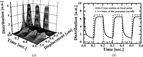
Figure shows the spatial distribution of the position of a constrained Brownian particle as a function of the displacement from the focal point for radii of 0.20, 0.24, and 0.30 µm. In this case the calculation was conducted for a beam waist of 0.71 µm, an incident power of 1200 µW, and a switching rate of 10 Hz. Figure shows that the spatial distribution is broadened and the spatial stability of optical trapping is reduced for smaller particles. This is because the Brownian motion becomes more rapid for smaller particles and the trapping force is proportional to the cube of the particle radius.
Figure 2 Spatial distribution of the position of a Brownian particle with a radius of 0.20, 0.24, and 0.30 µm constrained by the optical potential for w 0 = 0.71 µm, P = 1200 µW, and a switching rate of 10 Hz.
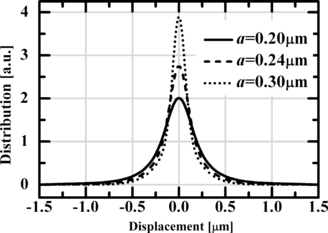
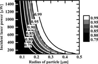
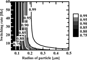
Figure shows a quantitative estimation of the probability that the particle is stably trapped inside the beam waist as a function of the particle radius and the switching rate for an incident power of 1200 µW and a beam waist of 0.71 µm. Due to the limitation of the Rayleigh scattering approximation, the particle radius is restricted to the range 0.05 µm to 0.5 µm. Figure shows that the particle can be trapped more stably within the beam waist with increasing switching rate and particle radius because the particle is illuminated with subsequent laser beam before the particle diffuses freely and the Brownian motion becomes slower, respectively. A particle with a radius larger than 0.35 µm can be securely trapped at a slow switching rate. The probability for stable trapping decreases consistently with particle radius and switching rate. If stable particle trapping is assumed to occur when this probability exceeds 95%, a switching rate of over 10 Hz is required for a particle with a radius larger than 0.2 µm. On the other hand, it is difficult to stably trap particles with radii smaller than 0.2 µm because the probability is lower than 0.95 at any switching rate. The gradient force thus needs to be increased by increasing the incident laser power to stably trap particles with radii smaller than 0.2 µm.
Figure 3 Probability that the particle is stably trapped inside the beam waist as a function of particle radius for w 0 = 0.71 µm and P = 1200 µW.
Figures 4(a) and (b) show the spatial distribution of the position of a constrained Brownian particle as a function of the displacement from the focal point for switching rates of 3, 5, 15, and 60 Hz and at incident powers of 1000, 1200, and 1400 µW, respectively. Figure (a) shows that the base of the spatial distribution broadens with a reduction in the switching rate and thus particle trapping becomes more unstable. On the other hand, Figure (b) shows that the central peak of the distribution increases consistently with increasing incident laser beam power indicating that the particle is trapped more stably at higher laser powers. As shown in Figures 4(a) and (b), the broadening of the base at the lower switching rate means that the particle diffuses freely from the area of the beam spot when the illumination is off and the increase in the central peak at higher incident laser powers means that the particle is fixed at the center of the optical potential.
Figure 4 Spatial distribution of the position of a constrained Brownian particle as a function of displacement from the center: (a) Switching-rate dependency of the distribution profile for a = 0.30 µm, w 0 = 0.71 µm, and P = 1200 µW and (b) Incident-power dependency of the distribution profile for a = 0.30 µm, w 0 = 0.71 µm, and a switching rate of 15 Hz.
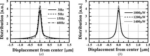
Figure shows the probability that the particle is stably trapped inside a beam waist of 0.71 µm as a function of the particle radius and the incident laser power for a switching rate of 37.5 Hz, which corresponds to the maximum frame rate of the SLM (LC-R 2500 SLM, Holoeye) used in previous experiments. Due to the limitation of the Rayleigh scattering approximation, the particle radius is restricted to the range 0.05 µm to 0.5 µm. As seen from the figure, the particle is trapped more stably inside the beam waist with increasing incident laser power and the particle radius due to increase in the gradient force and the Brownian motion becoming slower, respectively. A particle with a radius larger than 0.4 µm can be securely trapped at incident laser powers lower than 200 µW. The probability of stable trapping decreases consistently with decreasing particle radius and it never exceeds 90% for particles smaller than 0.3 µm; the numerical analysis for this result is experimentally confirmed in the following section. This section has demonstrated that numerical analysis can be used to find suitable optical conditions for stable optical trapping of a particle by the time-division multiplexing method under the limitation of the Rayleigh scattering approximation.
3. EXPERIMENT
3.1. Experimental Setup
The numerical simulation results were confirmed by experiments. Figure shows the experimental setup. The laser beam, which has a wavelength of 532 nm, was chopped by a beam chopper at a frequency in the range 5 to 60 Hz and a duty cycle of 0.5, instead of using a time-division hologram. The laser beam was expanded by a beam expander, was guided to a beam splitter, and then passed through an aperture, a polarizer, and a λ/4 plate. The laser beam reflected by the beam splitter was focused in the sample by an objective lens LO with a numerical aperture of 0.9. The beam waist in the focal plane of the objective lens was set to 0.71 µm by adjusting the diameter of the pupil aperture. In this case, the measure of the zeroth-order approximation given by Eq. (Equation3) is estimated to be approximately s = 0.09 and thus the experimental results contain errors of a few percent. The dynamic behavior of the trapped particle was recorded by a CCD camera at a frame rate of 30 Hz. In the experiments, the sample was a water suspension of polystyrene particles, whose parameters were T = 300 K, η = 0.000890 Pa·s, n 2 = 1.33, and m = 1.59/1.33 = 1.20.
Figure 6 Experimental setup. The laser beam wavelength was λ = 532 nm. The numerical aperture of the objective lens LO was 0.75 or 0.90. A suspension of polystyrene particles was set in the focal plane of the objective lens.
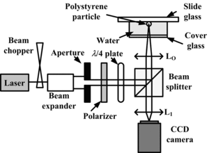
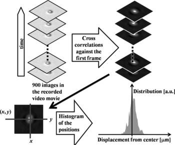
Figure schematically shows the procedure for measuring and calculating the spatial distribution of the trapped particle position. The Brownian motion of a particle trapped inside the beam waist region was recorded by the CCD camera. The particle positions were determined by calculating the spatial cross-correlations between the first frame and all the other 900 frames in the 30s movie. Notice that the particle position can be determined exactly by measuring the spatial cross-correlation function, although the recorded images are blurred due to the diffraction limit of the objective lens. Finally, the spatial distribution of the position for the constrained Brownian particle can be experimentally obtained from the histogram of the coordinates of the cross-correlation peaks.
3.2. Experimental Results
Figure shows a comparison between the spatial distribution of the particle position obtained by the experiments and the numerical calculations for a 0.30 µm-radius particle at switching rates of 5, 15, and 60 Hz shown in Table . All distributions were normalized by their areas. By varying the switching rate, the experiments confirm the theoretical prediction regarding the influence of free diffusion of the particle when the laser beam illumination is off to the probability distribution of the particle position. The agreement between the experimental and numerical results shown in the figure confirms the validity of the theoretical analysis based on the Smoluchowski equation defined by Eq. (Equation4).
Figure 8 Comparison between the spatial distributions of the particle position obtained by experiments and numerical calculations for the conditions shown in Table 1. The notation “sim” and “exp” indicate the simulation and experimental results, respectively.
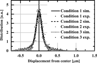
Table 1. Conditions of the experiments
4. CONCLUSIONS
In this article, we investigated the spatial stability of a trapped particle in a HOT system based on time-division multiplexing. In this investigation, the potential obtained under the Rayleigh scattering approximation was applied to the Smoluchowski equation. The dynamic properties of the particle trapped by a switching beam spot were successfully estimated and suitable conditions for stable particle trapping were found by numerical analysis. Finally, experiments confirmed the accuracy of the numerical analysis conducted in this study.
REFERENCES
- Ashkin , A. , J. M. Dziedzic , J. E. Bjorkholm , and S. Chu . 1986 . Observation of a single-beam gradient force optical trap for dielectric particles . Opt. Lett. 11 ( 5 ): 288 – 290 .
- Ashkin , A. and J. M. Dziedzic . 1989 . Internal cell manipulation using infrared laser traps . Proc. Natl. Acad. Sci. USA 86 ( 20 ): 7914 – 7918 .
- Barton , J. P. and D. R. Alexander . 1989 . Fifth-order corrected electromagnetic field components for a fundamental Gaussian beam . J. Appl. Phys. 66 ( 7 ): 2800 – 2802 .
- Harada , Y. and T. Asakura . 1996 . Radiation forces on a dielectric sphere in the Rayleigh scattering regime . Opt. Commun. 124 ( 5 ): 529 – 541 .
- Jeffries , G. D. M. , J. S. Edgar , Y. Zhao , J. P. Shelby , C. Frog , and D. T. Chiu . 2007 . Using polarization shaped optical vortex traps for single-cell nanosurgery . Nano. Lett. 7 ( 2 ): 415 – 420 .
- Kubo , K. , M. Ichikawa , K. Yoshikawa , Y. Koyama , T. Niidome , T. Yamaoka , and S.-I. M. Nomura . 2003 . Optically driven transport into a living cell . Appl. Phys. Lett. 83 ( 12 ): 2468 – 2470 .
- Liesener , J. , M. Reicherter , T. Haist , and H. J. Tiziani . 2000 . Multi-functional optical tweezers using computer-generated holograms . Op. Commun. 185 ( 1 ): 77 – 82 .
- Reicherter , M. , T. Haist , E. U. Wagemann , and H. J. Tiziani . 1999 . Optical particle trapping with computer-generated holograms written on a liquid-crystal display . Opt. Lett. 24 ( 9 ): 608 – 610 .
- Ren , K. F. , G. Gréhan , and G. Gouesbet . 1994 . Radiation pressure forces exerted on a particle arbitrarily located in Gaussian beam by using the generalized Lorenz-Mie theory, and associated resonance effects . Opt. Commun. 108 ( 6 ): 343 – 354 .
- Sasaki , K. , M. Koshioka , H. Misawa , N. Kitamura , and H. Masuhara . 1991 . Optical trapping of a metal particle and a water droplet by a scanning laser beam . Appl. Phys. Lett. 60 ( 7 ): 807 – 809 .
- Schwabl , F. 2002. Statistical mechanics . Berlin : Springer.
- Smith , P. W. , A. Ashkin , and W. J. Tomlinson . 1981 . Four-Wave mixing in an artificial Kerr medium . Opt. Lett. 6 ( 6 ): 284 – 286 .
- Visscher , K. , G. J. Brakenhoff , and J. J. Krol . 1993 . Micromanipulation by “multiple” optical traps created by a single fast scanning trap integrated with the bilateral confocal scanning laser microscope . Cytometry Part A 14 ( 2 ): 105 – 114 .
- Yamamoto , J. and T. Iwai . 2008 . On-demand optical tweezers using computer-generated phase holograms . Rev. Laser Eng. 36 : 1331 – 1334 .
