Abstract
Atmospheric turbulence compensation for the next generation of terrestrial telescopes (30–40 m diameter) will require deformable mirrors of increasing size and a number of actuators reaching several thousands. However, the mere extrapolation of existing designs leads to complicated and extremely expensive mirrors. This article discusses an alternative solution based on the use of segmented identical hexagonal bimorph mirrors. This allows to indefinitely increase the degree of correction while maintaining the first mechanical resonance at the level of a single segment, and shows an increase in price only proportional to the number of segments. Extensive simulations using random turbulent screens show that the segmentation produces only moderate reductions of the Strehl number, compared to a monolithic bimorph mirror with the same number of actuators (S = 0.86 instead of S = 0.89 in this study).
NOMENCLATURE
| A | = |
surface area of the active aperture of the deformable mirror |
| D | = |
interaction matrix between applied voltages and displacements induced |
| d 31 | = |
in-plane piezoelectric coefficient |
| DM | = |
deformable mirror |
| D M1 | = |
diameter of primary mirror |
| E | = |
electrical field |
| ELT | = |
Extremely Large Telescope |
| E–ELT | = |
European Extremely Large Telescope |
| f 1 | = |
first resonance frequency |
| f G | = |
adaptive optics bandwidth |
| FoV | = |
field-of-view |
| IF | = |
influence function |
| LS | = |
least squares |
| MEMS | = |
micro electro-mechanical system |
| N | = |
number of actuators |
| NIR | = |
near infrared |
| PZT | = |
piezoelectric |
| R | = |
radius of curvature |
| RMS | = |
root mean square |
| r o | = |
fried length |
| SVD | = |
singular value decomposition |
| t | = |
thickness of substrate or piezoelectric active layer |
| TMT | = |
Thirty Meter Telescope |
| U | = |
displacement mode-shapes of singular modes |
| V | = |
voltage shapes of singular modes |
| v | = |
voltage |
| vel | = |
velocity |
| VLT | = |
Very Large Telescope |
| W max | = |
stroke of bimorph mirror |
| w | = |
displacements effectively induced |
| w T | = |
target displacements |
| Y | = |
Young modulus |
| λ | = |
wavelength |
| Σ | = |
gains of singular modes |
| σ | = |
root-mean-square of Zernike mode |
| θ | = |
light deviation angle |
1. INTRODUCTION
Deformable mirrors (DM) are the most mature means of wavefront correction in adaptive optics. DM can range from micro-electromechanic devices (MEMS) with only a few mm of diameter to large active secondary mirrors of telescopes larger than 1 m, depending on their position in the optical train and on the specific application envisaged; their actuators can be piezoelectric, magnetic, or electrostatic.
DM must adjust their shape in real-time to the random changes introduced by atmospheric turbulence to the optical path of light emitted by far away astronomical objects. By employing up to 1,000 actuators, they have been capable of canceling atmospheric blur and allowed the current generation of terrestrial telescopes, which have primary mirrors in the order of 8–10 m of diameter, to outperform existing space telescopes. The next generation of terrestrial telescopes is represented by the American Thirty Meter Telescopes (TMT) and the European Extremely Large Telescope (E-ELT), which will have 42 m of diameter. Such larger apertures will collect much more complex aberrations introduced by atmospheric turbulence, and the number of actuators of deformable mirrors required to correct them will grow accordingly. In order to meet the requirements of future ELTs, the simple up-scaling of current designs may be extremely costly for some technologies, or not possible.
The very high number of actuators required by high order adaptive optics can be achieved through the assembly of hexagonal bimorph mirrors as a honeycomb, which constitutes a rupture in the design paradigm of DM. This approach preserves the required temporal bandwidth of correction, by maintaining the resonance frequency of the entire system at the lower limit of a single segment, and also shows the low-cost, light-weight, and robustness inherent to the simplicity of the bimorph configuration. Moreover, the segments being all identical can be mass-produced, which brings enormous advantages in terms of cost. One challenge posed by this approach is the loss of control authority at the edges of the bimorph segments.
This article demonstrates analytically that it is impossible to scale-up a monolithic bimorph mirror and preserve its first resonance frequency and thus its control bandwidth, and shows through extensive simulations that the edge effects resulting from its segmentation do not significantly hamper its morphing capability. This remains almost as good as that of a monolithic bimorph mirror with the same number of actuators, provided that the electrode layout, which is used to apply complex voltage patterns to the piezoelectric (PZT) active layer, be refined in the vicinity of the edges of the segments.
The main parameters of a DM are the number of actuators, the stroke, the size, and the temporal bandwidth. The linearity and hysteresis have only a second order impact on performance, or might only be relevant in specific applications.
Number of Actuators. In a terrestrial telescope, the number N of actuators required in a deformable mirror for correcting atmospheric turbulence can be estimated by splitting the diameter D M1 of the primary mirror in terms of sub-apertures having a diameter equal to the atmospheric turbulence coherence length, r o (Fried, Citation1965). The total number of actuators needed will be equal to the number of such sub-apertures, since it is assumed that within each of them the effects of atmospheric turbulence are negligible. The coherence length r o is an inverse measure of the intensity of turbulence in a given astronomical observation. It depends on the observation site, the time of day, and the angle of observation. It increases with the wavelength of observation λ according to Hardy (Citation1998): Current corrections in the NIR at the very large telescope (VLT) of 8 m of diameter are done with about 60 actuators (Donaldson et al., Citation2000), and with more than 1,000 in the visible (Arsenault et al., Citation2006). Extrapolation with Eq. (Equation2) shows needs in the order of the 10000s in the future ELTs. | |||||
Stroke. The maximum deformation of a DM defines its stroke. The required stroke is independent of the wavelength of observation and increases with the size of the primary mirror of the telescope. The stroke root-mean-square (RMS) in the VLT is of the order of 1 µm and in the ELTs will be above 5 µm. The stroke of a DM shows a strong dependence on the actuation principle and its boundary conditions. The maximum relative displacement that can be imposed between two actuators is called the inter-actuator stroke, and determines the maximum amplitude of correction to the optical mode with the highest spatial order. | |||||
Size. The optical train of a telescope transforms a collimated beam of light with the diameter of a primary mirror D M1 on a collimated beam of light with the diameter of a DM, D DM. The angles of deviation of light with relation to the optical axis at different points of the optical system are related by the Lagrange Invariant. When applied to a telescope, it states that the product of the deviation angle θ, and the diameter of the collimated beam remains constant, therefore, The maximum deviation θ accepted by the telescope defines its field-of-view (FoV). Therefore, the light from an object deviated of the FoV will impinge on the deformable mirror with a deviation angle magnified by the ratio of diameters between the primary mirror and the DM. In practice, the design of the optical train and the packaging of all the optical components (wavefront sensors, scientific instruments, and multiple DMs) becomes very complicated for high deviation angles θ′ thereby imposing a lower limit to the diameter of DM, D DM. Moreover, increasing the size of M 1 proportionally increases the minimum acceptable diameter of the DM. A preliminary optical design for the TMT (Bauman, Citation2003) identified that its FoV of 1′ would result in deviation angles of θ′ = 17°at the adaptive optics correction if MEMS deformable mirrors with D ap = 30 mm diameter were used. This deviation angle was considered too high for a feasible optical design and a lower limit of D ap = 300 mm was proposed. | |||||
Temporal bandwidth. The bandwidth of correction required for atmospheric turbulence can be estimated by considering a frozen layer of turbulence blown by the wind with velocity vel over a coherent sub-aperture of diameter r o . It is therefore independent from the diameter of the primary mirror M 1, and for a given turbulence intensity it decreases for longer λ. Typically it is in the order of 100 Hz in the visible and 20 Hz in the NIR. A high bandwidth of the DM can be passively achieved by guaranteeing that mechanical resonances remain high enough and providing enough damping. Alternatively, additional electronic stiffness and damping can be provided by the control system. | |||||
Hysteresis and linearity. The predictability of the response is essential for open-loop and feed-forward operations. The linearity of a DM can always be improved by calibration of a lookup-table. Hysteresis, which is very significant in PZT actuators, is automatically corrected in a closed-loop despite involving some loss of bandwidth. It can also be mitigated by controlling the PZT in charge rather than in voltage. | |||||
2. STATE-OF-THE-ART DEFORMABLE MIRRORS
Adaptive optics in future ELTs will require larger deformable mirrors with a larger stroke and a much larger number of actuators. This scale-up of the DM will typically lead to a reduction of their first resonance frequencies, and therefore of control bandwidth, and to an increase in price.
The classical principle of actuating deformable mirrors is to apply out-of-plane forces to a flexible optical plate, and adjust its shape to the changes in the optical path introduced by atmospheric turbulence. In the most mature designs of deformable mirrors, these forces can be generated with piezoelectric actuators formed by stacking multiple individual elements—piezostacked (Loktev and Vdovin, Citation2008; Sinquin, Lurçon, and Guillemard, Citation2008) or by voice coils that push and pull permanent magnets bonded to the optical plate (Arsenault et al., Citation2006; Miller et al., Citation2004; Riccardi et al., Citation2008), as illustrated in Figure .
Figure 1 Physical principles for deforming a mirror with out-of-plane linear actuation. (a) Piezo-stacked actuators, (b) voice-coil magnetic actuators, (c) electrostatically-actuated MEMS mirror, and (d) electrostatically actuated membrane mirror. (Figure is provided in color online.).
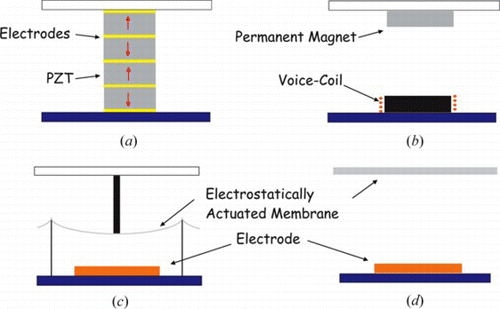
The up-scaling of these designs will not degrade their bandwidth of correction, but will increase their weight and will therefore increase the dynamic coupling to the telescope structure. Moreover, they constitute already very expensive and complex mechanisms and are fabricated by long and cumbersome processes. These drawbacks will become even more critical when scaling up to meet the requirements of the future ELTs.
Silicon micro-system technologies (MEMS) (Norton et al., Citation2009; Perreault et al., Citation2002) allow the production of very small mirrors with a very high number of actuators and at a very low cost. However, these mirrors are very limited in size and are only suited for niche applications with a small field of view, such as extreme adaptive optics and multi object adaptive optics. The actuation principle of MEMS mirrors, depicted in Figure c, consists of electrostatic forces generated between an array of electrodes covering the back-plate and the membranes supporting the small pylons that transmit the forces to the optical plate at discrete points.
Silicon milling techniques also allow the low-cost production of deformable mirrors consisting of electrostatically actuated membranes (Loktev and Vdovin, Citation2008; Zhu et al., Citation1999). In this configuration, the optical membrane is constrained at the edges and deforms under the action of a directly applied electrostatic force (Figure d). The strokes produced are very high, but the inter-actuator coupling is very nonlinear. Also, since the electrostatic forces can only be attractive the reference shape must be concave, which introduces specific constraints to its integration in the optical system. Because the membrane can only be fixed at its edges, these types of mirrors cannot be scaled up without a loss of control bandwidth, but nevertheless they remain very popular in portable applications like in ophthalmology.
2.1. Bimorph Mirrors
In an alternative to out-of-plane forces, the shaping of a deformable mirror can be induced by in-plane piezoelectric layers through the bimorph effect. Bimorph mirrors have a very simple configuration, and so they are lightweight and can be easily produced at a low-cost. However, in bimorph actuation the increase in stroke and the number of independent actuators requires the enlargement of the mirror, which is inherently incompatible with maintaining a high enough bandwidth of correction. Bimorph mirrors are currently commercially available with a few hundred of actuators, and have performed very well for corrections in the NIR (Oya et al., Citation2004, Citation2006; Paufique et al., Citation2004; Sinquin, Lurçon, and Guillemard, Citation2008).
The bimorph principle of actuation is illustrated in Figure a. Two piezoelectric layers, each coated by electrodes on both faces, are bonded together and an electrical field E is applied through them in the direction perpendicular to the plane of the mirror. An adequate choice of the direction of polarization and of the connectivity of the electrodes allows to impose in-plane elongations in opposite directions for the two piezoelectric layers. The compatibility of displacement at the interface will induce the bending of the bimorph mirror. Inverting the sign of application of the electrical field will produce bending in the opposite direction. The shape illustrated in Figure corresponds to the application of a positive voltage to the left addressing electrode and a negative voltage to the right one. The metallic optical coating applied on the top of the mirror also works as a common ground electrode and can be covered by a thin layer of glass to protect it against damage. The utilization of an identical configuration at the bottom of the mirror results in a symmetrical laminate, which is insensitive to temperature changes.
Figure 2 Principle of bimorph actuation. (a) Two active layer bimorph mirror and (b) monomorph mirror. The shape induced results from the application of a positive voltage to the left addressing electrode, and a negative voltage to the right one. (Figure is provided in color online.).
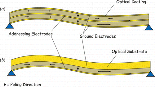
The out-of-plane bending of the mirror originating from in-plane actuation can also be effectively achieved by utilizing one piezoelectric layer adherent to a passive substrate (Figure b). The production of these monomorph mirrors becomes particularly interesting due to its greater simplicity when the piezoelectric layer consists of a thin film deposited on the back of an optical substrate. However, due to their unsymmetrical configuration, preserving its shape in the face of temperature changes is not so straightforward as in the configuration with two piezoelectric layers.
In the bimorph actuation, the action exerted by the piezoelectric layers corresponds to a bending moment distributed along their limits. Considering a kinematic mount to the mirror and a single electrode, a spherical shape is produced. The maximum curvature that can be induced is proportional to the applied voltage v and the piezoelectric material constant d 31, and decreases with the thickness t of the mirror with the corresponding radius of curvature being given by
Since the out-of-plane displacements produced are very small with relation to the size of the mirror, the shape can be accurately approximated by a paraboloid. The stroke of the mirror W max can then be shown to vary quadratically with its diameter D DM.
Since the first resonance frequency of the mirror f 1 varies according to (Blevins, Citation1979)
Applying the analysis above to the action of a single actuator, leads us to the fact that for guaranteeing its minimum amplitude of deformation (e.g., as needed for meeting inter-actuator stroke requirements), there is a minimum area that must be assigned to it and increasing the number of actuators requires enlarging the mirror. In this way, increasing the number of actuators of a bimorph mirror becomes incompatible with preserving the bandwidth of correction by maintaining a sufficiently high first resonance frequency, according to Eq. (Equation8).
For the sake of simplicity the term bimorph is used throughout this article to designate both the bimorph mirrors with two active layers and the special case consisting of monomorph mirrors.
3. SCALABLE BIMORPH MIRRORS
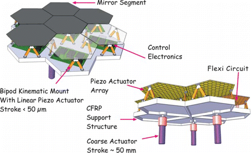
An alternative design is shown in Figure . It preserves the advantages of low cost, low mass, and robustness of the bimorph mirrors, and overcomes the problem of a low resonance mode for a high number of actuators. By applying the segmentation to this mirror, the first resonance frequency will be limited to that of a single segment. Moreover, the segments being identical can be mass-produced at a very low cost and by choosing a hexagonal shape, they can be assembled indefinitely as a honeycomb to reach the required number of actuators. The principle of actuation will combine the bimorph shaping within each segment with their rigid body actuation for guaranteeing continuity of deformation.
Figure 3 Segmented bimorph mirror: CAD view of a group of seven segments on its support structure. (Figure is provided in color online.).
3.1. Simulating the Morphing of an Assembly
This section presents the results of numerical simulations showing the morphing capability of an assembly of bimorph mirrors with the shapes of the polynomials of Zernike in a highly continuous manner. The simulation method has been applied for predicting the deformation of a single segment and the correlation observed with the experimental results was very good (Rodrigues et al., Citation2009).
3.1.1. Description of the method
The numerical procedure for simulating the morphing is schematized in the flowchart of Figure .
Figure 4 Numerical procedure for simulating the morphing of a segmented bimorph mirror.
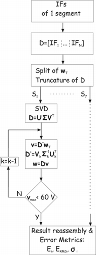
The process starts by computing all the displacement influence functions (IF) of each PZT patch actuator of an hexagonal bimorph mirror. This is done by the finite-element analysis using multilayer thin-shell elements with piezoelectric capabilities (Piefort, Citation2001; Preumont, Citation2006). The mirror is assumed simply supported at three points, and the value used for the PZT coefficient d 31 results from the past test-analysis correlation (Rodrigues et al., Citation2009). Additionally, the rigid body influence functions are computed for each linear actuator respecting the geometric constraints associated to the three simple support points. All the IFs are then stacked into an interaction matrix D that is the same for all the identical hexagonal bimorph segments of the assembly, and in which each column relates the voltages applied to the PZT patches with the respective actuator and the out-of-plane displacement induced on the surface of the segment on a set of control points.
Subsequently, the interaction matrix D is adapted for the position of each segment by, in each case, excluding the lines corresponding to the control points located outside the common active aperture. Similarly, the target displacement w T , which consists of the Zernike polynomials up to radial order 8 to be generated within the active aperture, is split among the seven sub-apertures corresponding to the different segments, and which are illustrated in the assemblies of Figure .
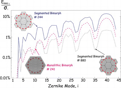
Figure 5 RMS error produced for the generation of Zernike modes up to order 8. Comparison between segmented bimorph mirrors and monolithic bimorph mirror. The values are relative to the RMS value of each mode. (Figure is provided in color online.).
For each segment, the interaction matrix D then undergoes a singular value decomposition (SVD) (Strang, Citation1988).
The SVD decomposes the relation between the applied voltages and the generated shapes into independent orthogonal modes. The matrix U contains the displacements associated to each singular mode and is capable of generating the same displacement space as the entire set of the IFs. The matrix V contains the set of voltages that generate each singular mode. Since both U and V are orthonormalized, the matrix Σ is diagonal and contains the gains of each singular mode between the set of voltages that generates it and the resulting displacement amplitudes.
The SVD allows to iteratively perform the least-squares (LS) fit of the target shapes on the displacement space of the bimorph segments until all the applied voltages, which are the coefficients of the fit, remain below the threshold of the maximum voltage available.Footnote 1 In each iteration, the displacement space generated by U is truncated by removing the most ill-conditioned singular mode. This mode offers the poorest contribution to shape correction and at the highest cost of applied voltages (experimentally, these are also the modes more sensitive to noise). This process is performed in parallel and is fully decoupled between all the segments.
Finally, the results computed independently for each segment are reassembled on the common active aperture of area A and the root-mean-square (RMS) of the error between the target, and the effectively generated shape is computed for all Zernike modes and compared with the RMS of the corresponding shapes.
3.1.2. Morphing the shapes of the Zernike modes
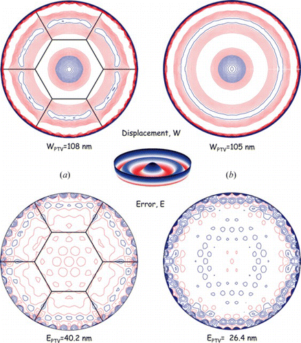
The ratio between the error RMS (E RMS) and the RMS of the target Zernike mode shape (σ) is depicted in Figure . The results refer to two honeycomb assemblies of seven bimorph mirrors and one circular monolithic bimorph mirror analyzed through the same procedure but skipping the split step. One assembly contains hexagonal segments with 43 PZT patches and three linear actuators each, totalizing 244 actuators within the active aperture while the other assembly uses segments with 175 patches, totalizing 880 actuators within the active aperture. The monolithic mirror employs 241 patches within the active aperture. In the three cases, the active optical aperture is identical and has a diameter of 400 mm.
A comparison of the error for the assembly and for the monolithic bimorph mirrors with essentially the same number of actuators in the active aperture show that the discontinuity between the segments in the assembly mostly degrades the morphing with the shapes of the low order Zernike modes. For the high order modes, a convergent tendency is observed between the segmented and the monolithic bimorph mirror. It can also be noted that because of the use of a kinematic mount by the segmented bimorph mirrors, these mirrors are capable of generating the modes of defocus (mode #4) with a lower error than the monolithic mirror and by employing linear actuators, they can exactly generate tilt even with an active aperture that reaches the physical limits of the assembly.
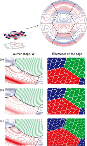
Using the actuator layouts shown in Figure , the contour plots of the shapes generated and the corresponding errors committed are illustrated in Figures for the cases of Defocus, Astigmatism, and purely radial Zernike mode of the eighth order. The lower error for the Defocus mode (Figure ) achieved with the assembly of bimorph segments is now even more evident, with the error introduced by the edges being in the same order as the print-through, resulting from the discontinuity between the PZT patches. In the case of the monolithic bimorph mirror, the error is higher at the boundaries of the active aperture.
Figure 6 Comparison of the actuator layouts of (a) one segmented and (b) one monolithic bimorph mirror. Each segment of the assembly in (a) contains 43 PZT pactches and three linear actuators, totalizing 322 actuators, of which about 244 lie within the active optical aperture. The monolithic layout (b) consists of a honeycomb with 331 actuators, with about 241 inside the active aperture. (Figure is provided in color online.).
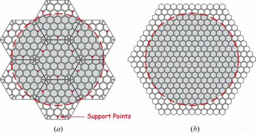
Figure 7 Generation of Defocus. (a) Segmented bimorph and (b) monolithic bimorph. Generated shape (top) and error committed (bottom) when employing a segmented bimorph mirror (left) and a monolithic bimorph mirror (right), with the layouts represented in Figure 6. The steps between contours are different for each plot. (Figure is provided in color online.).
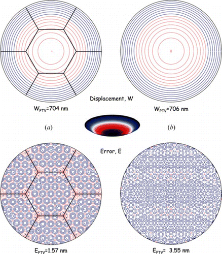
Figure 8 Generation of Astigmatism. (a) Segmented bimorph and (b) monolithic bimorph. Generated shape (top) and error committed (bottom) when employing a segmented bimorph mirror (left) and a monolithic bimorph mirror (right), with the layouts represented in Figure 6. The steps between contours are different for each plot. The inter-segment region within the box is magnified in Figure 9, where the reduction of the error is shown for an increased refinement of the actuator array. (Figure is provided in color online.).
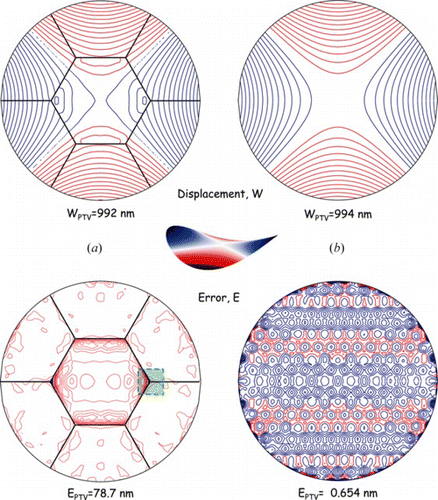
Figure 9 Reduction of the error at the segment edge by consecutive refinement of the actuator array: (a) 244 actuators, (b) 880 actuators, and (c) 1696 actuators. (a) is the same as the layout (a) in Figure 8. The contour step is equal to 2.62 nm in the three cases. (Figure is provided in color online.).
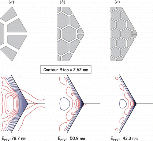
Figure 10 Generation of purely radial Zernike mode of the eighth order. (a) Segmented bimorph and (b) monolithic bimorph. Generated shape (top) and error committed (bottom) when employing a segmented bimorph mirror (left) and a monolithic bimorph mirror (right), with the layouts represented in Figure 6. The steps between contours are different for each plot. (Figure is provided in color online.).
For the generation of the Astigmatism (Figure ), the segmented bimorph mirror shows a lower performance with the error being concentrated at the edges of the central segment. However, this degradation of the morphing caused by, the segmentation can be mitigated by refining the actuator array at the edges of the segment, as illustrated by Figure . This mitigation is characterized by a decrease of the absolute value of the error, shown by a reduction of the number of contour levels, and a concentration at smaller and smaller regions which result in a much smaller error RMS.
Finally, for the generation of a high order Zernike mode such as the purely radial mode of the eighth order (mode #40), the loss of performance caused by the segmentation looses significance with the distribution of the error at the edges of the segments now having the same magnitude as the fitting error at the interior of the segment, caused by insufficient actuator resolution. The loss of authority in shape correction observed at the edges of the segments can be understood in the sense that a point located at the edge of a segment, and especially at a corner, is located further away from the majority of the PZT patches as opposed to a point at the center of the segment, and since the displacement field introduced by the PZT patches decreases with the distance they will have less authority for controlling its out-of-plane displacement. This effect can be mitigated by refining the actuator layout at the edges and even splitting in two corner actuators. The gradual increase in authority observed by a gradual refinement of actuators can be seen in Figure .
Figure 11 Detail of the generation of high order coma (mode #17), showing the smoothing of the shapes between the segments for different layouts of actuators. Figures (a), (b), and (c) correspond to a gradual refinement of the actuators. (Figure is provided in color online.).
3.1.3. Morphing random turbulent screens
The capability of a segmented bimorph mirror to correct atmospheric turbulence was evaluated and compared to that of a monolithic one. The actuator layouts considered are those illustrated in Figure , which have approximately the same total number of actuators within the active aperture. The intensity of turbulence was scaled for the case of observations in the NIR made at the VLT to which corresponds a ratio of the diameter of the primary mirror of the telescope to the atmospheric turbulence coherence length of D/r 0 (2.2 µm) = 8.1/0.731 = 11.31.
The simulation of the turbulence compensation is detailed by Rodrigues (Citation2010), and consists of the following steps.
-
Generation of an ensemble of 100 turbulent phase screens ϕ i by superposing the first 495 Zernike modes (radial order 30th) with randomly generated coefficients with statistics following the Kolmogorov model of atmospheric turbulence (Roddier, Citation1999; Roggeman and Welsh, Citation1996).
-
Conversion of the turbulent phase screens to mirror target deformations.
-
Fitting of the target deformations on the singular modes of the deformable mirror by LS, saturating the applied voltages within ±60 V.
-
Determination of the average total phase variance by converting the E RMS of the fitting of the mirror shape back to phase, adding 0.078 rad2 which represents the nonsimulated phase variance (Zernikes above 495), and averaging in the ensemble,
-
Computing the Strehl of the corrected image by,
-
Iterate steps 3–5 while adjusting the number of retained singular modes for optimizing S.
The Strehl number characterizes the blurring of an image caused by aberrations intrinsic to the optical system or introduced by the environment. It quantifies the ratio of the peak of energy in the image of a point source with relation to the ideal case of a diffracted limited system, i.e., with the resolution limited only by the size of its aperture. In these simulations, it was observed that the residual turbulence remaining after the adaptive optics correction resulted on images with a Strehl number of 0.86 for the case of the segmented bimorph mirror (with the layout of Figure a) and of 0.89 for the monolithic bimorph mirror (with the layout of Figure b).
Figure refers to the correction of the first turbulent screen and shows the ideal shape required for the mirror, the shape effectively generated, and the difference between them achieved by segmented and by monolithic bimorph mirrors.
Figure 12 Correction of the first turbulent screen of the ensemble, for observations at λ = 2.2 µm in the VLT. Target shape, which corresponds to half of the aberrated wavefront, shapes effectively imposed to the segmented bimorph (left) and monolithic bimorph (right), and respective uncorrected residuals. The segmented bimorph shows a higher residual at the edges of the segment, but due to its concentrated character its impact in the error RMS is smoothed. (Figure is provided in color online.).
4. CONCLUSION
This article has examined the possibility of using an array of segmented bimorph mirrors for adaptive optics of future extremely large telescopes. This configuration allows to achieve several thousands of degrees of freedom with appropriate stroke at a moderate cost (only proportional to the number of segments), while keeping the first natural frequency independent of the size of the array (equal to that of one segment). Extensive numerical simulations suggest that the morphing capability of this system is appropriate for the application, and that the segmentation produces only a moderate reduction of the optical quality of the AO mirror. For the example treated here, the Strehl number was 0.86 to be compared with 0.89 for a monolithic mirror with a similar number of actuators in the active aperture.
ACKNOWLEDGMENTS
Gonçalo Rodrigues acknowledges Fundaço para a Ci
ncia e a Tecnologia, (FCT), Portugal for his Ph.d. grant SFRH/BD/21732/2005, and Renaud Bastaits acknowledges Fonds National de la Recherche Scientifique (FNRS), Belgium for his FRIA Ph.d. grant FC76554.
Notes
In this case, the threshold of 60 V was imposed for consistency with the experiment reported in Rodrigues et al. (Citation2009), and which resulted in an acceptable hysteresis for PZT patches with the same thickness as herein.
REFERENCES
- Arsenault , R. , R. Biasi , D. Gallieni , A. Riccardi , P. Lazzarini , N. Hubin , et al. . 2006 . A deformable secondary mirror for the VLT. In Advances in Adaptive Optics II, eds. D. Bonaccini Calia and Ellerbroek. Proc. SPIE 6272.
- Bauman , B. 2003. Optical design for extremely large telescope adaptive optics systems. Ph.d. thesis, University of Arizona.
- Blevins , R. D. 1979 . Formulas for natural frequencies and mode shapes . New York : Van Nostrand Reinhold Company .
- Donaldson , R. , D. Bonaccini , J. Brynnel , B. Buzzoni , L. M. Close , B. Delabre , et al. 2000 . MACAO and its application for the VLT interferometer . In adaptive optical systems technology , ed. P. L. Wizinowich , pp. 82 – 93 . Proc. SPIE 4007 .
- Fried , D. L. 1965 . Statistics of a geometric representation of wavefront distortion . J. Optical Society of America 55 ( 11 ): 1427 – 1435 .
- Hardy , J. W. 1998 . Adaptive optics for astronomical telescopes . New York : Oxford University Press, Inc .
- Loktev , S. O. , G. Vdovin , eds. 2008 . Adaptive optics technologies . Delft : OKO Technologies .
- Miller , D. L. , G. Brusa , M. A. Kenworthy , P. M. Hinz , and D. L. Fisher 2004 . Status of the NGS adaptive optic system at the MMT telescope . In Advances in adaptive optics , eds. D. Bonaccini Calia , B. L. Ellerbroek and R. Ragazzoni . pp. 207 – 215 . Proc. SPIE 5490 .
- Norton , A. , J. W. Evans , D. Gavel , D. Dillon , D. Palmer , B. Macintosh , K. Morzinski , and S. Cornelissen 2009 . Preliminary characterization of Boston Micromachines' 4096-actuator deformable mirror . In MEMS adaptive optics III , eds. S. Olivier , T. Bifano , and J. Kubby . Proc. SPIE 7209 .
- Oya , S. , A. Bouvier , O. Guyon , M. Watanabe , Y. Hayano , H. Takami , et al. 2006 . Performance of the deformable mirror for Subaru LGSAO . In Advances in adaptive optics II , eds. B. L. Ellerbroek , and D. Bonaccini Calia , p. 62724S. Proc. SPIE 6272 .
- Oya , S. , O. Guyon , M. Watanabe , Y. Hayano , H. Takami , M. Iye , et al. 2004 . Deformable mirror design of Subaru LGSAO system . In Advancements in adaptive optics , eds. D. Bonaccini Calia , B. L. Ellerbroek , and R. Ragazzoni , pp. 1546 – 1555 . Proc. SPIE 5490 .
- Paufique , J. , P. Biereichel , R. Donaldson , B. Delabre , E. Fedrigo , F. Franza , et al. 2004 . MACAO-CRIRES: A step toward high-resolution spectroscopy . In Advancements in adaptive optics , eds. D. Bonaccini Calia , B. L. Ellerbroek , and R. Ragazzoni , pp. 216 – 227 . Proc. SPIE 5490 .
- Perreault , J. A. , T. G. Bifano , B. M. Levine , and M. N. Horenstein , 2002 . Adaptive optic correction using micro-electro-mechanical deformable mirrors . Optical Eng. 41 ( 3 ): 561 – 566 .
- Piefort , V. 2001 . Finite element modelling of piezoelectric active structures. Ph.d. thesis, Université Libre de Bruxelles.
- Preumont , A. 2006 . Mechatronics—dynamics of electromechanical and piezoelectric systems, Solid mechanics and its applications. The Netherlands: Springer, Dordrecht.
- Riccardi , A. , M. Xompero , D. Zanotti , L. Busoni , C. Del Vecchio , P. Salinari , et al. 2008 . The adaptive secondary mirror for the large binocular telescope: Results of acceptance laboratory test . In Adaptive optics systems , eds. C. E. W. Pl. L. Hubin , N. Max Proc. SPIE 7015 .
- Roddier , F. 1999 . Adaptive Optics in Astronomy . Cambridge , UK : Cambridge University Press .
- Rodrigues , G. M. C. 2010 . Adaptive optics with segmented deformable bimorph mirrors. Ph.d thesis, Université Libre de Bruxelles.
- Rodrigues , G. , R. Bastaits , S. Roose , Y. Stockman , S. Gebhardt , A. Schoenecker , P. Villon , and A. Preumont . 2009 . Modular bimorph mirrors for adaptive optics. Optical Eng. 48(3):034001–034001-7.
- Roggeman , N. and B. Welsh . 1996 . Imaging through turbulence . The CRC Press Laser and Optical Science and Technology Series. Boca Raton , FL : CRC Press .
- Sinquin , J.-C. , J.-M. Lurçcon and C. Guillemard . 2008. Deformable mirror technologies for astronomy at CILAS. In Adaptive optics systems , eds. C. E. W. P. L. Hubin and N. Max . Proc. SPIE 7015.
- Strang , G. 1988 . Linear algebra and its applications. , 3rd ed . San Diego : Harcourt Brace Jovanovich, Publishers .
- Zhu , L. , P. Sun , D. Bartsch , W. Freeman , and Y. Fainman . 1999 . Adaptive control of a micromachined continuous-membrane deformable mirror for aberration compensation . Appl. Optics 38 ( 1 ): 168 – 176 .