Abstract
This article describes the design, implementation and characterization of a novel optical tweezer system. The system utilizes a deformable mirror, wavefront sensor and controller to manipulate an optically trapped micro-particle within a small chamber. This method for optical trapping employs technology adopted from astronomical instrumentation; in particular, adaptive optics. A deformable mirror is employed to control the wavefront phase of a laser beam before it is imaged into a chamber by a high numerical aperture microscope objective lens. The wavefront phase is measured by a Shack–Hartman wavefront sensor and the particle's position monitored by a video camera. The goals of the work presented here are to trap particles ranging in size from 1 μm to 10 μm; create a suitable controller for moving trapped particles in three dimensions; image the trapped particle; determine the prototype system's performance specifications; and determine the trap stiffness.
NOMENCLATURE
| a | = |
bead location on the imaging camera in pixels |
| AO | = |
adaptive optics |
| CCD | = |
charge coupled device |
| d c | = |
controller output vector of DM control voltages |
| DM | = |
deformable mirror |
| f C | = |
corner frequency, Hz |
| k trap | = |
trap stiffness, N/m |
| LA | = |
lenslet array |
| NA | = |
numerical aperture |
| OT | = |
optical tweezer |
| r | = |
particle radius |
| S D | = |
vector of WFS offset pixel locations |
| S E | = |
error signal |
| SHWFS | = |
Shack–Hartman wavefront sensor |
| S M | = |
vector containing the lenslet focus positions |
| S N | = |
vector of the desired spot locations on SHWFS |
| S R | = |
reference SHWFS vector |
| S xx | = |
power spectral densityin Nm2/Hz |
| T+ | = |
matrix that relates SHWFS measurements to trap position |
| T S | = |
chamber temperature, °K |
| W+ | = |
interaction matrix |
| WFS | = |
wavefront sensor |
| β | = |
Stokes drag on a sphere, Nms |
| η | = |
dynamic viscosity, Ns/m2 |
1. INTRODUCTION
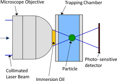
In the early 1970s, Ashkin (Citation1970) discovered that a transparent microsphere, suspended in an aqueous solution, was stably held in three dimensions at a laser's focus. Commonly referred to as an optical tweezer (OT), these devices utilize a collimated laser beam directed into the trapping zone by a high-numerical aperture (NA > 0.9) microscope objective, see Figure . As the microspheres are on the same length scale as biological specimens, such as cells (Ashkin and Dziedzic, Citation1987), this technique has become an invaluable tool in the field of microbiology. Subsequently, non-contact processes have been developed for measuring the small forces restraining the trapped cell within the beam's focus, and also for manipulating its location (Block, Citation1990). Single beam optical trapping is possible based on the balance between two types of optically induced forces; scattering forces, which push the trapped particle along the beams axis and gradient forces that pull the particle along the spatial gradient of light intensity. When the gradient forces and scattering forces balance, the object becomes fixed in space. The underlying physics behind optical trapping has been extensively covered elsewhere (Block, Citation1990; Moffitt et al., Citation2008; Dholakia and Reece, Citation2006; Molloy and Padgett, Citation2002; Harada and Toshimitsu, Citation1996) and will not be repeated.
Figure 1 A simple geometry for a single beam optical trap showing the collimated input laser beam, high NA oil-immersion microscope objective and trapped particle suspended in an aqueous solution. (Figure is provided in color online.).
Microscope objectives, a major part of any optical tweezer system, are designed for imaging, and are well defined by their resolution and working distance. In optical tweezing applications, the minimum trappable particle size is related to the beam resolution, and the maximum possible trapping depth, is related to the working distance. The location of the trap's position (beam focal point), within a chamber located immediately after the objective, can be modified through control of the input optical beam's phase, before it enters the back aperture of the objective (Molloy and Padgett, Citation2002).
This article describes a novel method for moving the location of the trap through the adoption of techniques from the field of adaptive optics. The prototype system employs a deformable mirror (DM), wave front sensor (WFS), and control system to modify the location of the trapped particle three dimensionally in a closed loop.
In the context of previous research and development on optical tweezer systems, the major categories presented in the literature are the following: (1) beam steering employing acousto-optical deflectors (Glynne-Jones and Boltryk, Citation2009) or galvonometer steering mirrors (Sasaki and Masanori, Citation1991); and (2) beam phase modulation using spatial light modulators (van der Horst and Forde, Citation2008; Liesener and Reicherter, Citation2000). The beam steering methods move the laser focus within the confines of the trapping chamber and can also move multiple traps by time sharing the beam across each target. Spatial light modulators are employed to implement computer generated holograms that create the trap or multiple traps. In this work, a phase adjustment is applied to the laser beam by means of a deformable mirror whose shape control is integrated with a wavefront sensor. Hence, the technique falls into the former classification and is also highly adaptable to being expanded to create multiple traps.
2. BEAM CONTROL EMPLOYING ADAPTIVE OPTICS
2.1. Adaptive Optics Technology
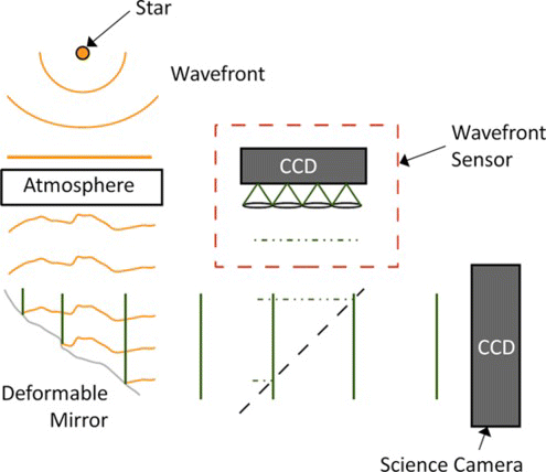
Adaptive optics (AO) technology is employed in astrophysical instrumentation as a means for the real-time removal of optical aberrations, created by the atmosphere (Beckers, Citation1993). A typical AO system, see Figure , employs a deformable mirror to correct the wavefront distortions, as measured by a wavefront sensor. A Shack–Hartman wavefront sensor (SHWFS) employs a lenslet array and a charge coupled device (CCD) to measure the wavefront's slope at discrete locations over the wavefront.
Figure 2 A generic astrophysical AO system utilizing a DM and wavefront sensor. (Figure is provided in color online.).
In this work, the DM employs a grid of 52 micro voice-coil actuators (ALPAO) to control its reflecting surface shape (as illustrated in Figure ). The reflective surface is a flexible membrane fixed to a stationary ring outside the last set of actuators. The characteristics of the DM, presented in Table , are large stroke, zero hysteresis, and very high linearity between applied actuator voltage and stroke. An array of small magnets are attached to the back of the reflecting surface; when current flows through each coil the magnet above is attracted or repelled depending on the direction of current.
Figure 3 An electromagnetic-based deformable mirror where the actuators are formed by small magnets and micro DC voice coils: (a) Current in each coil creates an electromagnetic attraction/repulsion with the corresponding magnet. (b) Several of the total (52) actuators are outside of the pupil to minimize the effect of the restrained edge. (Figure is provided in color online.).
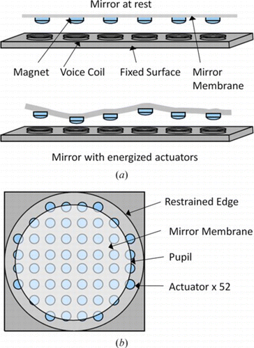
Table 1.
A SHWFS delivers signals (Δx, Δy), proportional to the wavefront's phase, to a controller that derives the DM's drive signals. In astronomical applications, wavefront aberrations are created by fluctuations in the atmosphere's refractive index due to warm and cool air mixing (Roddier, Citation1999). In this work, as explained below, wavefront phase modifications are deliberately applied to a laser beam in order to control the position of a particle contained within a trapping chamber. Wavefront sampling is accomplished using a grid of micro lenses called a lenslet array (LA). As shown in Figure a, each lenslet samples a local region of the wavefront and, therefore, creates a focal spot whose displacement from its null position (as defined by a perfectly flat wavefront) is dependent on the local slope of the wavefront. In the presence of aberrations, each spot is offset from its home position (dotted circle) and the offsets are measured by the CCD.
Figure 4 The Shack–Hartmann wavefront sensor measures phase gradient: (a) In the one dimensional sense, the beam phase is sampled by a grid of micro lenses, called a lenslet array, each focusing onto a region of the CCD called a subaperture. (b) The focal point displacement (Δx, Δy) is related to average phase gradient (slope) within the respective subaperture. (Figure is provided in color online.).
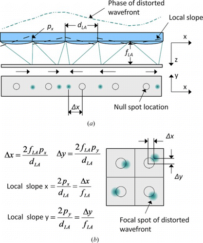
In Figure b each centroid displacement is measured by first thresholding the CCD image intensity values and then applying Eq. (Equation1) to the outputs within each subaperture.
2.2. Optical Aberration Theory
The phase of a wavefront is often described using Zernike polynomials. Zernike modes are a set of polynomials that are orthogonal on a unit disk (which is useful for the circular beam shapes in most optical systems) and, therefore, a wavefront can be modeled as a sum of a series of Zernike polynomials. Zernike polynomials have the further advantage that the lower order modes represent common wavefront errors such as: tip, tilt, defocus, astigmatism, spherical aberration, and coma. The definition of Zernike polynomials (Noll, Citation1976) is given for reference in Eqs. (Equation2) and (Equation3).
For: m ≥ 0, 0 ≤ ρ ≤ 1, 0 ≤ θ ≤ 2π
And
For: m < 0, 0 ≤ ρ ≤ 1, 0 ≤ θ ≤ 2π
where is the normalization factor given below.
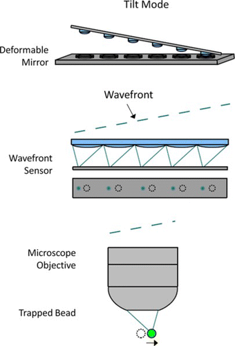
The majority of wavefront errors (aberrations) practically encountered can be described using the first 20 modes. Also, as the polynomial order increases, so does the spatial frequency of wavefront error. The highest order Zernike mode that can be corrected by a DM increases with the number of DM actuators. The mode shapes for the first 5 Zernike modes are shown in Figure . An example of how the DM creates the tip/tilt mode is shown in Figure with the resulting SHWFS spots and the motion of the trapped bead. Combinations of the tip/tilt mode with the focus mode allow fully three dimensional particle motions.
Figure 5 The first five Zernike modes displayed by radial order and physical description (e.g., focus and coma). (Figure is provided in color online.).
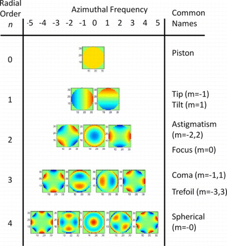
Figure 6 An example of how the tip/tilt mode is created on the DM, and the resulting response from the SHWFS and the trapped bead. The surface of the DM, lenslet array and the back aperture of the microscope objective are all conjugate. (Figure is provided in color online.).
3. EXPERIMENTAL ARRANGEMENT
A schematic diagram of the experimental apparatus is shown in Figure . A fiber laser, with variable output power between 0.5 and 5 W, is used as the beam source. To prevent these relatively high laser powers from damaging potential biological samples, a wavelength of 1060 nm is used. A lens pair (L1, L2) expands the beam, from 2.2 mm to 15 mm diameter, to match the DM pupil. The beam then enters the back aperture of the trapping objective (O1), through lenses L3 and L4, which resize and focus the beam into the trapping chamber. The light exiting the chamber is focused using objective (O2) onto a position sensitive detector (photodiode). As the trapped bead can be effectively thought of as an additional lens in the optical train, any displacement of the bead will shift the laser focus on the detector accordingly.
Figure 7 Schematic diagram of the prototype optical trapping system. The lens pairs (e.g., L1, L2) act to resize the beam diameter to fit the pupil of the DM, SHWFS, imaging camera, and back aperture of the trapping objective O1. (Figure is provided in color online.).
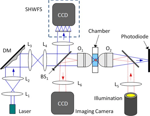
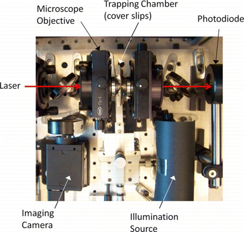
A beam splitter (BS1) reflects 8% of the beam power into a SHWFS through lens L5. The SHWFS lenslet array, having a 0.188 mm pitch and an 8 mm focal length, creates a set of individual beams, in a grid pattern, which form foci on the CCD (Dalsa 128 × 128 pixel). In order to illuminate the trapped particles in the chamber, diffuse white light is focused onto the back aperture of the second objective (O2) illuminating the trapping chamber, see photograph of Figure . The objective O1 images the trapped particles onto the imaging camera (Point Grey Research, Grass Hopper) through lens (L6).
Figure 8 Photograph of the trapping chamber region showing the microscope objectives and cover slips. (Figure is provided in color online.).
The trapping chamber design is rigidly defined by the surrounding optical components. Because the trapped particles are being imaged by two objectives, on both sides of the chamber, the particle (polystyrene bead of diameter 1 to 10 microns) solution is enclosed by two cover slips. The separation between the cover slips is approximately 0.15 mm which ensures that the polystyrene beads can be viewed simultaneously from both sides. These constraints determined the design of a trapping chamber best described by its construction shown in Figure .
Figure 9 (a) Construction of the trapping chamber from two 0.17 mm thick microscope cover slips and a layer of Parafilm. (b) Spatial coordinate system within the trapping chamber. (Figure is provided in color online.).
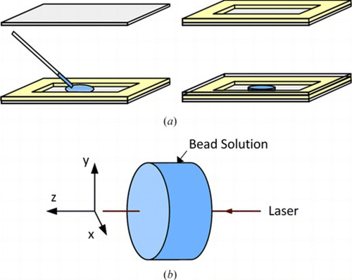
A 0.17 mm cover slip is used as the lower surface and a Parafilm rectangle, roughly the size of the slip with a void cut in its center, is sandwiched between by a top cover slip. As shown in Figure a, a small droplet of the solution, containing the beads, is placed on the lower cover slip and the entire assembly, is heated and compressed, causing the film to bond to the slips. This method is both inexpensive and quick and also allows the operator to rapidly change from one bead size to another. Each chamber has a usable lifetime of about a day, due to either the oil destroying the Parafilm or the water in the chamber evaporating. The diagram of Figure b shows the spatial coordinate system employed within the chamber. The positive Z axis is in the direction of the laser beam through the chamber. The vertical XY plane is orthogonal to the Z axis. Overall, the size of the chamber is 10 mm × 8 mm, with a thickness of 0.15 mm.
4. TRAP CONTROL EMPLOYING AN ADAPTIVE OPTICS APPROACH
The software controller's function is to accept the desired trap position, as defined by the user, as input and create the necessary DM shape commands to correctly manipulate the wavefront and thereby position the trap inside the chamber. The DM input signals, generated by the controller, are derived from the SHWFS measurements. The controller adjusts the DM shape incrementally, based on minimizing the difference between the actual SHWFS measurements and the desired SHWFS positions (as derived from the user input). In order to achieve this goal, two calibration matrices are first created: (1) Matrix W that relates the SHWFS measurements to DM command voltages. (2) Matrix T that relates the trap position to SHWFS measurements.
4.1. Deformable Mirror—SHWFS Control Loop
The controller parameters are defined below, with reference to Figure :
Figure 10 The control system block diagram illustrating how a desired trap location is converted into DM command voltages. The DM and WFS are modeled as single delays Z-1, in control terms. (Figure is provided in color online.).
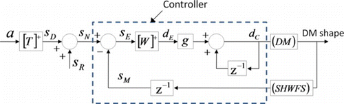
| a | = |
bead location on the imaging camera in pixels. |
| S D | = |
a vector of WFS offset pixel locations derived from the desired trap position input p, through the application of matrix T + (the pseudo-inverse of matrix T). |
| S R | = |
reference SHWFS vector containing the x, y pixel locations for each lenslet focus when the trap is at its rest or null position. |
| S N | = |
a vector of the desired spot locations on the SHWFS. |
| S E | = |
error signal between the current and desired SHWFS spot locations. |
| S M | = |
SHWFS vector containing the lenslet focus positions formed by sampling the beam, after its wavefront is shaped by the DM. |
| d c | = |
controller output vector of DM control voltages for each actuator created by multiplying the error signal S E by the inverse of the interaction matrix W +. It should be noted that matrix W is not strictly invertible and, therefore, the method of singular value decomposition is employed to calculate the pseudo-inverse of W. The calculation of W and W + is only performed once during the setup procedure. |
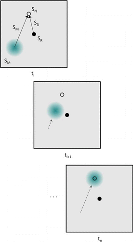
Through a process of calibration, it is known that when the SHWFS measurements (S N ) equals the sum of S D and S R , the trap will be at the desired location.
The error signal is found from
Figure shows the relationship between S R , S N , S E , and S M on one SHWFS focal spot. The error signal S E is transformed into a DM control voltage by application of the matrix W + and a gain factor g.
Figure 11 Schematic of the controller parameters as they relate to the SHWFS spots on the CCD. Each spot is moved, in a series of increments, to a desired position based on the required bead location. (Figure is provided in color online.).
The controller is also able to move the trap in the z direction; however, since there is no “z” position sensor, the z movements are not calibrated in terms of true position in the trapping chamber. Instead, WFS offsets S D are generated using the Zernike focus mode.
4.2. Calibration of the DM Commands to SHWFS Measurements
An interaction matrix, or poke matrix, W, is created by energizing each actuator individually with a voltage h, while all other actuators are set to null. The resulting SHWFS measurements, s i are recorded to form W.
Each column w i of W is measured after applying a voltage h to each actuator and recording the vector of measurements s i (where i denotes the actuator). Therefore, each column w i records the normalized SHWFS response to a given motion of each actuator. Hence, W is an m × n matrix, where m is double the number of lenselets and represents the (x, y) position of each focal point on the CCD array, and n is the number of actuators on the DM. The required calibration is then determined from the pseudo-inverse of W, W +. The calibration matrix then relates a desired set of SHWFS measurements (s) to DM voltages (d) through
4.3. Calibration of the Trap Position to SHWFS Measurements
It is necessary to convert the desired trap location, a, to the SHWFS offsets S D . This relationship was created experimentally by trapping a bead and then adding an offset S D to the reference S R , thereby moving the DM in tip-tilt mode and recording the SHWFS measurement S M . The corresponding bead location, a, for the new trap position, was then recorded. This process was repeated; changing the SHWFS offset SD to move each lenslet in a rectangular grid pattern, corresponding to various amounts of DM tip-tilt. This process fully characterized the relationship between trap location a and SHWFS offsets S D . Overall, an interaction matrix T was formed and each column of T contained the relationship between a specific focal spot's motion on the SHWFS and the degree of DM tip-tilt required to move the spot over the full spatial range of the SHWFS. A linear least-squares fit was performed on the data in each column of T, the slope of the fitted line inverted, and a matrix T + generated that provides the offset values S D from trap position a.
4.4. Removal of System Aberrations
There are aberrations in the system created by small misalignments, lenses, air turbulence, and the interface between the immersion oil required for the microscope objective and the aqueous bead solution. In the case of optical misalignments and lens aberrations, the SHWFS measured these static errors in terms of subaperture centroid displacements. The controller can drive these centroid locations to their respective null locations, which can then be converted into the Zernike modes shown in Figure a. The largest static aberration modes are defocus Z 3, astigmatism Z 7, Z 8 and some coma Z 5. These modes were recorded and then used to remove the static aberrations from the system as shown in Figure b. Early results in the case of removing spherical aberrations caused by the oil-glass-solution interfaces are promising; by correcting this phenomenon the trap stiffness should not sharply degrade with depth. Figure shows how the focal point from a flat beam degrades with increased trapping depth.
Figure 12 (a) Zernike mode representation of the static wavefront error of the optical system. (b) Zernike representation of the wavefront error with the AO controller activated. (Figure is provided in color online.).
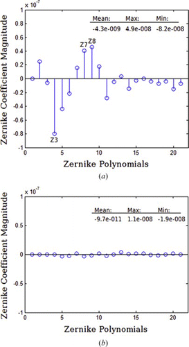
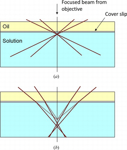
Figure 13 Light focused using an oil-immersion microscope objective is refracted by the oil-solution interface causing spherical aberrations which degrade trap stiffness: (a) shows a tight focus close to the cover slip and (b) shows an extended focus at increased depth, degrading the trap stiffness. (Figure is provided in color online.).
5. OPTICAL TRAPPING SYSTEM CHARACTERIZATION
In this section, the optical trapping system's operating specifications and the method of characterizing the trap's stiffness are presented.
5.1. Trap Operational Parameters
The basic operational performance parameters of the optical trapping system are presented below:
Clock rate: Employing the current PC, the AO controller runs in closed-loop at 20 Hz. Based on manufacturers' specifications, the maximum clock rate for the DM is 750 Hz and 200 Hz for the SHWFS. | |||||
Spatial range (X, Y): The imaging camera's CCD was calibrated and found to have 0.119 microns/pixel. The CCD resolution is 1600 by 1200 pixels in the X and Y axes, respectively. By moving a trapped particle through the entire range of motion, as controlled by the DM, and performing image processing (centroiding) on the image, the range of motion is measured as 28 microns in X and 30 microns in Y. | |||||
Spatial range (Z): This range was measured using the video monitoring camera and observing the particles Z motion through the observable range of focus. The Z spatial range of motion is estimated to be 40 µm. | |||||
Minimum step size: The controllable minimum change in the X and Y location of the trap is 0.067 microns. The trap position measurement is subject to errors created by the random Brownian motion, and also by errors in the image processing methodology. The standard deviation of the trap position measurement was used to determine experimental accuracy. A 10 um particle was trapped using 12 mW of optical power and its rest position was measured for each of 300 hundred frames. The standard deviation of the centroid in x and y was 0.041 um and 0.042 um, respectively. The magnitude of the standard deviation due to thermally induced Brownian motion is influenced by the trap stiffness and decreases with increasing trap stiffness. | |||||
5.2. Trap Stiffness Characterization
In this work, a frequency-domain analysis technique is employed to calibrate trap stiffness. An optically trapped particle is displaced from its rest position if an additional external force is applied (e.g., collision with another particle in the fluid). The optical trap's restoring force is proportional to the bead's displacement (assuming this displacement is small) and the trap stiffness is modeled by a measurable spring constant, k trap. The Fourier transform of the polystyrene bead's position (as measured on the photodetector) yields a Lorentzian-shaped power spectrum. The power spectrum of the trapped particle's position, as it experiences the random vibrational motion caused by molecular collisions, is recorded. At low Reynolds number, the power spectrum of the trapped particle is given by (Svoboda and Block, Citation1994):
Assuming spherical particles in a low Reynolds number solution, sufficiently far away from any walls, β is equal to 6π η r as shown in Svoboda and Block (Citation1994), where η is the dynamic viscosity of the surrounding fluid and r is the trapped particle radius. This method is based entirely on the frequency response of the trapped particle and does not require knowledge of actual particle displacement, which is challenging to accurately determine experimentally.
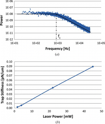
As shown in Figure , the stiffness is experimentally measured on the 2-axis photodiode (DL100-7PCBA3) after the beam exits the trapping chamber. The photodiode's signals are converted into digital form by a data acquisition system (National Instruments USB 6221) and processed on a personal computer using the MATLAB libraries. The results of the trap stiffness characterization are presented in the chart of Figure . Figure a shows an example of the power spectral density measurement taken for a trapped polystyrene bead of diameter 1 µm. In this figure, the roll-off frequency (f 0) is found from the intersection of two best fit lines through the data points. This process was repeated for a number of laser power levels and, as shown in Figure b, the corresponding trap stiffness values were calculated and recorded. The relationship between laser power and trap stiffness was found to be linear, which is typical. Employing the stiffness calibration values, the force applied to a particle can now be measured for the optical trapping system presented.
Figure 14 (a) Power spectral density measurement of a single trapped particle for a laser power of 10 mW measured at the entrance to the microscope objective. (b) Trap stiffness for different laser powers. The average error in the stiffness was estimated to be 10% of the displayed values. (Figure is provided in color online.).
5.3. Discussion of the Performance Parameters and Future Improvements
The spatial range in (x, y) within the trapping chamber is currently limited by the SHWFS. The lenselet focal length is too long and, at the maximum extent of the spatial (x, y) range, the centroids move out of their respective subapertures. This causes the control algorithm to fail. In theory, the spatial range using the same DM and trapping objective could be extended to 60 um in X and Y (greater than 50% further than currently achievable). In the planar motion sense, the trap position is controlled by the DM tip/tilt mode in a linear fashion. A 1 pixel change in SHWFS position is equivalent to a change in trap position of 1.33 um, or 11.17 pixels on the imaging CCD. This specification is comparable to the positional accuracy reported using devices such as spatial light modulators and acousto-optic deflectors.
Future work will focus on upgrading the design to include:
A multi-trap system will be implemented by modifying the optical design and control software. Independent (x, y, z) control of four discrete traps, arranged in a 2 × 2 array, using the essential components of the above AO method can be accomplished. The optics will be modified to include an additional lenslet array in the trapping path, before the microscope objective. This optical element will subdivide the beam into four overlapping beams on entry into the objective. An additional collimating lens will be required between the new lenslet array and objective. | |||||
The control software will be extensively modified to enable independent closed loop motion control of each trap. | |||||
An investigation of the trap stiffness as it relates to the position of the particle in the trapping chamber will be undertaken. The research will examine how constant trap stiffness can be maintained, through closed loop control of wavefront phase, as a particle is moved from its nominal position in the trapping chamber. | |||||
6. CONCLUSION
The optical tweezer system described in this article employs a unique adaptive optics technique to create and control an optical trap that can manipulate particles ranging in size from 1 to 10 um. In this work, the detailed design and characterization of the optical tweezer system is presented. The design utilizes AO components, specifically a deformable mirror and wavefront sensor, coupled with a closed-loop controller. The controller and DM make continual adjustments to the laser wavefront, based on the SHWFS measurements. A process of controller calibration was also developed that relates SHWFS measurements to DM motion and SHWFS Zernike modes to trap position. This combination of AO hardware and controller allows a single trapped particle to be moved within the trapping chamber: the planar range of motion is 30 um in the X and Y directions, respectively; and motion along the beam axis is 40 um. The planar motion resolution is 0.067 um. The stiffness of the optical trap was characterized, for several laser powers between 1 and 45 mW, using the power spectral density method. The trap stiffness was measured to be in the range 0.005 to 0.09 pN/um.
REFERENCES
- ALPAO. DM 52 deformable mirror product datasheet. http://alpao.fr/pdf/DM52_datasheet. pdf (accessed June 9, 2010) .
- Ashkin , A. 1970 . Acceleration and trapping of particles by radiation pressure . Physical Review Letters 24 ( 4 ): 156 – 159 .
- Ashkin , A. and J. Dziedzic . 1987. Optical trapping and manipulation of viruses and bacteria. Science 235(4795):1517–1520.
- Beckers , J. 1993 . Adaptive optics for astronomy: Principles, performance, and applications . Annual Review of Astronomy and Astrophysics 31 ( 1 ): 13 – 62 .
- Block , S. 1990 . Optical tweezers: A new tool for biophysics . Modern Cell Biology 9 ( 1 ): 375 – 402 .
- Dholakia , K. and P. Reece . 2006 . Optical micromanipulation takes hold . Nanotoday 1 ( 1 ): 18 – 27 .
- Glynne-Jones , P. and R. Boltryk . 2009 . Flexible acoustic particle manipulation device with integrated optical waveguide for enhanced microbead assays . Analytical Sciences 25 : 285 – 291 .
- Harada , Y. and A. Toshimitsu . 1996 . Radiation forces on a dielectric sphere in the Rayleigh scattering regime . Optics Communications 124 ( 5 ): 529 – 541 .
- Liesener , J. and M. Reicherter . 2000 . Multi-functional optical tweezers using computer-generated holograms . Optics Communications 185 ( 1 ): 77 – 82 .
- Moffitt , J. , Y. Chemla , S. Smith , and C. Bustamante . 2008 . Recent advances in optical tweezers . Annual Review of Biochemistry 77 ( 1 ): 205 – 228 .
- Molloy , J. and M. Padgett . 2002 . Lights, action: Optical tweezers . Contemporary Physics 43 ( 4 ): 241 – 258 .
- Molloy , J. and M. Padgett . 2002 . Lights, action: Optical tweezers . Contemporary Physics 43 ( 4 ): 241 – 258 .
- Noll , R. J. 1976 . Zernike polynomials and atmospheric turbulence . Journal of the Optical Society of America 66 ( 3 ): 207 – 211 .
- Roddier , F. 1999 . Adaptive Optics in Astronomy . Cambridge : Cambridge University Press .
- Sasaki , K. and M. Masanori . 1991 . Pattern formation and flow control of fine particles by laser-scanning micromanipulation . Optics Letters 16 ( 19 ): 1463 – 1465 .
- Svoboda , K. and S. Block . 1994 . Biological applications of optical forces . Annual Review of Biophysics and Biomolecular Structure 23 ( 1 ): 247 – 285 .
- van der Horst , A. and N. Forde . 2008 . Calibration of dynamic holographic optical tweezers for force measurements on biomaterials . Optics Express 16 ( 25 ): 20987 – 21003 .