Abstract
Traditional optical telescopes can obtain high resolution images, but only over a narrow field of view. To image over a large field, the typical approach is to move the entire telescope to point to a particular area of interest. In this article, we consider a scanning telescope that only moves one of the optical elements in the telescope. Moving the lower inertia of a single optical element instead of the entire telescope means faster scanning, reduced vibration, and more accurate pointing. Inherent in the design is the introduction of optical aberrations due to off-axis imaging. This article presents simulation and experimental results of using deformable mirrors to correct for the off-axis aberrations. Two different types of deformable mirrors are considered: electrostatic and electromagnetic. The mirror apertures are similar in size, but the electromagnetic mirror has about twice the actuator displacement range than the electrostatic mirror. Through simulation and experiments, we demonstrated that the static field of view may be increased by 40 times with the electrostatic mirror and 80 times with the electromagnetic mirror.
NOMENCLATURE
| α | = |
step size in gradient update |
| θ | = |
angular resolution |
| λ | = |
wavelength of light |
| ∇ V S | = |
gradient of the image sharpness metric with respect to the voltage vector |
| d | = |
aperture size of primary mirror |
| I | = |
pixel intensity |
| S | = |
image sharpness metric |
| x, y | = |
axes labels for the deformable mirror |
| V | = |
voltage vector for the deformable mirror |
| MTF | = |
modulation transfer function |
| SLM | = |
spatial light modulator |
| USAF | = |
United States Air Force |
1. INTRODUCTION
A classical design consideration in the construction of an optical telescope involves the trade-off between field of view and resolution. As the resolution of the system increases, the field of view will decrease. A zoom lens allows continuous adjustment of this trade-off, but cannot achieve both objectives at the same time. A traditional approach to expanding the field of view in an optical system is through static lens design. For example, a standard wide-angle lens uses a strong negatively powered front lens that bends light outward in order to cover a larger field (Fischer and Tadic-Galeb, Citation2000). At very large angles, this bending can give an undesirable fishbowl effect, where the outer edges of the image become distorted.
A different approach is to take many high resolution images at multiple field angles (angles of view). These images can then be stitched together to form a mosaic of high resolution images with a composite large field of view (Guestrin, Cozman, and Simoes, Citation1998). To keep the image and object on the same optical axis, the entire telescope needs to be positioned for each field. The process of moving the telescope, even if it is automated, is slow due to the large inertia of the entire system. Alternatively, multiple telescopes may be used at the same time with overlapping fields of view. This has been proposed and deployed for military use in, e.g., Angel Fire, Buckeye, and ARGUS (James, Citation2007; Kauchak, Citation2007), but at very high costs. The large volume of data also poses a severe data management challenge, requiring intense computation to extract relevant information.
Instead of moving the entire telescope, one can simply move one of the optical elements to form a high resolution mosaic image at a much faster rate due to the smaller inertia of a single component. The motion of the element may further be coordinated with real-time image processing to only image a portion of the field or track objects of interest. However, when a curved optical element is moved to positions that deviate from the optical-axis in the initial design, optical aberrations will arise resulting in poor image quality.
Adaptive optics that can change the wavefront of the incoming light is a potentially attractive solution to correct for such aberrations. Adaptive optical elements, such as deformable mirrors, have long been used in astronomy and laser optical communication to correct for extrinsic aberrations due to atmospheric fluctuations. Because of the unpredictable external conditions, a natural or man-made reference point source, or guide star, and a wavefront sensor to measure the aberration of this point source, are needed to measure and then correct for the wavefront aberrations. For a scanning telescope, the aberrations are due to the optics intrinsic to the telescope, and therefore can be pre-computed or calibrated for correction without the guide star nor wavefront sensing, similar to our scanning microscope concept, called the adaptive scanning optical microscope (Potsaid et al., Citation2005, Citation2009; Potsaid and Wen, Citation2008), which uses a MEMS deformable mirror to expand the field of view in microscopy.
The concept of a scanning telescope with adaptive off-axis aberration correction has been proposed and experimentally demonstrated in Gruneisen et al. (Citation2005a,Citation2005b), which was the motivation for extending our enlarged field of view adaptive optics microscopy work to a telescope design. This uses a liquid crystal spatial light modulator (SLM) to adjust the wavefront. The SLM has addressable pixels that can change their refractive index based on the applied voltage. For different field angles of the telescope, these voltages are adjusted to compensate for the changing aberrations. There are other similar scanning optics concept employing the SLM technology, e.g., in foveated viewing combining coarse wide field scanning with high resolution narrow view of the area of interest (Martinez, Wick, and Restaino, Citation2001; Wick et al., Citation2002). However, the wavefront modification by SLM is wavelength dependent. (SLM works by changing the index of refraction of each pixel, and the resulting change in the optical path length is different for different wavelengths.) Hence, SLM-based schemes are only applicable to monochromatic sources. To address this issue, the incoming light first passes through a narrow bandpass filter to restrict the wavelength to the one that the system is optimized with Martinez, Wick, and Restaino (Citation2001) and Wick et al. (Citation2002). Use of an adaptive optics element that supports a larger bandwidth would potentially increase light gathering efficiency, as well as enable imaging in color.
An alternative wavefront correction technology is the deformable mirror which consists of an array of individual actuators attached to a flexible mirror surface. By adjusting the actuator voltages, different mirror surface shapes can be achieved, causing wavefront changes to the incoming light. These actuators may be driven by piezoelectric stacks (Xinetics, Citation2010), which are very costly, and, more recently, by electrostatic (Devaney et al., Citation2007) or electromagnetic actuators (Imagine Eyes, Citation2010), which can be manufactured using silicon microelectromechanical system (MEMS) technology, thus much lower in cost. The actuators are generally arranged in a grid pattern at a specified spatial resolution density. An electrostatic mirror can only be pulled down using the electrostatic actuators but not pushed. It is usually pulled about half way and relies on the membrane stiffness for motion away from the actuators. The actuator stroke is typically limited to be below 10 µm. Electromagnetic mirrors can push and pull, and therefore can have larger inter-actuator relative displacements. Traditionally, deformable mirror technology is used to correct aberrations created outside the optical system such as in astronomical imaging (Hardy, Citation1998) and retina imaging (Liang, Williams, and Miller, Citation1997). These systems usually have a wavefront sensor and deformable mirror in a closed-loop control system for real-time aberration detection and compensation.
A deformable mirror is an attractive alternative to SLM due to its faster response and lack of chromatic dependence. However, the actuator density of the deformable mirror is much lower than that of SLM, usually in the order of 100 s versus > 100,000 for SLM. This paper evaluates the effectiveness of using a deformable mirror for aberration correction in a scanning telescope and presents the design process, and simulation and experimental results. Two types of MEMS mirrors are considered, eletrostatic and electromagnetic. We show that the eletromagnetic mirror, due to its larger actuator stroke, has almost twice the viewing angle as the electrostatic mirror for the same level of imaging resolution. In both cases, the field of view is expanded by an order of magnitude over the static telescope.
This article is organized as follows. The design requirement, approach, and simulation results are presented in section 2. Laboratory setup, deformable mirror optimization, and test results for both types of mirrors are given in section 3.
2. OPTICAL DESIGN AND SIMULATION RESULTS
This section describes the design process for the scanning telescope system. The design objectives are stated in terms of image resolution, pupil size (to match with the deformable mirror aperture size), and image size (to match with the camera CCD array size). We use a commercial package, ZEMAX, to aid the optical design. We first use the built-in optimization in ZEMAX to select the location and geometry of the static optical components based on the on-axis imaging performance. For off-axis viewing, we compute the magnitude and the shape of the aberrated wavefronts at various scanning mirror angles. The deformable mirror shape is then optimized to correct for these aberrations.
Resolution
Loosely speaking, our design goal is simply to achieve an image clear enough to resolve the numbers on a license plate at 250 m away over a wide field of view. The first consideration is the resolution requirements. License plate characters have a line width of approximately 8 mm. A dark and a light line next to each other constitute a line pair that is approximately 16 mm wide. The Rayleigh Criterion sin θ = 1.22λ/d can be used to determine the minimum aperture size of the primary mirror d required to resolve this line pair. Setting the wavelength to the middle of the visible spectrum at λ = 550 nm, and angular resolution based on the license plate at 250 m away, sin θ ≈ 16 mm/250 m, we have d = 10.48 mm. For a Newtonian or Cassegrain telescope, the aperture will have to be larger due to an obscuration of incoming light caused by the secondary reflecting mirror (this will be discussed in more detail later in this section). For our design, we choose a 2” diameter (50.8 mm) aperture to provide resolution up to 3.3 mm/line-pair. This is an off-the-shelf mirror size that is readily obtained and it will provide ample resolution given the expected obscuration.
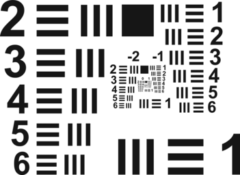
The resolution of a system may be experimentally determined using an optical target such as the USAF 1951 optical calibration target (Department of Defense, Citation1959), shown in Figure . This target consists of groups containing six line patterns per group. Each line pattern has progressively smaller line widths and line spacing. When the individual lines can no longer be distinguished, the group and pattern numbers represent the resolution limit for the system, expressed in terms of mm/lp (lp stands for line-pair). The reciprocal is called the spatial frequency in terms of lp/mm, and relates to the group and pattern numbers as
Optical Design
The following sections outline the process of developing a preliminary design of the scanning telescope and using the ZEMAX software to optimize the design around the desired performance, and to characterize the aberrations due to off-axis imaging.
Optical layout based on on-axis optimization
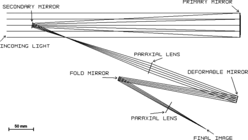
We use an existing basic telescope layout as a starting point in the software design. We choose the basic Newtonian telescope as a starting point for its simplicity and easy scanning of the primary element. A key design consideration is to physically fit the deformable mirror in the optical system. The footprint on the optical breadboard for a deformable mirror is considerably larger than a standard flat mirror due to the size of the mirror housing. The incoming and reflected light at the deformable mirror also must make as small an angle as possible to make most effective use of the deformable mirror stroke and shape correcting capabilities. The protective glass element over the deformable mirror will reflect some of the incident light and a smaller angle will reduce ghosting due to reflections in the final image. The pupil size at the deformable mirror also must match the size of the active reflective surface in order to efficiently utilize the mirror's entire array of actuators.
The design process starts with static (non-scanning) components using paraxial lenses to determine focal distances and general spacing requirements. Paraxial lenses are ideal thin positive lenses that are convenient to use for the initial design (Fischer and Tadic-Galeb, Citation2000). A primary mirror with a 50.8 mm diameter is used according to the resolution calculation. A secondary mirror with 12.7 mm (0.5”) diameter is chosen because this is a common flat mirror size and will block only a small amount of the incoming light. The system is optimized to minimize the maximum wavefront peak-to-valley variation at the image plane, the pupil size deviation from the deformable mirror aperture size of 14 mm, and the difference between the final image size and the CCD array size of 16 mm. The variables for this optimization are the position and focal length of the paraxial lenses as well as the position of the deformable mirror. A limit is also set on the distance to the first paraxial lens from the secondary mirror. This distance must be long enough so that the first lens position will not obstruct the incoming light when scanning the primary mirror. After performing the initial optimization, it is clear in that placing a camera at the final image position will obstruct incoming light when scanning. A fold mirror therefore placed before the second paraxial lens to redirect the light path and place the camera position well out of the way of incoming light. The result is shown in Figure . For this layout, a wavefront error of 0.063λ is achieved on the axis.
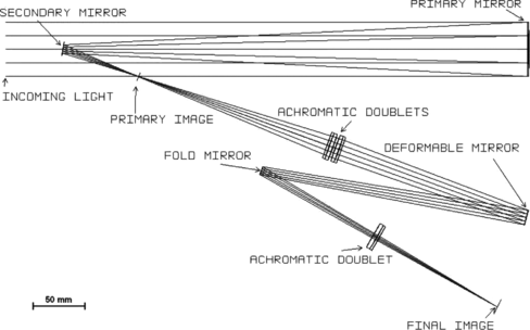
For our laboratory implementation, we used off-the-shelf optical components for quick assembly and lower cost. For this next level of optimization, we used the optimized paraxial design as the starting point. Figure shows the optimized optical layout. The wavefront function yields a peak-to-valley magnitude of 0.186λ of aberration which is below 0.25λ, the diffraction limit for a near-perfect optical system. The optimization results in a deformable mirror pupil diameter of 14.4 mm and a CCD image diameter of 18 mm. While these are not the exact target values, they are close enough that the telescope will operate as expected.
Off-axis aberration
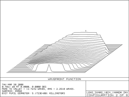
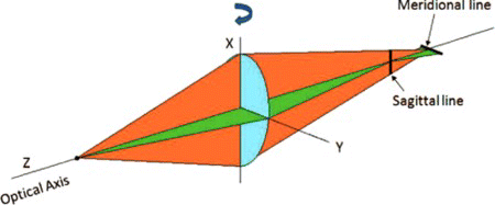
A key requirement for the scanning telescope is that the wavefront aberrations created by off-axis imaging must be within the stroke range of the deformable mirror. The wavefront error corresponding to different tilt angles of the primary mirror is given in Table . This error must be corrected for by the deformable mirror. For example, a 5°horizontal tilt has 12.8 wavelengths of peak-to-valley aberration. At a wavelength of 550 nm, this corresponds to approximately 7 µm of optical path difference and requires a mirror stroke of half the amount (3.5 µm). The wavefront error shape shown in Figure has the characteristic shape of astigmatism. Astigmatism results from rays from the meridional and sagittal planes focusing at different distance from an optical element, as shown in Figure . This difference in focal distance is due to the tilt of the primary mirror, and the magnitude of astigmatism increases proportional to the square of the mirror tilt angle (Fischer and Tadic-Galeb, Citation2000), also seen in Table .
Table 1. Peak-to-valley wavefront error (in wavelengths) for horizontal and vertical mirror tilt
Obscuration effects
When the field of view is on-axis, the secondary mirror is centered directly in front of the primary mirror. As the scan angle of the primary mirror increases, it will eventually move entirely out of the way of the incoming light, as seen in Figure . Initially when determining the resolution, a limit of 3.3 mm/lp is calculated only by considering the aperture diameter of the primary mirror. In reality, the amount of light actually arriving at the primary mirror is equivalent to the surface area of this mirror minus the surface area of the obscuration due to the secondary mirror.
Figure 7 Obscuration blocking incoming light at various field angles. (Figure is provided in color online.).

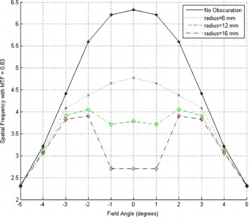
To characterize the degradation of resolution due to obscuration, we use modulation transfer function (MTF) (Boreman, Citation2001), which is the response of an optical system to an input of varying spatial frequencies. We use MTF = 0.83 as the threshold for resolving power (obtained based on on-axis imaging with no obscuration). Figure shows the spatial frequency for MTF = 0.83 at various field angles and different size of the secondary mirror, clearly illustrating the resolution degradation due to obscuration. For the radius of 8 mm, there is approximately a 25% reduction in resolution on-axis. This changes the initial resolution limit calculation from 3.3 mm/lp to 4.4 mm/lp, but it is still well within the acceptable range.
Mirror surface optimization based on Zernike polynomial approximation
With the design of the telescope fixed, we evaluate its off-axis performance by optimizing the deformable mirror surface shape at different scanning angles. We use the built-in optimization in ZEMAX to minimize the wavefront error, with the deformable mirror shape approximated by a 10th order Zernike polynomial (Doyle, Genberg, and Michels, Citation2002).
Table shows the Zernike coefficients at various angles with the resulting wavefront errors. Figure shows the mirror profile necessary for correction at a 5°tilt angle. This profile is the typical saddle profile associated with the correction of astigmatism.
Figure 9 Deformable mirror surface profile at 5°mirror tilt optimized with Zernike polynomial representation.
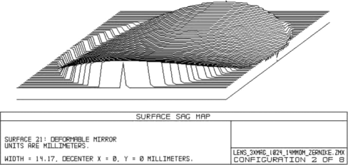
Table 2. Zernike coefficients representing deformable mirror surface and the corresponding wavefront error after correction (in wavelengths)
3. EXPERIMENTAL SETUP AND TEST RESULTS
The scanning telescope design described in the previous section has been tested outdoor for the on-axis performance and in a laboratory setting using two different types of deformable mirrors for the off-axis performance. The actuator voltages are optimized off-line in discrete scanning mirror positions by maximizing the image sharpness metric. During run time, the voltages may be obtained for different scanning mirror positions via interpolation. This section describes the experimental setup and the test results.
Outdoor Testing
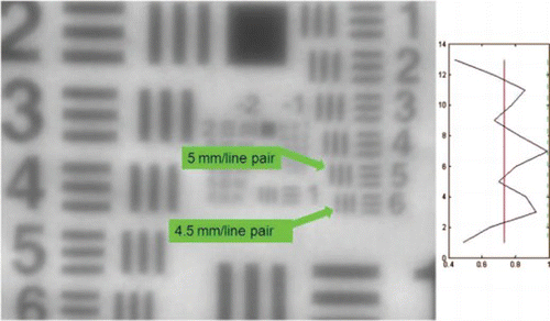
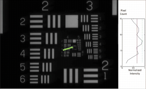
The outdoor testing has only been conducted for the on-axis system with a USAF 1951 optical calibration placed 250 m away. It is immediately evident that atmospheric disturbances are present and cause image variations. We therefore collect a series of shots and only use better images, such as Figure . The bar pattern that just meets the minimum resolution corresponds to 5 mm/lp. The difference from the simulated expectation of 4.4 mm/lp is not surprising due to the atmospheric disturbances and less than ideal lighting conditions. For practical use, additional correction of these disturbances using the deformable mirror may be necessary.
Laboratory Testing and Optimization
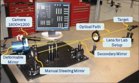
An equivalent telescopic system is built on an optical table indoors. In order to compensate for the reduced target distance, a positive lens with a 600 mm focal length is placed in front of the telescope and an illuminated USAF 1951 optical calibration target is placed at the focal plane of the lens. This setup collimates the incoming light creating the illusion that the target is equivalently at a great distance. During testing, it is necessary that the distance from the primary mirror to the positive lens and from the lens to the target be the same no matter what angle the primary mirror is at. To accomplish this, the telescope assembled on the breadboard is allowed to pivot about the axis of the primary mirror while attached to the optical table. The mirror can pivot on the same axis to point at the target and acquire the test images. This is shown in Figure from the view of looking down on top of the optical table.
Image Sharpness
As the primary mirror is scanned to off-axis angles, there is obvious degradation in the image quality due to the aberrations introduced into the system. In order to quantify the level of image degradation, a sharpness metric is used. This calculation of sharpness S is given as
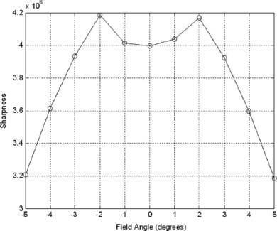
While there is not an exact correlation between the sharpness calculation and the MTF, they are both a measure of the quality of the image. Figure is a plot of the image sharpness values recorded at 1°increments for field angles between −5°and 5°. This curve is comparable to the ZEMAX simulation data found in Figure . In particular it matches well to simulations with larger obscuration. It is clear by the experimental data that there is image degradation over field angles when the obscuration is in the way. The fact that there is slightly more degradation in the laboratory setup is consistent with the resolution seen in outdoor experiments.
Deformable Mirror Surface Optimization
Even though we have determined through simulation the mirror surface shapes required to remove the aberrations at each scanning angle, achieving those shapes is not easily done. The mirror response to the input actuator voltage is nonlinear and highly coupled. Different deformable mirrors also have varying rigidity in the mirror surface materials, causing different mirror shapes under the same actuator voltages. We therefore use a gradient ascent method based on the sharpness metric (as in Potsaid and Wen, Citation2008). The basic algorithm for the actuator voltage update is
Optimization and Resolution Test Results for AgilOptics Mirror
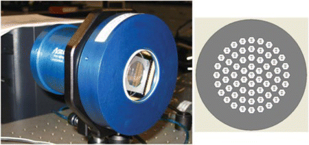
Two different deformable mirrors are tested in the telescope setup. The first is a 61-actuator, 6 µm stroke mirror manufactured by AgilOptics (Figure ). Input voltages on this mirror range from 0 to 160 volts. Actuators on this mirror can only pull the mirror surface down so it is necessary to bias the input voltages at 80 volts in order to set the mirror near the center of its dynamic range. This way the actuators can push up by lowering the applied voltage. Once the bias is set, the telescope is aligned and focused on axis. Images are acquired with a QImaging Retiga 2000 R cooled monochromatic camera with 1600 × 1200 resolution. The on-axis resolution is characterized based on the USAF 1951 target. The smallest resolvable pattern is group 6 pattern 4, which corresponds to 11 µm/lp.
Figure 13 AgilOptics deformable mirror and 61-actuator footprint. (Figure is provided in color online.).
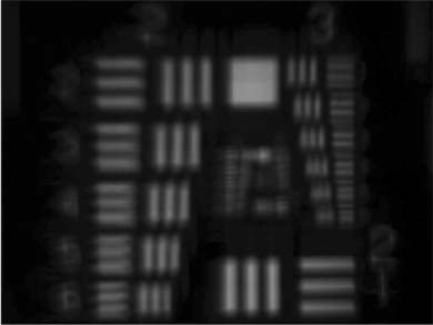
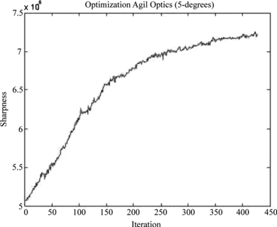
The mirror surface optimization is performed at 2°interval for the scanning mirror position. Note, that a 2°rotation of the telescope results in a 1°tilt of the primary mirror. Figure shows the uncorrected image at a mirror tilt of 5°, which is highly blurred. The optimization iteration continues until the resolution is as good as the on-axis resolution or until the actuator voltages reach their limits and further correction is no longer possible. Figure shows the optimization results at 5°mirror tilt. Ideally, this plot would show an increase in sharpness after every iteration but it sometimes drops a small amount. This is due to the approximation in the gradient computation and sensitivity of the system to fluctuation in light which shows up as noise.
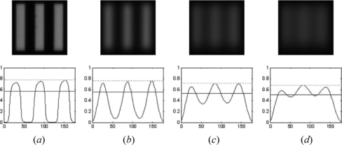
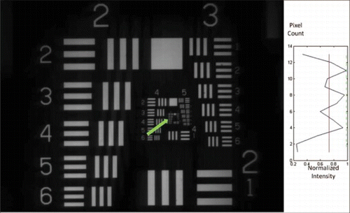
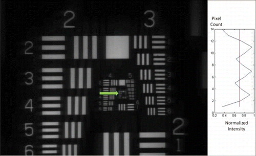
Figures and show the corrected images at 5- and 6-degree mirror tilt, respectively. Accompanying each image is a plot of the intensity (horizontal axis) of the bar pattern pointed by the arrow versus the pixel number (vertical axis), with the maximum intensity normalized to 1. If the peak-to-trough variation is large enough (with the trough below normalized intensity 0.74, indicated by the solid line), then the pattern is considered to be resolvable. The pattern pointed to by the arrow corresponds to the smallest resolvable bar pattern based on this intensity criterion.
Up to the 5°tilt, as shown in Figure , the smallest resolvable bar pattern on the USAF 1951 target is at least group 6 pattern 4. At 6°tilt, shown in Figure , the smallest resolvable bar pattern degrades to group 6 pattern 3, or 12.5 µm/lp. We therefore consider the correctable scanning range to be ±5°. At 6°, the image not only has decreased in resolution but many of the actuators have reached their voltage limits and can provide no further correction. From Table , 6°mirror tilt results in 17.7 wavelengths of aberration. Ideally, the deformable mirror has a maximum stroke of 6 µm, and should be able to correct for 21.8 wavelengths of aberration (based on the 550 nm wavelength). In reality, the actual usable stroke range depends on the surface shape and the residue internal stress in the particular mirror.
With a mirror tilt of ±5°, a field angle of 10°can be acquired in both directions resulting in a 20°horizontal field of view. This overall horizontal field of view is 40.8 times larger than an equivalent stationary telescope with the same resolution. If the experiments are expanded to allow vertical mirror tilt, according to the simulation results in Table , the expected rectangular field of view maintaining the same 4:3 aspect ratio would be 16°horizontally and 12°vertically. This corresponds to horizontal and vertical fields that are 32.7 times as large as the original field size or a field area that covers 1,064 times the area of an equivalent stationary telescope.
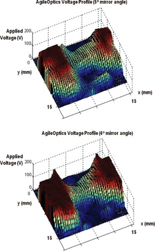
Figure shows plots of the actuator voltages across the surface of the mirror for five- and six-degree mirror tilt. These profile show the characteristic saddle profile of the astigmatism aberration, and roughly match the shape in Figure which is a Zernike representation of the corrective surface. Note the actuator saturation in the 6°tilt case resulting in reduced resolution.
Optimization and Resolution Test Results for Mirao–52d Mirror
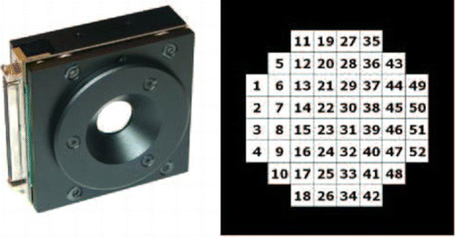
For the eletromagnetic mirror, we use Mirao–52d from Imagine Eye (Imagine Eyes, Citation2010), shown in Figure . It has 52 actuators capable of ±50 µm stroke with the applied voltage range for each actuator ±1 V (Sabesan, Ahmad, and Yoon, Citation2007). For the on-axis image, the resolution limit is group 6 pattern 3 (or 12.5 µm/lp), which is less than the resolution obtained by the AgilOptics mirror. Mirao has 52 actuators versus the 61 actuators of AgilOptics. The reduced image quality may be due to the coarser actuator layout or slight misalignments in the system.
Figure 19 Imagine eyes Mirao 52d deformable mirror and 52-actuator footprint. (Figure is provided in color online.).
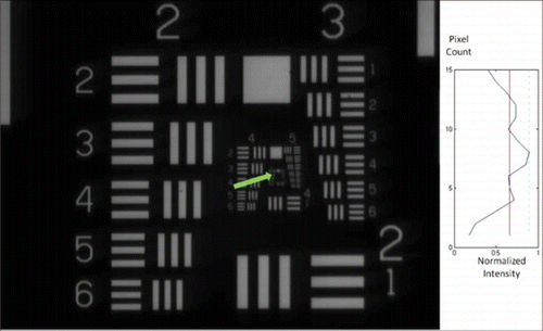
For a mirror tilt of 10°, as shown in Figure , the mirror is still able to meet the resolution limit. At 11°, as shown in Figure , the resolution limit drops to group 6 pattern 2 (14 µm/lp). We therefore consider the correctable range to be ±10°. These results are consistent with ZEMAX simulations. In Table , 10°of horizontal tilt produces 44 wavelengths of aberration, or equivalently 24 µm of actuator stroke. According to the manufacturer documentation, the maximum peak to valley correction for astigmatism is 30 µm. For this version of Mirao, the actuator coils overheat if they are held too long at 0.5 V or greater, so an artificial limit of 0.4 V has been imposed. This 40% of stroke reduction results in 12 µm of stroke or the same 24 µm of peak to valley correction that we have observed.
The Mirao mirror can maintain the same on-axis resolution over ±10°of horizontal mirror tilt. This results in a horizontal field angle of 40°, which is just over 80 times larger than a stationary telescope with the same resolution. If this experimental setup were modified for vertical mirror tilt, simulation results from Table indicate that it is possible to expand the rectangular field of view with a 4:3 aspect ratio to 36°horizontally and 24°vertically, corresponding to a field area 4,264 times larger than a stationary telescope.
Performance Summary
The two mirrors tested in this study and their performance in the scanning telescope are summarized in Table . The key differentiating factor is the stroke range, and to a lesser extent the number of actuators. With the AgilOptics deformable mirror, the field of view can be increased to 40.8 times of the stationary case. With the large stroke of the Imagine Eyes mirror, the field of view can be increased to 81.6 times while maintaining the on-axis resolution.
Table 3. Summary of experimental results
4. SUMMARY AND FUTURE WORK
We have shown both by simulation and experimental methods that it is possible to increase the field of view in a telescope by scanning the primary mirror and correcting for the aberrations with a deformable mirror. The simulation results match the experimental performance of the two deformable mirrors that were tested. With the AgilOptics deformable mirror, the field of view can be increased to 40.8 times of the stationary telescope, and with the large stroke of the Imagine Eyes Mirao mirror, the field of view can be increased by 81.6 times, while maintaining the on-axis resolution.
For our current system, the optimization of the deformable mirror at a given field position can take anywhere from an hour to half a day to complete. This is due largely to the use of the MATLAB optimization routine and the communication delay between MATLAB and the camera. We anticipate a significant reduction of the optimization time once this architecture is improved. Once the mirror optimization time is reduced, it is advantageous to perform the optimization on as many discrete field positions as possible for improved system performance.
The concept of using high speed scanning to widen the field of view may be extended to other applications. For example, the same principle in reverse may be used for a wide field display, though the frame rate requirement places challenging demands on the dynamic response of the deformable mirrors.
ACKNOWLEDGMENTS
The authors would like to thank Dr. Mark T. Gruneisen for his groundbreaking work in SLM adaptive optics scanning telescopes and for lab tours, which provided motivation for this research activity. This work is supported in part by the Center for Automation Technologies and Systems (CATS) under a block grant from the New York State Foundation for Science, Technology and Innovation (NYSTAR), and in part by the National Science Foundation (NSF) Smart Lighting Engineering Research Center (EEC-0812056). The authors would also like to thank Imagine Eyes, Inc. for providing a demonstration Mirao 52-d deformable mirror for testing, and Thorlabs, Inc. for providing various optical components used in this work.
REFERENCES
- Boreman , G. D. 2001 . Modulation transfer function in optical and electrooptical systems . Bellingham , WA : SPIE Press .
- Department of Defense . 1959 . Photographic lenses. MIL-STD-150A.
- Devaney , N. , D. Coburn , C. Coleman , J. Dainty , E. Dalimier , T. Farrell , D. Lara , D. Mackey , and R. Mackey . 2007 . Characterisation of MEMs mirrors for use in atmospheric and ocular wavefront correction. In Proc. of SPIE Vol. 6888: MEMS Adaptive Optics II, pp. 688802-1–688802-10.
- Doyle , K. B. , V. L. Genberg , and G. J. Michels . 2002 . Integrated optomechanical analysis . Bellingham , WA : SPIE Press .
- Fischer , R. E. and B. Tadic-Galeb . 2000 . Optical system design . New York : McGraw-Hill .
- Gruneisen , M. T. , R. C. Dymale , J. R. Rotge , L. F. DeSandre , and D. L. Lubin . 2005a . Compensated telescope system with programmable diffractive optic . Optical Eng. 44 ( 2 ): 023201 .
- Gruneisen , M. T. , M. B. Garvin , R. C. Dymale , and J. R. Rotge . 2005b . Agile-field telescope system with diffractive wavefront control . In Advanced wavefront control: methods, devices, and applications III. Proceedings of the SPIE , eds. M. T. Gruneisen , J. D. Gonglewski , and M. K. Giles , Presented at the Society of Photo-Optical Instrumentation Engineers (SPIE) Conference, vol. 5894, pp. 345–350 .
- Guestrin , C. , F. Cozman , and M. Simoes . 1998 . Industrial applications of image mosaicing and stabilization . In Proceedings of Second International Conference on Knowledge-Based Intelligent Electronic Systems , vol. 2 , pp. 174 – 183 .
- Hardy , J. W. 1998 . Adaptive optics for astronomical telescope . New York : Oxford University Press .
- Imagine Eyes . 2010 . http://www.imagine-eyes.com (accessed July 2, 2010).
- James , S. A. 2007 . A small-scale 3D imaging platform for algorithm performance evaluation. Master's thesis, Air Force Institute of Technology, Wright-Patterson Air Force Base, OH.
- Kauchak , M. 2007 . New eye in the sky . Military Geospatial Technology 4 ( 3 ): 5 – 7 .
- Liang , J. , D. Williams , and D. Miller . 1997 . Supernormal vision and high-resolution retinal imaging through adaptive optics . Optical Society of America 14 ( 11 ): 2884 – 2892 .
- Martinez , T. , D. Wick , and S. Restaino . 2001 . Foveated, wide field-of-view imaging system using a liquid crystal spatial light modulator . Opt. Express 8 ( 10 ): 555 – 560 .
- Muller , R. A. and A. Buffington . 1974 . Real-time correction of atmospherically degraded telescope images through image sharpening . J. Opt. Soc. Am. 64 ( 9 ): 1200 .
- Potsaid , B. , Y. Bellouard , and J. Wen . 2005 . Adaptive scanning optical microscope (ASOM): A multidisciplinary optical microscope design for large field of view and high resolution imaging . Opt. Express 13 ( 17 ): 6504 – 6518 .
- Potsaid , B. , F. Finger , and J. Wen . 2009 . Automation of challenging spatial-temporal biomedical observations with the adaptive scanning optical microscope (asom) . Automation Sci. Eng., IEEE Trans. 6 ( 3 ): 525 – 535 .
- Potsaid , B. and J. Wen . 2008. Adaptive scanning optical microscope (ASOM): Large field of view and high resolution imaging using a MEMS deformable mirror. J. Micro/Nanolithography, MEMS, and MOEMS (JM3), Special Issue on Silcon-Based MOEMS and Their Applications 7(2):021009-1–021009-10.
- Sabesan , R. , K. Ahmad , and G. Yoon . 2007 . Correcting highly aberrated eyes using large-stroke adaptive optics . J. Refractive Surgery 23 ( 9 ): 947 – 952 .
- Wick , D. , T. Martinez , S. Restaino , and B. Stone . 2002 . Foveated imaging demonstration . Opt. Express 10 ( 1 ): 60 – 65 .
- Xinetics ( 2010 ). http://www.as.northropgrumman.com/businessventures/xinetics/index.html (accessed July 2, 2010) .
