
ABSTRACT
This article presents a compact multi-spectral lens array and describes its application in assisting color-blindness. The lens array consists of 9 microlens, and each microlens is coated with a different color filter. Thus, it can capture different light bands, including red, orange, yellow, green, cyan, blue, violet, near-infrared, and the entire visible band. First, the fabrication process is described in detail. Second, an imaging system is setup and a color blindness testing card is selected as the sample. By the system, the vision results of normal people and color blindness can be captured simultaneously. Based on the imaging results, it is possible to be used for helping color-blindness to recover normal vision.
Nomenclature
| mW/cm2 | = | the exposure intensity |
| min | = | Time unit: minute |
| s | = | Time unit: second |
| °C | = | Celsius temperature |
| µm | = | length unit: micro meter |
| nm | = | length unit: nano meter |
| RPM | = | Rotational speed per minute |
| B | = | Blue color |
| G | = | Green color |
| R | = | Red color |
| C | = | Cyan color |
| O | = | Orange color |
| V | = | Violet color |
| Y | = | Yellow color |
| IR | = | Infrared |
1. Introduction
Multi-spectral imaging[Citation1,Citation2] is an important technology to realize accurate spectral separation and obtain image information of different frequency bands. Combined with digital image processing technology, it can be used in many areas such as high-precision color reconstruction[Citation3Citation4Citation5], biomedical imaging,[Citation6Citation7Citation8Citation9] and so on.
However, current multi-spectral cameras are larger than normal cameras, because they usually are equipped with a mechanism for changing the spectral transmittance, such as a filter wheel[Citation10] or a liquid crystal tunable filter[Citation11]. What’s more, these cameras could only capture one image of a certain band at a time, so it is inconvenient to operation. Therefore, it is desirable to design a more integrated and smarter multi-spectral imaging system.
In this article, we present a new method which consists of a photoresist lithography process[Citation12] and thermal reflow process[Citation13] to integrate the multi-channels filter with a microlens array on one substrate. The structure can capture the images for different bands simultaneously, so it can be considered as a compact multi-spectral lens. It has nine optical units corresponding to red, orange, yellow, green, cyan, blue, violet, near-infrared, and whole visible band, respectively.
In order to investigate the imaging effects of the lens, a multi-spectral imaging system was setup. Compare to current multi-spectral cameras, it is more compact and meets the trend of miniaturization requirement. Additionally, the system could get more color information of the object owing to its nine independent imaging units. Moreover, the system could work in visible bands and near-infrared bands simultaneously, which is beneficial to extend its application range.
The most important application of multi-spectral imaging is revealing the hidden information that is hardly observed by naked eyes or an ordinary camera. In this article, a color blindness test card was selected as the observing object. The imaging results reflected both the normal vision and color-blindness’s vision. So, it is a probable method to help blindness recover normal vision if the image of a certain band is projected on color-blindness’s eyes.
2. Design and fabrication of multi-spectral lens
The fabricate process is divide into 3 main parts. First is the fabrication process of a light blocking layer which is used for reducing the influence of incident stray light. Second is the fabrication process of the multi-channel filter. The last is the fabrication process of the microlens array.
2.1. Design and fabrication of the light blocking layer
Because the substrate of this multi-spectral lens is transparent and there is light transmission space between the two adjacent microlenses, stray light could go through the substrate directly and be accepted by the CMOS sensor. It will lower the imaging quality and bring serious background noise. To reduce the influence of stray light, a light blocking layer is needed between the microlenses.
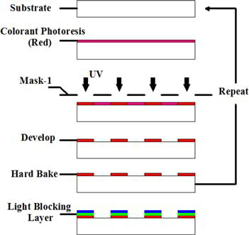
shows the fabrication process of the light blocking layer. This method is normally used in Liquid Crystal Display (LCD) manufacturing. Detail steps are as follows: glass substrate was cleaned by acetone, rinsed with isopropanol (IPA), and dehydrated in the oven prior to use. Then, the colorant photoresist (red) with thickness of about 1 µm was spin-coated on the substrate. After baked in the oven to fully remove the residual solvent in the film, the film was exposed to UV light under the cover of the prepared mask. The transparent part of the mark is a 3 × 3 circular array and each circular diameter is 900 µm. Spacing of each circular is 1.6 cm × 1.4 cm. In this step, the exposure duration and intensity are 12 s and 20 mW/cm2. After developing in the diluent KOH developer, the first anti-interference layer was achieved. Finally, the film was followed by a hard bake process at 230°C for duration of 20 min in order to cure the photoresist completely. The performance of fully cured colorant photoresist is very stable and it will not affect the subsequent fabricate process. These process need to be repeated 2 times until blue and green colorant photoresist were fabricated onto the same position. The overlap layer appeared as black which can absorb more than 95% visible light. In the next section, the multi-channel filter and microlens will be produced at the corresponding transparent circular area.
Figure 1. The fabrication process of the light blocking layer.
2.2. Design and fabrication of the multi-channel filter
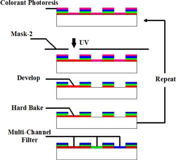
shows the fabrication process of the multi-channel filter. This process is very similar to the previous. Just need to pattern other colorant photoresist on the specific transparent circular area made above. For fabricating nine channel multi-spectral filters (red, orange, yellow, green, cyan, blue, violet, near-infrared bands, and opaque area), eight different colorant photoresist are needed. However, only the red, green, blue, and yellow photoresist could be provided directly by the merchants. The other colorant photoresist have to be made by mixing the photoresist of the three primary colors (red, green, and blue) in appropriate proportion. For example, the orange colorant photoresist is made by mixing red and green colorant photoresist according to the volume ratio of 1:1; the cyan colorant photoresist is made by mixing green and blue colorant photoresist according to the volume ratio of 1:1; the violet colorant photoresist is made by mixing red and blue colorant photoresist according to the volume ratio of 1:2; the infrared section is made by a combination of three basic colorant photoresist overlapping together. The required lithography parameters of this section are the same as previous.
Figure 2. The fabrication process of the multi-channels filter.
2.3. Design and fabrication of the microlens
In this section, the microlens array should be fabricated and integrated on the multi-channel filter made above. Theoretically speaking, for a single lens imaging system, the thinner lens will bring about smaller geometrical imaging aberration and the larger lens aperture could bring about less diffraction effect. Therefore, making the aperture and curvature radius of each microlens as large as possible is an inevitable requirement to ensure imaging quality. However, limited by the thickness of the AZ4620 photoresist and the process of thermal reflow, it is hard to fabricate a large lens. Therefore in this article a set of optimal parameters are chosen according to the experimental experience.
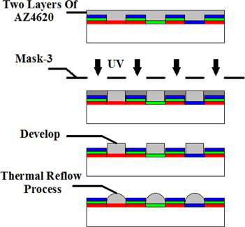
The process is shown in . The photoresist of AZ-4620 was spin-coated on the multi-channel filter substrate made above twice in order to make the photo-resistant layer thick enough and each spin-coating parameter is 1200 RPM for 45 seconds and then 2000 RPM for 30 seconds. After coating, the thickness of photoresist can reach about 20 µm. The temperature of pre-bake was set to 90°C for 4 minutes to fully remove the residual solvent in the film. After preparing the layer of photoresist, the sandwich was exposed to UV light under a prepared mask. The opacity part of the mask is a 3 × 3 circular array with diameter of 700 µm. The exposure duration and intensity are 12 s and 20 mW/cm2. Following the above process, the sandwich was put into the diluent AZ-400k developer for developing. After developing, the substrate was rinsed with deionized water to remove the remaining developer and then dried by nitrogen. Lastly, the sample was put on a smooth hot stage for executing the thermal reflow process. After heating at 128°C for 115 s, the microlens array structures were fabricated on the multichannel filter.
Figure 3. The fabrication process of the microlens array.
2.4. Fabrication results
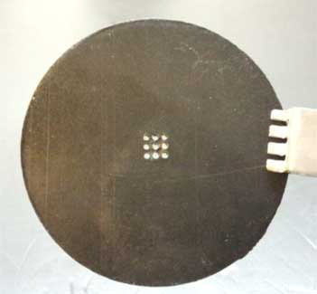
After the whole processes, the compact multi-spectral lens was fabricated successfully. The fabricated sample was shown as . From the figure, it is can be seen that a 3 × 3 microlens array was integrated with the multi-channels filter and the nine optical units correspond to red(1), orange(2), yellow(3), green(4), cyan(5), blue(6), violet(7), whole visible(8), and near-infrared(9) bands, respectively. The position of microlens matched with the filter precisely.
Figure 4. The sample of multi-spectral lens.
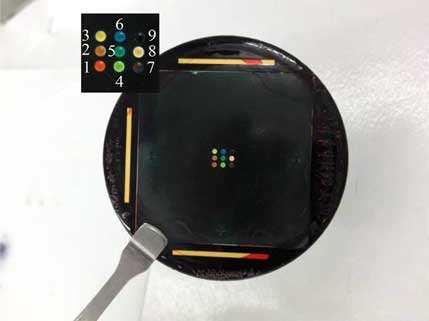
The profile of lens was measured by the XP-1 profile detector (Ambios Technology, USA) and the diameter of each lens is about 960 µm which was slightly larger than the diameter of the circular mask patterns. The lens height is about 23 µm and the focal length is about 5 mm. The imaging results shown in Section 3 illustrate that the uniformity of the lens array is fine.
shows the measured transmission spectrum of visible bands multichannel filter. The results explain the filter has the expected filter performance for the red, green, and blue bands. shows the measured transmission spectrum of the orange, yellow, cyan, and violet filters. The orange and cyan filters could meet the requirement basically, but the transmittance curve of violet filter is not completely identical with the violet band, so it needs to be improved in the future. From the transmission spectrum of the yellow band in , we can see that the filter can only cut off most of the blue and purple light but is invalid for red light. It means that the filter has not accurate selectivity for yellow band and it can be improved by changing fabrication method, such as a vacuum coating process. shows the measured transmission spectrum of the filter unit for the near-infrared band. From the figure, it is seen that the microlens 9 has a high transmittance in the near-infrared band (800–1200 nm) and is opaque for the visible band.
Figure 5. The transmission spectrum of red, green, and blue filter.
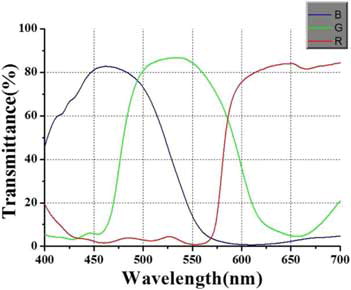
Figure 6. The transmission spectrum of orange, yellow, cyan, and violet filter.
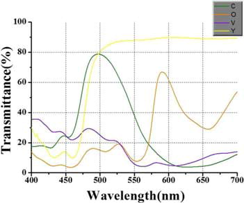
Figure 7. The transmission spectrum of near-infrared filter.
3. The experiment setup and results
3.1. The experiment setup
To test the optical property of the microlens array, a multi-spectral imaging system was set up. shows that the system consists of a light source, an object, the multi-spectral lens, a CMOS imaging circuit, and a computer. The size of the CMOS is 1/2.3 inch, the resolution and the pixel size is 3856 × 2764 and 1.67 µm × 1.67 µm, respectively. The nine microlenses could totally and evenly utilize the CMOS pixels. Because each microlens is close to the adjacent one, crosstalk with the adjacent unit is inevitable and it will result in ghost image problem. Therefore, a signal separator diaphragm should be inserted behind the lens. In order to eliminate the interference between different channels totally, to our system, the thickness of the separator should be longer than 3 mm. As shown in , the separator consists of a 3 × 3 holes array and its material is ABS plastic board. The holes array was fabricated by laser drilling technology and their position can be accurately matched with the microlens array.
Figure 8. The setup of the multi-spectral imaging system.
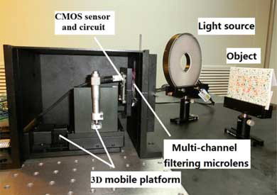
Figure 9. The signal separator diaphragm.
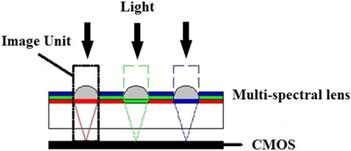
shows the principle of the imaging process. In the system, each microlens and its color filter is considered as an image unit, and the image units work independently. As a result, the object was imaged and captured by the CMOS in different channels. The images were sent to a computer for processing and display.
Figure 10. The principle of imaging.
3.2. Imaging results
The system was used to image the color blind testing cards. These cards contain different patterns in different color bands. People with color deficient would only discern certain patterns.
is the original image of the test card captured by a commercial digital camera. show the images captured by the multi-spectral imaging system under a full-spectrum light source. After focus, nine independent images are obtained simultaneously by the optical units of the multi-spectral lens. The results provide clear and separated images of the observing object and each separated image corresponds to a different band. The -8 is captured by the transparent unit and in which the normal vision pattern of “an ox” can be distinguished. In the -1(red), 2(orange), and 3(yellow), the “ox” was displayed more clearly. However, the displayed pattern in -4(green), 5(cyan), 6(blue), and 7(violet) is a “chicken” and these images are similar with the vision results of protanopias color blindness who was insensitive to red light. In -9(infrared), a monochrome image was obtained. Most of the color details were missing, but a black contour of the “ox” could be seen.
Figure 11. (a) The original image of the color blindness test card captured by a commercial digital camera. (b) The image captured by the multi-spectral imaging system. (c1) The processed image of 11(b)-1 after discoloration. (c2) The processed image of 11(b)-6 after discoloration.
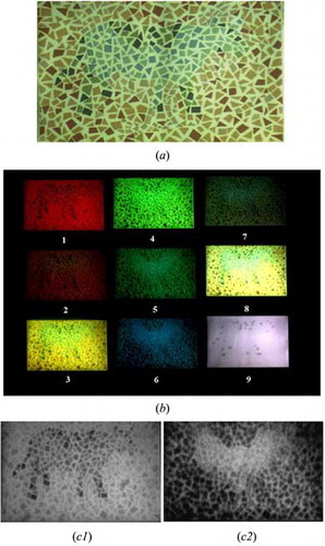
The imaging results illustrate the multi-spectral lens could work in both the visible and the near-infrared bands as expected and the hidden image information of different bands can be extracted successfully. The vision results of both normal people and color blindness can be obtained by the imaging system.
Through the contrast preserving discoloration method[Citation14], we change the -1 and -6 to monochrome images as shown in and . Using this method, the hidden image information in the test card could be extracted and highlighted. Furthermore, the monochrome images can be changed to the sensitive bands of color blindness by use of the image process algorithm. Then it could help the color blindness to perceive normal vision. Thus, this system has great potential to assist color blindness.
4. Further discussions
Nearly all color blindness can feel the color information, but cannot distinguish them. They have different troubles – most cannot distinguish between reds and greens in dim light; some cannot separate blues from yellows; and a very small group called as monochromatism can only see black and white[Citation15]. Currently, there is no effective method to cure color blindness completely. Colored filters or contact lenses are available to help them increase brightness and recover part of normal vision in certain circumstances[Citation16]. But there is still no one product can fit all different chromatism.
In this article, we present a novel multi-spectral lens. Although the color photoresist filter used in this article is a broadband filter, we can design a different optical thin film according to the different types of color blindness and through a vacuum coating method integrate the needed film on the substrate. Moreover, due to the multi-channels filter, the system could get more color information from the object. Based on the rich color information, we can reduce or enhance certain color intensity according to the demand of chromatism by using an image process algorithm. Thus, this system has the potential for color-blindness auxiliary correction.
5. Conclusions
This article presents a novel method of integrating the microlens structure with the multichannel filter on one substrate based on the micro fabrication technique. By this method, a compact multi-spectral lens was developed. The structure has several optical units, and each unit can capture the information for a certain band. The fabrication details and key steps have been discussed. Based on the lens, a multi-spectral imaging system was set up. The system was used to take images of a color blindness test card. The imaging results illustrate the multi-spectral lens has the expected filtering and imaging properties. By the system, the vision results of normal people and color blindness can be captured simultaneously. Through a contrast preserving discoloration method, the hidden image could be extracted and highlighted. Due to the high degree integration of our multi-spectral lens, in the future, it could be integrated into a head mounted display system. Thus, the lens has great potential for color blindness auxiliary treatment, finding hidden information, and so on.
References
- Petteri, T. Multispectral imaging. 2007, Course Project for Imaging and Display Technology in Helsinki University of Technology.
- Shogenji, R.; Kitamura, Y.; Yamada, K.; Miyatake, S.; Tanida, J. Multispectral imaging using compact compound optics. Opt. Exp. 2004, 12, 1643–1655.
- Sitnik, R.; Krzesłowski, J.; Mączkowski, G. Archiving shape and appearance of cultural heritage objects using structured light projection and multispectral imaging. Opt. Eng. 2012, 51, 021115.
- Murakami, Y.; Obi, T.; Yamaguchi, M.; Ohyama, N. Nonlinear estimation of spectral reflectance based on Gaussian mixture distribution for color image reproduction. Appl. Opt. 2002, 41, 4840–4847.
- Yamaguchi, M.; Teraji, T.; Ohsawa, K.; Uchiyama, T.; Motomura, H.; Murakami, Y.; et al. Color image reproduction based on the multispectral and multiprimary imaging: experimental evaluation. Proc. SPIE. 2002, 4663, 15–26.
- Paquit, V.C.; Tobin, K.W.; Price, J.R. 3D and multispectral imaging for subcutaneous vein detection. Opt. Express. 2009, 17, 11360–11365.
- Berezhnyy, I.V.; Berezhna, S.Y. Fast multi-spectral imaging technique for detection of circulating endothelial cells in human blood samples. Journal of Biomedical Optics. 2012, 17, 081404.
- Chung, S.; Fried, D.; Staninec, M.; Darling, C.L. Multispectral near-IR reflectance and transillumination imaging of teeth. Biomed Opt. Express. 2011, 2, 2804–2814.
- Pelagotti, A.; Ferrara, P.; Pescitelli, L.; Delfino, C.; Gerlini, G.; Piva, A.; et al. Multispectral imaging for early diagnosis of melanoma. Proc. SPIE. 2013, 8668, 86684AK.
- Eichenholz, J.M.; Barnett, N.; Juang, Y.; Fish, D.; Spano, S.; Lindsley, E.; et al. Real time megapixel multispectral bioimaging. Proc. SPIE. 2010, 7568, 75681 L.
- Hardeberg, J.Y.; Schmitt, F.; Brettel, H. Multispectral color image capture using a liquid crystal tunable filter. Opt. Eng. 2002, 41, 2532–2548.
- Sabnis, R.W. Color filter technology for liquid crystal displays. Displays 1999, 20, 119–129.
- Popvic, Z.D.; Sprague, R.A.; Connel, G.A.N. Technique for monolithic fabrication of microlens arrays. Appl. Opt. 1988, 27, 1281–1284.
- Lu, C.; Xu, L.; Jia, J. Real-time contrast preserving decolorization. SIGGRAPH Asia 2012 Technical Briefs, Singapore, November 28-December 1, 2012, ACM, Article No. 34.
- Wong, B. Color blindness. Nature Methods 2011, 8, 441.
- Taylor, D.E. Eyeglasses for improved visual contrast using hetero-chromic light filtration. US Patent 4,300,819, 1981.