
 ?Mathematical formulae have been encoded as MathML and are displayed in this HTML version using MathJax in order to improve their display. Uncheck the box to turn MathJax off. This feature requires Javascript. Click on a formula to zoom.
Abstract
In this work, we report experimental results of a proposed gear system for optimization of phase shifts used for extraction of phase between a reference and a test object in a Double Aperture Common Path Interferometer. The electromechanical approach is designed to increase the precision and control of automated transverse translation of a diffraction grating to obtain equidistant displacements, typically carried out manually. Calculations and analytics for the design and operation of the mechanical gear system are presented. The experimental results demonstrate significant error minimizing for equally spaced phase shifts compared to a previously reported implementation of our research group. The proposed system represents a reliable and low-cost implementation to improve the obtaining of suitable interferogram captures for equally spaced phase-shifting interferometry techniques.
1. Introduction
Nowadays, optical systems are widely used in different application fields such as industry,[Citation1] medicine,[Citation2] and archeology,[Citation3] among others. The optical instrumentation allows direct and indirect quantification of fundamental measurable variables such as refractive index, contour, stretching, mechanical vibrations, and displacement,[Citation4–7] leading to development of complex systems and novel techniques for noninvasive measurement, monitoring, or detection of physical, chemical and biological variables with optical interrogation. In this regard, optical interferometry has been of persistent interest for high resolution optical sensing through the evaluation of the phase difference between two light beams,[Citation8] which contains the information on the measured parameter. For this purpose, interferometric implementations require robustness, high precision, and stability along with algorithms in charge of data computing capable to minimize external noise issues and instability factors, typical of optical experimentation. In this regard, the double aperture common path interferometer (DACPI) is a 4f optical system that allows the phase comparison between a reference window and other containing a test object.[Citation9–11] Considering the proper dimensions and distances, the light from the two windows interferes by means of a diffraction grating.[Citation9] The interference pattern is captured and digitally processed with each transversal displacement of the grating to integrate a set of interferograms. Then, the phase shift is calculated by an algorithm to determine the phase difference between the window objects, where the change in a variable associated with a window object can be determined by the phase difference variation.[Citation12] Moreover, different computational algorithms have been reported to analyze the interference patterns, which differ from each other in the parameters to be considered for the phase extracting such as number of fringes, equidistance of the phase shifts, and complexity of the patterns. Thus, some reliable phase extraction methods require equally spaced phase shifts. As a result, accuracy of equidistant phase shifting between captured interferograms with minimal error must be ensured. Typically, the mechanical methods for phase shift interferometry use advanced control systems based on electronic drivers and piezoelectric motors,[Citation13] which provide high sensitivity shifting but at the expense of high cost of implementation, use of special equipment, and exhaustive calibration. Conversely, the use of mechanical design and additive manufacturing allows the possibility to fabricate translation systems with accuracies comparable to the standards of commercialized devices, with the advantage of reducing costs as well as adjustable design for specific requirements. Advances in CAD/CAM 3D printing technologies have enabled precise building of mechanical systems and components for specific applications with the ability to achieve effective mechanical simulation before the manufacturing process.
In this work, is proposed an electromechanical grating translation system for a DACPI, using a gear system with a transmission ratio of 1 to 5 fabricated by 3D printing. The proposed approach is used to obtain equally spaced phase shifts to allow the application of algorithms that improve the precision when extracting the phase difference between a test object and a reference. The reported system is capable of automatically generating steps as well as real-time calculation of the existing phase between captured interferograms. Analytical and experimental results are presented.
2. Materials and methods
2.1. DACPI operating principle
DACPI is a 4f telemetric imaging system based on two windows located in the object plane, a diffraction grating located in the Fourier plane, and an image capture system in the image plane.[Citation11,Citation14] The experimental setup of the DACPI interferometer is shown in . A collimated light beam propagates parallel through the apertures to coincide with a lens on a diffraction grating. The election of the size and separation of the windows allow the beams to interfere, forming fringe patterns which are captured by a CCD using an optical array. The interference fringes are obtained as a result of a transparent test object placed in front of one of the windows while no object is placed in the other.
Figure 1. Basic schematic arrangement for a DACPI, L1 and L2 are positive lenses of focal length f, is the distance between the centers of the window.
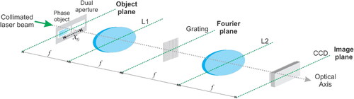
Then, while in one window the beam propagates through free space, in the other window the light passes through a phase object generating an interference pattern whose phase difference between is determined by the object and a reference, given by:[Citation1–7,Citation11,Citation13–22]
(1)
(1)
where
is the light intensity due to the superposition of fields of order
and order
from of reference and probe fields, the terms
and
are known as background and modulation light respectively while
is the phase difference between the probe object
and the reference
and
is the added phase. The change in phase difference can be associated with the variation in the parameter of the test object. Different methods for analytical calculation of the phase difference value such as the Fourier transform method or the phase shift method are used. The Fourier transform method requires a single interference pattern, although it must have a minimum level of noise and proper filtering. On the other hand, the phase shift method introduces phases to the interference pattern and uses algorithms to determine the original phase, even in the presence of moderate levels of signal noise. The increase of
in the original pattern is carried out by transversal displacement to the optical axis of the grating,[Citation22,Citation23] where, the number of displacements and captured fringe patters is the same, given by:[Citation4,Citation24,Citation25]
(2)
(2)
where
is the period and
is the linear displacement of the grating, respectively.
There are robust algorithms for high precision retrieving of that require equally spaced phase shifts such as PSI algorithms,[Citation16,Citation26,Citation27] Generally, PSI algorithms do not need special computational conditions leading to mathematical simplification.
2.2. Calculation and design of the mechanical system
The mechanical gear system and the supporting structure were designed using CREO Computer Aided Design (CAD) software. The design is based on the dimensioning of the available space for the assembly of the mechanical system at the base of the interferometer and its coupling to the motor shaft. According to the initial measurements, there is a 10 mm gap between the millimeter screw and the table, thus ensuring the free rotation of the millimeter screw, a 1/5 torque gear ratio, and the design from a standard pressure angle of 20° were proposed. As a result, for a module of 0.8, the teeth number for crown and pinion gears correspond to 100 and 20 teeth, respectively. Considering a low-cost mechanical system prototype, reduction of the gear weight was proposed as optimization of the printed material. For the manufacturing of the proposed design, Plylactic Acid (PLA+) was selected since is a biodegradable material commonly used for 3D printing. The calculated values used for both gears layout designing are shown in .
Table 1. Gear dimensions of the transmission system.
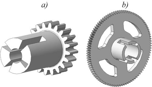
In order to investigate the mechanical resistance of the gears system, stress analysis by finite element method (FEM) was applied. As a result, material removal in low stress areas has added to the gears design. For the proposed solution, flexural modulus of PLA + of 3150 MPa was used. Additionally, fracture mechanics validation of the proposed solution was obtained with tensile stress at rupture of 45.6 MPa.[Citation28] shows the final design in CAD of both gears used as mechanical torque transmission system.
Figure 2. CAD drawing of the gears: (a) Crown and (b) Pinion.
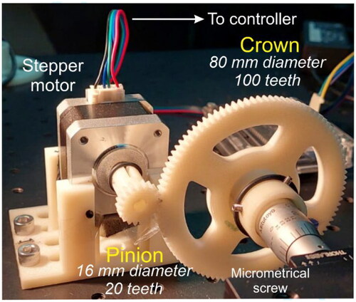
Due to the use of the proposed system as a part of an interferometer, improvements were required to avoid vibrations by reducing the effect of gravity, which compromises an adequate capture of the interferograms. For this purpose, a design modification on the crown to house the lead screw for the displacement of the optical stage was included. For the chosen PLA + material, Von Mises modulus of 34.5936 MPa for the crown and of 20.071 MPa for the pinion were chosen. Then, in comparison with the fracture stress value of 45.6 MPa, safety factors of 1.318 and 2.271 were respectively obtained. shows the assembly of the mechanical transmission system, with a base designed specifically for a Nema 17 stepper motor controlled by an Arduino interface to the computer. The electric current for the motor steps was supplied by using a dedicated digital stepper controller TB6600 allowing to prevent noise instability due to the motor energizing inhibiting the coils energizing when idle state of the motor occurs. The motor is directly adjusted to the pinion, and the crown is coupled to the micrometer screw handler.
Figure 3. Mechanical transmission system design.
Ideally, the phase shift error introduced by the transversal displacement of the grating is calculated from the backlash,[Citation25] defined as the amount by which the valley width of one gear is greater than the thickness of the engaged tooth on the other gear. For this inherent slack introduced to the angular movement in each stepper of the motor, it is possible to estimate the theoretical maximum error expected in the phase shift between two interferogram captures.[Citation29] The calculation of the lateral clearance of pinion-crown teeth in contact, according to the optimal coupling of the gear system, can be estimated from the expression:[Citation30]
(3)
(3)
where
is the normal module. According to the calculations, the clearance obtained for the proposed transmission system is of 0.0406 mm, considering the linear displacement equal to the lateral clearance between the pinion and the crown. Then, the angular displacement can be calculated by
where
is the linear displacement and
the radius of the crown. From where a maximum angular displacement introduced by the mechanical system of 8. 128 × 10−4 rad is estimated.
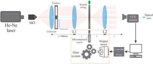
2.3. Experimental setup
In order to experimentally verify the DACPI phase shifting improvement from the gear system, the experimental setup of was implemented on a non-isolated optical table. The automatic phase shifting DACPI includes a He-Ne laser at 632.8 nm, a microscope objective and a collimator lens with 450 mm of focal length at object plane. A diffraction ruling of 500 lines per mm (
) is placed on a optical translation stage displaced by a micrometric screw (Mitutoyo Head Series 149) with a nominal resolution of 0.001 inches. The micrometric screw was coupled to the proposed gear system and rotation moved by the unipolar stepper motor. The power required to operate the motor is provided by an amplifier triggered by a microcontroller, controlled by a computer system. The 4f system is formed by L1 and L2 lenses, both with focal length of
A couple of windows was set in the object plane whose separation between their centers is
A bended acetate was placed in one of them as phase object, schematic diagram is shown in .
Figure 4. Experimental setup for automatic phase sifting DACPI.
3. Results
With the gear mechanical transmission ratio of 1/5, a single motor step of the micrometric screw generates a linear displacement of on the translation stage. Considering EquationEq. (2)
(2)
(2) with the given values of
and
the theoretical value for
is of
for each step. A set of 33 consecutive interferograms were captured and processed using a self-calibrating generalized phase-shifting interferometry (SGPSI) algorithm with a temporal spacing of
between them in non-ideal isolation conditions in terms of mechanical vibrations. The experimental phase values obtained for each shift are obtained taking three consecutive captures of the intensities of the patterns
to obtain the phase difference between the first and the second, continuing the sequence
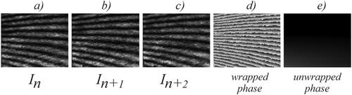
to obtain the second value, ongoing until evaluating all the patterns of the set. As an example, shows the three first captured interferograms of the set. Then, the calculated wrapped and unwrapped phase of the experimental results is also shown.
Figure 5. Experimental interference patterns: (a) (b)
(c)
(d) wrapped phase and (e) unwrapped phase.
As a result of the data process, an experimental average between steps of and a bias
were obtained. The variation coefficient with respect to the average value was of
and the obtained average standard deviation was
The obtained results represent a quantitative improvement in terms of data dispersion with respect to the previously reported in Ref.[Citation23] of
variation coefficient of
and
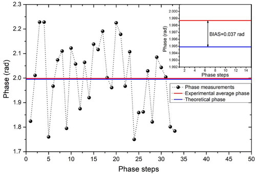
The accuracy of the proposed automatic system in terms of aggregated phase is analyzed in . The calculated phase for each phase shift of the group of interferograms are depicted (black dots). The theoretical value for the estimated aggregated phase (blue line) and the experimental calculated average phase for the set of measurements (red line) are also shown. The error range calculated as the maximum phase difference between the maximum and minimum values is of The calculated mean absolute error (MAE) from the average phase shift for the experimental results is of
As it can be observed in the inset of , the bias determined by difference between the theoretical phase and the experimental average phase is of
which represents a measurement error of 6.17%.
Figure 6. Experimental values obtained for each phase-shift, experimental and theoretical averages.
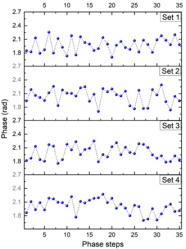
In order to investigate the repeatability of the proposed system, four sets of 35 phase shifts measurements were carried out. In , the aggregated phase for each shift are depicted for the four measurement sets. The calculated standard deviation for measurements sets 1, 2, 3, and 4 are of 0.1454, 0.1619, 0.1488, and 0.1505 rad, respectively. From the obtained results, is observed repeatable results with standard deviation around the value obtained for the results of . The maximum deviation was observed for the set 2 where the variation from the average phase value of 2.039 was of 7.9%. In addition, the MAE was calculated for each measurement sets with values of 0.1240, 0.1350, 0.1330, 0.1246, respectively for set 1, 2, 3, and 4, consistent with the MAE of 0.1233 obtained for the results of .
Figure 7. Experimental values for four measurement sets of 35 phase shifts.
4. Discussion
The experimental results of the mechanical implementation of a 1/5 gear system by means of a CAD/CAM system applied to a DACPI exhibit homogeneous phase shifts between themselves by transversal displacement of a diffraction grating. It is worth noting, even under adverse conditions of mechanical vibrations and without using a holographic optical table, the implemented system significantly improves the equally spaced phase shifting in terms of average (the difference between the theoretical and the experimental value decreased from 0.01 rad to 0.0037 rad), standard deviation (from 0.197 to 0.147), and percentage error (from 8% to 7.3%) from a previously reported approach, by using low-cost components and systems that do not require extensive calibration. It is worth to mention that the implemented system improves the possible result obtained by manual process and allows DACPI operation using a low resolution diffraction grating with which manual displacement cannot be reached due to the displacement resolution of commercial mechanical screws. For the particular case of the experimental implementation presented, it was used a 500 ln/mm grating and a micrometric screw with a resolution of 0.001 inches () which displaces 79 rad per step when manually operation is carried out, limiting the calculation of the phase by conventional methods (since most of them work in the range of
) highly increasing the error. shows a comparison between the proposed DACPI phase shifting system and some reported works based on DACPI or different interferometric systems for manual or device assisted grating displacements. As it can be observed regarding the worst case error and bias, the results obtained in this work are promising compared to other reported works. The error range exhibit significant improvement compared to similar DACPI systems with manual operation of the grating displace and it is comparable with those obtained for systems with grating displacement based on the use of piezoelectric actuators. The calculated bias obtained in the proposed system is significantly decreased for manual DACPI systems. The foregoing, taking into account that the implementation and capture conditions are not ideal, since they were carried out without a controlled environment and with an optical table not isolated from mechanical vibrations.
Table 2. Comparison in terms of worst case error and bias of reported phase-shifting systems and the proposed approach.
As a conclusion, in this work the implementation of a gear system for the optimization of phase-shift by axial translation of a diffraction grating in a DACPI is proposed and demonstrated. The calculation of the existing phase between 33 consecutive interferograms is presented using an SGPSI algorithm. The design carried out allows obtaining homogeneous phase steps with an error percentage of 7.3% and a standard deviation of 0.147 automatically which quantitatively improves what was previously reported and allows the procedure to be carried out with low-resolution grids, commercial micrometric screws, and low-cost experimental equipment, minimizing the error inherent to the human being of having been carried out manually.
Acknowledgments
Patricia Prieto-Cortés wants to thanks CONACyT Estancias Posdoctorales por México 2022.
Disclosure statement
No potential conflict of interest was reported by the author(s).
Additional information
Funding
References
- Sabella, R.; Iovanna, P.; Bottari, G.; Cavaliere, F. Optical transport for Industry 4.0 [Invited]. J. Opt. Commun. Netw. 2020, 12, 264. DOI: 10.1364/JOCN.390701.
- von Bally, G.; Schmidthaus, W.; Sakowski, H.; Mette, W. Gradient-index optical systems in holographic endoscopy. Appl. Opt. 1984, 23, 1725. DOI: 10.1364/AO.23.001725.
- Liang, H.; Peric, B.; Hughes, M.; Podoleanu, A. G.; Spring, M.; Roehrs, S. 2008 Optical coherence tomography in archaeological and conservation science - A new emerging field. 1st Canterbury Workshop on Optical Coherence Tomography and Adaptive Optics, vol. 7139. DOI: 10.1117/12.819499.
- Sharma, S.; Sheoran, G.; Shakher, C. Digital holographic interferometry for measurement of temperature in axisymmetric flames. Appl. Opt. 2012, 51, 3228. DOI: 10.1364/AO.51.003228.
- Kholkin, A. L.; Wütchrich, C.; Taylor, D. v.; Setter, N. Interferometric measurements of electric field-induced displacements in piezoelectric thin films. Rev. Sci. Instrum. 1996, 67, 1935–1941. DOI: 10.1063/1.1147000.
- Norgia, M.; Donati, S. A displacement-measuring instrument utilizing self-mixing interferometry. IEEE Trans. Instrum. Meas. 2003, 52, 1765–1770. DOI: 10.1109/TIM.2003.820451.
- Shakher, C.; Nirala, A. K. Measurement of temperature using speckle shearing interferometry. Appl. Opt. 1991, 33, 2125–2127. DOI: 10.1364/ao.33.002125.
- Mee, R.; Dontsov, D.; Langlotz, E. Interferometric device for the in-process measurement of diameter variation in the manufacture of ultraprecise spheres. Meas. Sci. Technol. 2021, 32, 074004. DOI: 10.1088/1361-6501/abe81c.
- Meneses-Fabian, C.; Rodriguez-Zurita, G.; Vazquez-Castillo, J. F.; Robledo-Sanchez, C.; Arrizón, V. Common-path phase-shifting interferometer with binary grating. Opt. Commun. 2006, 264, 13–17. DOI: 10.1016/j.optcom.2006.02.024.
- Mico, V.; Zalevsky, Z.; García, J. Superresolution optical system by common-path interferometry. Opt. Express 2006, 14, 5168. DOI: 10.1364/OE.14.005168.
- Meneses-Fabian, C.; Rodriguez-Zurita, G.; Arrizón, V. Optical tomography of transparent objects with phase-shifting interferometry and stepwise-shifted ronchi ruling. J. Opt. Soc. Am. A 2006, 23, 298. DOI: 10.1364/JOSAA.23.000298.
- Guerrero-Méndez, C.; Saucedo-Anaya, T.; Araiza-Esquivel, M.; Balderas-Navarro, R. E.; López-Martínez, A.; Olvera-Olvera, C. Measurements of concentration differences between liquid mixtures using digital holographic interferometry. Metrol. Meas. Syst. 2017, 24, 19–26. DOI: 10.1515/mms-2017-0002.
- Sokkar, T. Z. N.; El-Farahaty, K. A.; El-Bakary, M. A.; Omar, E. Z.; Hamza, A. A. Optical birefringence and molecular orientation of crazed fibres utilizing the phase shifting interferometric technique. Opt. Laser Technol. 2017, 94, 208–216. DOI: 10.1016/j.optlastec.2017.03.037.
- Meneses-Fabian, C. Self-calibrating generalized phase-shifting interferometry of three phase-steps based on geometric concept of volume enclosed by a surface. J. Opt. 2016, 18, 125703. DOI: 10.1088/2040-8978/18/12/125703.
- Jackson, D. A.; Dandridge, A.; Sheem, S. K. Measurement of small phase shifts using a single-mode optical-fiber interferometer. Opt. Lett. 1980, 5, 139. DOI: 10.1364/OL.5.000139.
- Creath, K. Phase-shifting speckle interferometry. Appl. Opt. 1985, 24, 3053. DOI: 10.1364/AO.24.003053.
- Bruno, L.; Poggialini, A.; Felice, G. Design and calibration of a piezoelectric actuator for interferometric applications. Opt. Lasers Eng. 2007, 45, 1148–1156. DOI: 10.1016/j.optlaseng.2007.06.004.
- Gomez-Conde, J. C.; Meneses-Fabian, C. Real-time measurements of phase steps out-of-range (0,2π) by a dynamic self-calibrating generalized phase-shifting algorithm. Opt. Lasers Eng. 2021, 140, 106543. DOI: 10.1016/j.optlaseng.2021.106543.
- Arrizón, V.; Sánchez-de-la-Llave, D. Common-path interferometry with one-dimensional periodic filters. Opt. Lett. 2004, 29, 141. DOI: 10.1364/OL.29.000141.
- Matsumoto, D. Radial shearing interferometer for in-process measurement of diamond turning. Opt. Eng. 2000, 39, 2696. DOI: 10.1117/1.1290463.
- Kumar, M.; Shakher, C. Measurement of temperature and temperature distribution in gaseous flames by digital speckle pattern shearing interferometry using holographic optical element. Opt. Lasers Eng. 2015, 73, 33–39. DOI: 10.1016/j.optlaseng.2015.04.002.
- Barcelata-Pinzon, A.; Meneses-Fabian, C.; Moreno-Alvarez, L.; Pastrana-Sanchez, R. Common-path speckle interferometer for phase objects studies. Opt. Commun. 2013, 304, 153–157. DOI: 10.1016/j.optcom.2013.04.066.
- Barcelata-Pinzón, A.; Álvarez-Tamayo, R. I.; Prieto-Cortés, P. A real-time automated system for dual-aperture common-path interferometer phase-shifting. Appl. Sci. 2021, 11, 7438. DOI: 10.3390/app11167438.
- Chiu, M.-H.; Lee, J.-Y.; Su, D.-C. Complex refractive-index measurement based on Fresnel’s equations and the uses of heterodyne interferometry. Appl. Opt. 1999, 38, 4047. DOI: 10.1364/AO.38.004047.
- Li, M.; Liang, R.; Zhang, Y.; Peng, C.; Mu, D.; Wan, Z. On-line measurement method of transmission backlash based on angular velocity and double-end angular position information. Meas. Control 2021, 54, 65–72. DOI: 10.1177/0020294020973252.
- Bruning, J. H.; Herriott, D. R.; Gallagher, J. E.; Rosenfeld, D. P.; White, A. D.; Brangaccio, D. J. Digital wavefront measuring interferometer for testing optical surfaces and lenses. Appl. Opt. 1974, 13, 2693. DOI: 10.1364/AO.13.002693.
- Kinnstaetter, K.; Lohmann, A. W.; Schwider, J.; Streibl, N. Accuracy of phase shifting interferometry. Appl. Opt. 1988, 27, 5082–5089. DOI: 10.1364/AO.27.005082.
- Lu, J.; Sun, C.; Yang, K.; Wang, K.; Jiang, Y.; Tusiime, R.; Yang, Y.; Fan, F.; Sun, Z.; Liu, Y.; Zhang, H.; Han, K.; Yu, M. Properties of polylactic acid reinforced by hydroxyapatite modified nanocellulose. Polymers 2019, 11, 1009. DOI: 10.3390/polym11061009.
- Geddes, D.; Noorbakhsh, J.; Yang, Z.; Preciado, M.; Normand, M.; Smith, K.; Harvey, A. R. 2022 Quantification of metabolic function in the retina using spectral imaging and phasor-FLIM. Imaging and Applied Optics Congress 2022 (3D, AOA, COSI, ISA, pcAOP), p. JW4C.3. DOI: 10.1364/COSI.2022.JW4C.3.
- AGMA913-A98, ‘Method for Specifying the Geometry of Spur and Helical Gears’, 1998.
- Gomez-Conde, J. C.; Meneses-Fabian, C. Real-time phase step measurement using the volume enclosed by a surface algorithm in self-calibrating phase-shifting interferometry. Meas. J. Int. Meas. Confed. 2020, 153, 107412. DOI: 10.1016/j.measurement.2019.107412.
- Lee, J. Y.; Jiang, G. A. Displacement measurement using a wavelength-phase-shifting grating interferometer. Opt. Express 2013, 21, 25553. DOI: 10.1364/OE.21.025553.
- Chen, X.; Gramaglia, M.; Yeazell, J. A. Phase-shifting interferometry with uncalibrated phase shifts. Appl. Opt. 2000, 39, 585. DOI: 10.1364/AO.39.000585.