
 ?Mathematical formulae have been encoded as MathML and are displayed in this HTML version using MathJax in order to improve their display. Uncheck the box to turn MathJax off. This feature requires Javascript. Click on a formula to zoom.
Abstract
During the last decade, many ophthalmic therapeutic drugs have been clinically approved, and intraocular injection has been a common surgical intervention. Injecting drugs directly into the subretinal space is crucial to treat retinal complications effectively. Here, we report a handheld microinjector with two fiber-optic distance sensors and time-delay control (TDC) to mitigate nonlinear disturbances during the injection task. The conventional method exhibited a cosine error of approximately 77 μm at an angle of 45°, whereas our proposed needle reduced measurement errors to ∼6 μm. Also, TDC-based position regulation is designed to adaptively apply motor inputs by estimating disturbances during the handheld task and achieving fast system responses with minor control errors. Phantom studies show a maximum reduction of 26.5% in root-mean-square error (RMSE) compared to the existing approach. Moreover, ex-vivo experiments demonstrated superior and robust injection performance, resulting in an injection RMSE of 10.3 μm.
1. Introduction
Several inherited retinal diseases, such as macular degeneration and retinitis pigmentosa, have an estimated 2.7 billion carriers worldwide and are expected to affect 5.5 million people, causing heterogeneous ophthalmic conditions.[Citation1] Most retinal complications stem from the subretinal dystrophies at the photoreceptor layer or retinal pigment epithelium (RPE).[Citation2] The U.S. Food and Drug Administration has recently approved several therapeutic and genetic medications showing high efficacy on various retinopathies.[Citation3] Accordingly, the estimated trials of intravitreal drug injection have continuously increased, reaching 6 million cases in 2016.[Citation4] However, the intravitreal injection allows drugs to permeate the retina by diffusion, which demands large doses and prevents targeted drug delivery.[Citation2] On the other hand, the subretinal injection can directly deliver therapeutic agents beneath the retinal membrane with high concentration and low recurrence rate of complications.[Citation5] Reproducibility and accurate injection depths are the primary requirements of subretinal injection to prevent unforeseen ocular damages, such as choroidal rupture or drug reflux, by excessive and shallow injection depths, respectively.[Citation6]
Recent advancements in the robot-assisted surgical platform have allowed surgeons to perform safe subretinal microinjection with intraoperative optical coherence tomography (OCT).[Citation7,Citation8] OCT is a classic medical imaging device that uses a broadband laser source to provide a real-time cross-section profile of the surgical site with an axial resolution of several micrometers.[Citation9,Citation10] Various biomedical sensors using OCT have been exploited, taking advantage of sharing the light source of existing OCT equipment by a fiber-optic technique. For the microinjection task, common-path OCT technology utilizing the reflected signal at the optical fiber end as a reference signal has enabled compact, non-contact, and high-resolution distance measurement between the tooltip and the surgical lesion.[Citation11–17] In addition, motorized control of the surgical tooltip facilitates a precise microsurgical injection far beyond human dexterity.
The benchtop subretinal injection instruments consisting of several motors and multi-degree-of-freedom structures have been recently used in clinical trials for in-vivo animals[Citation18] and humans.[Citation19] The robot-assisted control maintained the needle tip within from the target, compensating for
physiological retinal motions. The benchtop solutions can support a high level of autonomy; on the other hand, the handheld approaches are potentially in higher demand with a low-resource setup, intuitive operation, short training time, and fewer work steps.[Citation8] Several causes of disturbances exist in a clinical subretinal injection, such as heartbeats, breathing, and hand tremors. Among them, involuntary hand tremor is the most significant disturbance, having an amplitude and a frequency band of
and
respectively.[Citation20] To implement the handheld microinjection system as clinically applicable as the benchtop instruments did, accurate position measurements and rapid rejection of disturbances are the two critical requirements.
The previous position measurements have been done by a one-dimensional (1D) fiber-optic OCT distance sensor.[Citation12–19] It must tolerate a cosine measurement error at clinically required injection angles up to owing to an inevitable offset between the needle and the OCT sensor.[Citation21] Software-based approaches[Citation22,Citation23] and hardware-based enhancements of the sensor signal[Citation24] have been implemented to overcome inaccurate position estimation. Although the abovementioned methods can achieve reliable position estimation at 90°, a cosine error must be considered to meet the clinical demand for the oblique subretinal injection. An alternative approach, such as 2D or 3D OCT images, can be generated using a miniature beam scanner[Citation25,Citation26] or an external benchtop intraoperative OCT device, allowing for a more precise tracking of needle positions.[Citation11] Nonetheless, in the case of handheld robots, the substantial need for quick compensation of hand tremors has led to the prevalent utilization of A-line OCT signals transmitted through the fiber-optic sensor attached to the needle. As state-of-the-art control methods for handheld robotic micromanipulators, hybrid motor controllers using an optimized proportional (P), integral (I), and derivative (D) control gains with a latency-compensating motion estimator (ME) have been used to compensate for the involuntary hand tremor.[Citation13–17,Citation22,Citation27] The previous schemes could achieve a good root-mean-square-error (RMSE) of
at
however, the handheld system for clinical use has been significantly hindered by a considerable increase in RMSE at oblique angles.[Citation28]
This study demonstrates a handheld motor-assisted microinjector with two OCT sensors and a robust adaptive controller for a handheld subretinal injection application. Two high-precision OCT sensors are fabricated by fusing a single-mode fiber (SMF) and gradient-index fiber (GIF) and deployed to calculate the actual needle tip position from the sample in a 2D cross-sectional plane. In addition, the adaptive time-delay controller (TDC) is designed to compensate for the high-order nonlinear terms, including the motor hysteresis and the hand tremor, aiming to expand the control bandwidth and rapidly react to abrupt hand motions. Both phantom studies and ex-vivo experiments were performed for tremor compensation and injection results, and the proposed method could achieve a good injection performance compared to the clinically available benchtop device.
2. Materials and methods
2.1. Handheld microinjection system
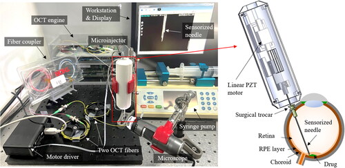
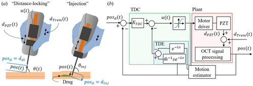
The configuration for the proposed microinjection system is shown in . A handheld microinjector comprises a sensorized needle and a linear piezoelectric (PZT) motor (LEGS-LL1011A, PiezoMotor). The needle is made by attaching two OCT distance sensors to the 33-gauge microneedle, and the outer diameter is designed to be insertable through a 25-gauge surgical trocar. The PZT motor regulates the sensorized needle tip to the desired position with high precision and speed. The microinjection system includes an OCT engine (Swept Laser OEM engine, AXSUN), 2 × 2 fiber coupler (TW1064R5A1A, Thorlabs), motor driver (PMD101, PiezoMotor), syringe pump (Fusion 100, Chemyx), and workstation (Precision T7610, Dell). One detector acquires two combined interferometric signals of both OCT sensors at a sampling rate. Subsequently, batches of one hundred samples are processed by a graphics processing unit (GPU, GeForce GTX1060, Nvidia); spectrum averaging and fast Fourier transform (FFT) are performed to acquire OCT signal by parallel GPU programming (CUDA), resulting in a system operation speed of
The motor driver operates the four piezoelectric components within the motor by controlling them through RS232 serial communication using quadratic phase modulation. In addition, the maximum motor speed of
was achieved by optimizing the motor’s resolution and speed. This speed surpasses typical hand tremor,[Citation20] making it well-suited for the control loop of the hand tremor compensation. Moreover, the syringe pump pushes the syringe with a minimum step size of
to gently inject the drug through a hydraulic tube.
Figure 1. System configuration and the schematic of the handheld microinjection system for precise subretinal injection.
2.2. High-Precision OCT sensor
For a high-precision OCT distance measurement, several lenses, such as conical,[Citation29] spherical,[Citation30] rod types,[Citation31] and the GIF[Citation32] have been employed. Among these, the GIF has various advantages such as, compactness, low cost, reduced optical losses, and simple fabrication procedures. Here, we adopted the GIF and found its optimal length and polishing angle for the high-SNR OCT signal.
The schematics of the bare SMF and GIF-attached SMF (GIF-SMF) are shown in . The radial gradient of the refractive index within the GIF bends the diverged light from the SMF, so the divergence angle, depends on the GIF’s length,
and the gradient factor of the GIF,
According to the Gaussian beam-propagation method,[Citation32] the beam divergence angle of the GIF-SMF can be approximated as follows:
(1)
(1)
(2)
(2)
(3)
(3)
where
is the refractive index of the GIF,
is a mode-field-diameter (MFD), and
is the wavelength, which are
and
respectively. To enhance the signal-to-noise ratio (SNR) along the entire measurement range,
must be minimized. Therefore, the optimal length of the GIF,
can be calculated by taking the derivative on EquationEquation (1)
(1)
(1) concerning
as follows:
(4)
(4)
where
is an integer, so
has a period dependent on
For the fabrication of the GIF-SMF, we used the commercial SMF (1060XP, Thorlabs) and the GIF (GIF625, Thorlabs) with a
of
so, the
has a period of
The bare SMF has a nominal numerical aperture (NA) and MFD of
and
respectively. The outer diameter of the GIF is the same as the SMF,
however, the GIF has a larger core diameter and NA of
and
respectively. The beam profiles captured from the SMF and the GIF-SMF along the z-axis are shown in the inset figures. We obtained several beam images from the fiber end,
to
where each image was captured using a high-resolution digital microscope (INSPEX2, Ash Technologies). The initial beam diameter of the SMF was measured as
smaller than that of the GIF-SMF,
however, the beam from the SMF rapidly diverged to
at
whereas GIF-SMF was still
at the same
It is also noticeable that the beam at
of
is mostly scattered. In contrast, the reduced divergence angle in the GIF-SMF enables the beam’s intensity to be maintained at large
values by nearly collimating the beam.
Figure 2. (a) Schematic diagrams of beam profiles exiting from the SMF and GIF-SMF along the z-axis. (b) Image of fusion splicer and fiber polisher. (c) Fiber fusing procedure. (d) Fiber polishing with a desired polishing angle, α. (e) SNR roll-of results from a mirror at 90° and an anodized aluminum plate at 45°.
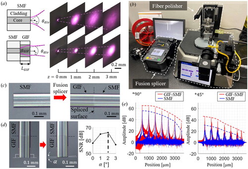
Not only is the optimal GIF length important, but the polishing angle also plays a significant role in improving the OCT signal.[Citation33] We used a fusion splicer (S178, FITEL) and fiber polisher (NOVA Polisher, KrellTech) to fabricate a high-precision OCT sensor by adjusting and the polishing angle, as shown in . The two types of optical fibers can be fused with a minimal optical loss of less than
as shown in . Then, the part of the GIF is cut and polished by the fiber polisher, as shown in . The fiber polisher can control the polishing angle,
with an accuracy of
If
equals zero, much back reflection is received from the fiber end; conversely, for a large
it is hard to obtain sufficient signals from the sample. The optimal
and polishing angle were found at
and
capable of reducing the
of the SMF and GIF-SMF from
to
respectively.
The analyses of the SNR roll-off are achieved by a mirror at various positions to compare the SNR between the SMF and the GIF-SMF, as shown in . The angle-polished GIF-SMF could provide a higher OCT amplitude than the bare SMF, resulting in a distance measurement resolution of An anodized aluminum plate is used to assess the SNR from the inclined subject as a sample and tilted at
The SMF cannot detect the signal of the tilted aluminum plate more than
from
however, the GIF-SMF can detect it through the entire measurable range with the SNR of
Hence, the proposed angle-polished GIF-SMF, in contrast to traditional lens attachment methods that solely consider beam shape, also considers the characteristics of common-path interferometric signals, facilitating an increased SNR of the OCT signals from objects at a distance or with a large inclination.
2.3. Sensorized needle
Two microscopic images of the fabricated needle are shown in and . Two OCT distance sensors are attached precisely to the opposite sides of the needle to avoid an optical cross-talk by using a home-build manufacturing zig. Each sensor has a different offset from the needle tip, which is determined to have enough measurement ranges for both position and angle using only one photodetector.
Figure 3. (a) and (b) the microscopic images of the fabricated sensorized needle. (c) Reference coordinates and system parameters of the needle.
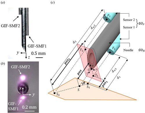
The schematic of the coordinate systems attached to the sensorized needle is shown in . Our goal is to measure the distance of the needle tip from the sample, (
), and its angle,
(
), with the measured
(
) and
(
) by the two OCT sensors.
(
) and
(
) are defined by
and
respectively.
and
are predetermined to enable
measurement from
to
and
measurement from
to
respectively.
and
can be calculated as follows:
(5)
(5)
(6)
(6)
where
and
denote the diameters of the OCT sensor and the needle, respectively. In our design,
and
are
and
respectively; so, the position error of
is obtained at
of
The average retina thickness is approximately
[Citation34] so this cosine measurement error could lead to drug reflux or cause severe retinal damage. The previous OCT-based micromanipulators have not considered
-related cosine error;[Citation12–19] thus, an unavoidable measurement error of approximately
arises from the distance between the needle tip and the sample. On the other hand, the proposed position estimation can correct this error by measuring the inclination angle, making it a more rigorous and accurate distance measurement method.
For the sensor calibration, multiple measurements at several reference positions and angles were acquired by a linear stage with resolution (Digimatic Micrometer Heads Series 350, Mitutoyo), as shown in . The calibration process was observed using a digital microscope (Dino-Lite Edge, AnMo Electronics Corporation), as depicted in the inset image. For the reference position,
we used the value obtained from the micrometer by moving the linear stage backward after bringing the needle tip into contact with the sample. In the case of the reference angle,
the microscopic image-based angle measurement was performed. The representative A-lines acquired at various angles in the calibration setup are shown in . Because only one photodetector exists, two OCT signals obtained from the two sensors are superimposed. Thus, two similar OCT signal packets exist, and we applied a dual-surface detection algorithm [Citation28] using thresholding and derivative analysis. This algorithm was designed to extract only the surface distance from the cross-sectional layer consisting of the acquired A-line. Estimating the surface layer involves relatively straightforward computation with high accuracy, rendering it compatible with the high-speed time delay estimation controller.
Figure 4. (a) The schematic diagram of the calibration setup. (b) Representative A-lines obtained by the implemented sensorized needle. (c) The calibrated angle measurement results from 40 ° and 140 °. (d) Comparison of the position measurement results at 45 °.
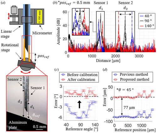
The calibration is performed to determine the optimal system parameters that can provide the least RMSE for both and
The angle measurement accuracy is analyzed from
to
with the angular step size of
as shown in . The square dots are the mean of the measurement errors at each reference angle, and the error bars represent the standard deviations; the calibrated results have the maximum mean and the standard deviation of
and
respectively. The comparison between the two position measurements at
is shown in . The previous position measurement cannot accurately measure the needle tip position with a cosine measurement error of
In contrast, the proposed position estimation could obtain fewer errors of
up to the reference position of
The measurable range at
is limited to
owing to the increased signal gap distance within the OCT’s measurable range of
Thus, while traditional 1D position information is susceptible to cosine measurement errors, adding an extra fiber-optic sensor maintains sensor precision and high measurement accuracy. Moreover, it does not significantly increase system complexity, as two distance measurements can be obtained using a single detector.
2.4. Design and implementation of the time-delay-controller
Various control methods such as iterative gain scheduling,[Citation35] sliding-mode control,[Citation36] a hysteresis model-predictive controller,[Citation37] and the TDC [Citation38] have been adopted to cope with the disturbances and inherent nonlinearities of the actuator. The TDC is an adaptive motor controller with a fast operation speed and is suitable for a handheld instrument with uncertain dynamics and considerable disturbances.
The presented system has two operation modes, as shown in : distance locking and injection. In the distance-locking, the desired value,
, is denoted as
here, we set
to
is the injection depth to which the motor must push the needle to reach the target layer. The value of
is determined by the OCT microscopy before injection, and
is the measured injection angle.
Figure 5. The schematic of the proposed control algorithm. (a) Two operation modes of the handheld microinjector: distance-locking and injection. (b) The block diagram of the position regulation feedback loop using the proposed time delay controller.
Once the control is started, the motor input is applied to regulate
and
is the displacement of the PZT rod; here,
controls the velocity of the PZT rod
, as follows:
(7)
(7)
where
is the scaling factor from the motor input to the output velocity, and
is an unpredictable nonlinear term. Due to the hysteresis of the PZT, the different scaling factors are measured along each direction as
for the positive direction and
for the negative direction, respectively. In addition, the
reaches its saturation value at the motor input of
As an estimated scaling factor,
we used the mean value between
and
A first-order dynamic equation is built by using the time-derivatives of
and
as follows:
(8)
(8)
Here, both velocities of the PZT motor and hand tremor give unpredictable disturbances to the system. We define as a combined nonlinear term including both the PZT motor and hand tremor;
Therefore, EquationEquation (8)
(8)
(8) can be expressed by estimated values as follows:
(9)
(9)
where
is the estimated value of
which equals to
Employing the time-delay estimation (TDE), can be approximated to
where
refers to the least time interval. The presented system is operated at
however, the system delay, including computational and transport latencies, is measured as
so
is regarded as
It is still fast enough to apply the TDE to physiological hand tremors, ranging from
to
[Citation20]
can thus be calculated by
which are known values. The motor input in EquationEquation (9)
(9)
(9) can be expressed as follows:
(10)
(10)
The error, is defined as
and
is a constant. Here, the desired error dynamics of
with a proportional control gain of
can be applied, which returns the motor input for the TDC as follows:
(11)
(11)
Therefore, uses one control gain
(
), and a nonlinear term can be calculated by the previously measured positions and motor inputs.
The block diagram of the proposed system is shown in . We developed custom operation software based on Visual C++ and the Microsoft Foundation Class (MFC) library. This software comprises two synchronized threads: one for acquiring the OCT spectrum and the other for the OCT signal processing with the CUDA programming, and
calculation and applying the motor input. At the OCT signal processing block, two distance indexes from the processed OCT signal are first acquired by the surface detection algorithm using a low-pass filter, thresholding, and derivatives.[Citation28] Subsequently,
and
are calculated and stored in a buffer with a size of
A temporal moving average filter is applied to the position buffer to reduce high-frequency noise. As a motion estimator (ME), the derivative of the filtered position buffer is used to obtain the delay compensation term.[Citation39] This estimator using the delayed motion buffer is remarkably efficient and robust when
is small enough and has been adopted to estimate physiological motion for robot-assisted surgery.
The proportional gain is multiplied by the error to calculate the motor input. In addition, the TDE-based nonlinear term is calculated by considering the previous position and motor input, as indicated by the blue dotted box. The TDE result is combined with
and the saturation function of
is applied to apply motor input limits. The motor driver moves the PZT motor with a velocity of
and nonlinear disturbances are added from both
and
The step response of the microinjector is studied to optimize the control gain using three control methods: P controller with motion estimation (ME) (P + ME),[Citation28] PID controller with ME (PID + ME),[Citation13–17,Citation22,Citation27] and the proposed TDC. Ziegler and Nichols’s gain tuning method [Citation40] is adopted to determine each control gain heuristically, as shown in , and a step signal from to
is used to compare three control methods in terms of the transient responses, such as rising and settling times and overshoot, as shown in . For the P + ME controller, the optimal proportional gain,
is selected to
It shows a rising time of
an overshoot of
and a settling time of
for the
criterion. The PID + ME controller is implemented by introducing the integration gain (
and derivative gains (
).
and
enhanced the system response; however, excessive overshoot and oscillation occur when considerable disturbances are applied. Therefore, the optimal combinations of PID gains are obtained at a slightly lower
of
with
and
of
and
respectively. The PID + ME can achieve a faster settling time of
with less overshoot of
than the results of the P + ME controller. The proposed TDC has one control gain,
and it is noticeable that the proposed TDC has a minor overshoot and damped oscillations, as indicated by the asterisks. The optimized
is
with the fastest settling time of
and the smallest overshoot of
Figure 6. The control gain optimization of (a) P, (b) PID, and (c) TDC. (d) The comparison of the step responses and (e) the motor inputs by the conventional methods and the proposed TDC method with the optimized control gain.
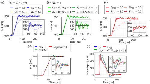
The recorded motor inputs for each control method during the step response are shown in . As the asterisks indicate, the proposed TDC can react faster than other methods to get fewer overshoots and settling times for the same rising time. Subtraction of the TDE nonlinear term, allows applying the higher motor input with less damped oscillations, resulting in a faster response. The proposed TDC can effectively regulate the needle tip position by rapidly rejecting the disturbance with less overshoot.
3. Results and discussions
3.1. Control results on recorded hand tremors
We designed the experiment using the recorded tremor to validate control performances, as shown in . The hand tremors are recorded for seconds without applying the motor input, as shown in the inset. Subsequently, a position regulation task was performed where the system tracked a target position derived from the recorded hand tremor. An aluminum plate is mounted on a rotational stage to analyze the effect of the tilted angle on the control performance. Even though the same recorded tremor is applied, the control performances of each method are affected by the tilted angle. Ten recorded
are used as the desired position, and the tracking performance is evaluated at different reference angles from
to
by fixing the microinjector.
Figure 7. (a) Schematic diagram of the experiment on the recorded tremor. (b) Representative tracking results on the simulated hand tremor at 45°.
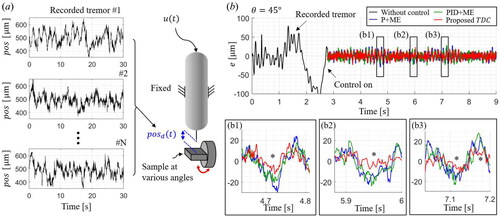
The part of the representative control results at of
is shown in . The black line indicates the error when the motor input is not used. Then, each control method is applied to compensate for the same recorded tremor. The proposed TDC shows the fastest reaction to the sudden changes in disturbance than the other methods, as indicated by the asterisks in three inset graphs. The abrupt error changes stem from both the hand’s sudden movements and the motor’s non-uniform stroke. Hence, the proposed TDC enhances the system response to these instantaneous disturbances while preventing an extensive motor input.
The RMSE results of three control methods at each reference angle are shown in . Ten recorded tremors are applied at each reference angle from to
with
intervals. For all the control methods, the least RMSE is achieved when
is
and the control performance gets worse as
deviates from
The one-tailed t-test is conducted with the hypothesis that one RMSE dataset is statistically lower than the other. The
-value is the probability of rejecting the above hypothesis, so the lower
the more apparent the difference between the two datasets. One asterisk (
) and two asterisks (
) indicate
of less than
and
respectively. The proposed TDC is shown to have the lowest RMSE values for all angles with a confidence level of
the minimum and maximum mean RMSEs are
and
at
and
respectively. The corresponding values for the P + ME and PID + ME are
and
as well as
and
respectively.
Figure 8. (a) RMSE control results of each control method at several angles. (b) Comparison of position regulation results by each control method.
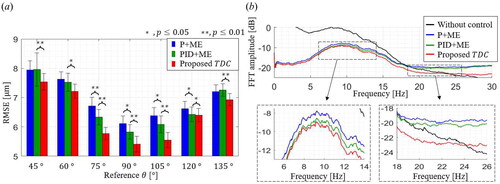
The frequency-domain analysis is also performed, as shown in . The black line represents the FFT result of all recorded tremors (total time length is 35 minutes) without position regulation. There is an upwards convex trend in the 5 Hz to 20 Hz range, which agrees with the well-known bandwidth of involuntary hand tremors.[Citation20] It is also noticeable that the shape of FFT results is almost the same, which indicates that all the control results have similar residual errors on the same disturbances.
All the control methods significantly reduced the FFT amplitude in the decibel scale, and the TDC shows the least FFT amplitudes among all the frequency ranges. The inset graphs show the FFT amplitudes in the frequency ranges of to
and
to
respectively. The FFT result of the proposed TDC gets lower than the other two control methods as the analysis frequency band increases. The results of the P + ME and the PID + ME become higher FFT values than the recorded tremor at
which means the two control methods have high-frequency residual errors. On the other hand, the proposed TDC could show the reduction of the hand tremor over a wider frequency band up to
The TDC can efficiently drive the motor to compensate for high-frequency disturbance.
3.2. Injection results on an agarose-gel phantom study
An injection phantom made of agarose gel is prepared to have an average eyeball curvature, as shown in . As an experimental protocol, the needle is moved from the right to left sides of the agar phantom and is inserted at three injection points where the tilted angles are
and
The target injection depth is determined to be
beneath the sample surface, so the desired
values for each injection are
and
respectively. Distance locking is operated when we transversely move the needle location from the first to the last injection place. Thus, the needle tip position is maintained from the sample surface, and the measured angle continuously changes from
to
Figure 9. Injection performances on the eyeball phantom made of 2 % agarose-gel. (a) Schematic of the injection experiment with three injection points at tilted angles of 45 °, 90 °, and 135 °. (b) The representative θ and pos measurement results during the one-cycle injection experiment. (c) The representative microscopic images, OCT images, and pos measurements during the injection at each desired point. (d) Comparison of RMSE results during the injection for each control method.
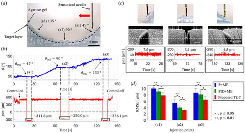
The representative and
measurement results with the proposed TDC are shown in . Three injections were made at the
of
and
and the averages of
for each injection were
and
respectively. The more inclination increases, the more considerable injection depth is required to get the same needle tip position from the sample surface. The microscopic and OCT images at each injected point are shown in . The commercial OCT microscope (Callisto
OCT Imaging System, Thorlabs) is used to visualize the cross-section of the injected agar phantom, and the white dotted line indicates the target depth. The needle has been inserted to the consistent depths for all angles, and RMSE values are measured to
and
respectively. Furthermore, we compared the injection experiment results for each control method: P + ME, PID + ME, and TDC, as shown in . The RMSE results of the TDC are statistically lower than the other two methods, with
confidence level. The TDC’s best and worst averaged RMSE results are
and
respectively, resulting in average improvements of
and
from the P + ME and the PID + ME, respectively.
3.3. Injection results on ex-vivo porcine eye
A porcine eye is used as an ex-vivo sample to perform the subretinal injection, as shown in . The porcine eye was achieved from the slaughterhouse on the day of slaughter. We observed the injection procedure through a microscope, and two illuminations from OCT sensors can be visualized, as shown in the inset image. The target layer is an RPE, and indocyanine green (ICG) is used as an injection material. The representative results of the measured and
are shown in . Two control types can be clearly distinguished: distance-locking and injection and the injection has been performed at the measured injection angle of
The calculated injection depth is
and the control RMSE is measured as
The needle was maintained under the retina for over
seconds while gently perfusing ICG.
Figure 10. Injection results on an ex-vivo porcine eye. (a) Experimental setup image of the porcine eye injection and the microscopic image of the sensorized needle. (b) Representative θ and pos measurement results during the ex-vivo porcine eye experiment. (c) 3D OCT images of the injected ex-vivo porcine eye (c1) with cosine measurement error and (c2) without cosine measurement error. (d) 2D OCT images: (d1) en-face image of the injected layer and cross-section images of both (d2) non-injected and (d3) injected area.
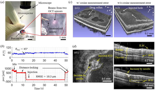
The typical injection results are shown in . The desired injection angle is set to so the cosine measurement error accounts for
This error made shallow injection depth, often causing drug reflux, as shown in . On the contrary, the proposed sensorized needle can compensate for the cosine measurement error, providing the accurate position estimation of the needle tip at an oblique angle. It results in a successful injection, as shown in . Both an injected hole and a subretinal bleb could be observed.
2D en-face and cross-sectional images of the injected lesion are acquired, as shown in . The acquired en-face image can visualize the punched hole by the needle and injected ICG, as shown in inset . In the case of the non-injected area, an intact ILM, retina, choroid, and RPE layer can be observed, as shown in . On the other hand, the injected area has an incision by the needle and the injected ICG, as shown in . Hence, the ICG has been successfully injected at the RPE layer between the retina and choroid.
4. Conclusion
In this study, a sensorized handheld microinjector with an adaptive TDC was proposed and implemented to achieve precise robot-assisted subretinal injection. Two OCT distance sensors measure the position and angle between the needle tip and the target sample. The presented estimation could mitigate inevitable cosine measurement errors. In addition, a TDC scheme was designed to compensate for disturbances effectively with the improved control RMSE, broaden control bandwidth, and rapidly respond to the abrupt involuntary motions. We demonstrated that the proposed system performed better than the conventional methods through the recorded tremor and the phantom injection experiments. Our proposed TDC method excels in its adaptive estimation of system nonlinearity and disturbances, which empowers it to provide rapid and robust control over a broad spectrum of hand tremor patterns. This effectiveness is consistently demonstrated through significant performance improvements in both the time and frequency domains. We examined the ex-vivo porcine eye to perform an actual injection of a drug to the RPE layer. The proposed method was able to accurately estimate the inclined needle tip position at the clinically demanded injection angle, so it can significantly alleviate both drug reflux and retinal damage. Moreover, the needle position can be precisely maintained at the desired depth with an RMSE of
comparable to the recent benchtop robotic in-human study.
The proposed method is anticipated to serve as a crucial step toward a handheld microinjection system, facilitating precise motor regulation and accurate position estimation for clinical use. Here, we utilized two fiber-optic sensors to ensure compatibility with commercial intraoperative OCT, which provides real-time retinal cross-sectional imaging. However, as part of our future work, we are actively working on incorporating another distance sensor for 3D position estimation. To develop a more versatile sensorized needle, exploring optimal hardware and software design is crucial. It includes ensuring a needle with a small enough diameter to be compatible with standard surgical trocars, while enabling fast and precise position regulation control. Further studies are also required to integrate with a clinical subretinal injection procedure. In addition, these sensorized needles and TDC-based position regulations can be applied to other industrial or medical applications where accurate position estimation and disturbance rejection play essential roles.
Disclosure statement
No potential conflicts of interest was reported by the author(s).
Additional information
Funding
References
- Hanany, M.; Rivolta, C.; Sharon, D. Worldwide carrier frequency and genetic prevalence of autosomal recessive inherited retinal diseases. Proc. Natl. Acad. Sci. USA 2020, 117, 2710–2716. DOI: 10.1073/pnas.1913179117.
- Irigoyen, C.; Amenabar Alonso, A.; Sanchez-Molina, J.; Rodríguez-Hidalgo, M.; Lara-López, A.; Ruiz-Ederra, J. Subretinal injection techniques for retinal disease: A review. J. Clin. Med. 2022, 11, 4717. DOI: 10.3390/jcm11164717.
- Parikh, R.; Ross, J. S.; Sangaralingham, L. R.; Adelman, R. A.; Shah, N. D.; Barkmeier, A. J. Trends of anti-vascular endothelial growth factor use in ophthalmology among privately insured and medicare advantage patients. Ophthalmology 2017, 124, 352–358. DOI: 10.1016/j.ophtha.2016.10.036.
- Ramos, M. S.; Xu, L. T.; Singuri, S.; Castillo Tafur, J. C.; Arepalli, S.; Ehlers, J. P.; Kaiser, P. K.; Singh, R. P.; Rachitskaya, A. V.; Srivastava, S. K.; et al. Patient-reported complications after intravitreal injection and their predictive factors. Ophthalmol. Retina 2021, 5, 625–632. DOI: 10.1016/j.oret.2020.09.024.
- Yao, T.-T.; Jin, X.-L.; Yang, Y.; Wang, Y.-X.; Zhou, Y.-L.; He, F.-L.; Wang, Z.-Y. Intraocular pharmacokinetics and safety of subretinal injection compared with intravitreal application of conbercept in vitrectomized rabbit eyes. J. Ophthalmol. 2020, 2020, 2674780. DOI: 10.1155/2020/2674780.
- Xue, K.; Groppe, M.; Salvetti, A. P.; MacLaren, R. E. Technique of retinal gene therapy: Delivery of viral vector into the subretinal space. Eye 2017, 31, 1308–1316. DOI: 10.1038/eye.2017.158.
- Ladha, R.; Caspers, L. E.; Willermain, F.; de Smet, M. D. Subretinal therapy: Technological solutions to surgical and immunological challenges. Front. Med. (Lausanne) 2022, 9, 846782. DOI: 10.3389/fmed.2022.846782.
- Iordachita, I. I.; De Smet, M. D.; Naus, G.; Mitsuishi, M.; Riviere, C. N. Robotic assistance for intraocular microsurgery: Challenges and perspectives. Proc. IEEE. Inst. Electr. Electron. Eng. 2022, 110, 893–908. DOI: 10.1109/JPROC.2022.3169466.
- Chen, Y.; Aguirre, A. D.; Hsiung, P. L.; Huang, S. W.; Mashimo, H.; Schmitt, J. M.; Fujimoto, J. G. Effects of axial resolution improvement on optical coherence tomography (OCT) imaging of gastrointestinal tissues. Opt. Express. 2008, 16, 2469–2485. DOI: 10.1364/OE.16.002469.
- Wang, D.; Zhang, J.; Liu, L.; Yan, Z.; Wang, P.; Ding, Y.; Xie, H. Application of OCT for osteonecrosis using an endoscopic probe based on an electrothermal MEMS scanning mirror. Int. J. Optomechatronics 2021, 15, 87–96. DOI: 10.1080/15599612.2021.1923876.
- Zhou, M.; Yu, Q.; Huang, K.; Mahov, S.; Eslami, A.; Maier, M.; Lohmann, C. P.; Navab, N.; Zapp, D.; Knoll, A.; et al. Towards robotic-assisted subretinal injection: A hybrid parallel–serial robot system design and preliminary evaluation. IEEE Trans. Ind. Electron. 2020, 67, 6617–6628. DOI: 10.1109/TIE.2019.2937041.
- Cereda, M. G.; Parrulli, S.; Douven, Y. G. M.; Faridpooya, K.; van Romunde, S.; Hüttmann, G.; Eixmann, T.; Schulz-Hildebrandt, H.; Kronreif, G.; Beelen, M.; et al. Clinical evaluation of an instrument-integrated OCT-based distance sensor for robotic vitreoretinal surgery. Ophthalmol. Sci. 2021, 1, 100085. DOI: 10.1016/j.xops.2021.100085.
- Song, C.; Gehlbach, P. L.; Kang, J. U. Active tremor cancellation by a “smart” handheld vitreoretinal microsurgical tool using swept source optical coherence tomography. Opt. Express. 2012, 20, 23414–23421. DOI: 10.1364/OE.20.023414.
- Huang, Y.; Liu, X.; Song, C.; Kang, J. U. Motion-compensated hand-held common-path fourier-domain optical coherence tomography probe for image-guided intervention. Biomed. Opt. Express. 2012, 3, 3105–3118. DOI: 10.1364/BOE.3.003105.
- Song, C.; Park, D. Y.; Gehlbach, P. L.; Park, S. J.; Kang, J. U. Fiber-optic OCT sensor guided “SMART” micro-forceps for microsurgery. Biomed. Opt. Express. 2013, 4, 1045–1050. DOI: 10.1364/BOE.4.001045.
- Yeo, C.; Park, H. C.; Jang, S.; Gehlbach, P. L.; Song, C. Dual optical coherence tomography sensor guided, two-motor, horizontal SMART micro-scissors. Opt. Lett. 2016, 41, 4723–4726. DOI: 10.1364/OL.41.004723.
- Koo, D.; Park, H. C.; Gehlbach, P. L.; Song, C. Development and preliminary results of bimanual smart micro-surgical system using a ball-lens coupled OCT distance sensor. Biomed. Opt. Express. 2016, 7, 4816–4826. DOI: 10.1364/BOE.7.004816.
- Ourak, M.; Smits, J.; Esteveny, L.; Borghesan, G.; Gijbels, A.; Schoevaerdts, L.; Douven, Y.; Scholtes, J.; Lankenau, E.; Eixmann, T.; et al. Combined oct distance and fbg force sensing cannulation needle for retinal vein cannulation: In vivo animal validation. Int. J. Comput. Assist. Radiol. Surg. 2019, 14, 301–309. DOI: 10.1007/s11548-018-1829-0.
- Cehajic-Kapetanovic, J.; Xue, K.; Edwards, T. L.; Meenink, T. C.; Beelen, M. J.; Naus, G. J.; de Smet, M. D.; MacLaren, R. E. First-in-human robot-assisted subretinal drug delivery under local anesthesia. Am. J. Ophthalmol. 2022, 237, 104–113. DOI: 10.1016/j.ajo.2021.11.011.
- Riviere, C. N.; Gangloff, J.; De Mathelin, M. Robotic compensation of biological motion to enhance surgical accuracy. Proc. IEEE 2006, 94, 1705–1716. DOI: 10.1109/JPROC.2006.880722.
- He, C. Y.; Huang, L.; Yang, Y.; Liang, Q. F.; Li, Y. K. Research and realization of a master-slave robotic system for retinal vascular bypass surgery. Chin. J. Mech. Eng. 2018, 31, 10. DOI: 10.1186/s10033-018-0278-6.
- Cheon, G. W.; Gonenc, B.; Taylor, R. H.; Gehlbach, P. L.; Kang, J. U. Motorized micro-forceps with active motion guidance based on common-path SSOCT for epiretinal membranectomy. IEEE ASME Trans. Mechatron. 2017, 22, 2440–2448. DOI: 10.1109/TMECH.2017.2749384.
- Lee, S.; Kang, J. U. CNN-based CP-OCT sensor integrated with a subretinal injector for retinal boundary tracking and injection guidance. J. Biomed. Opt. 2021, 26, 068001. DOI: 10.1117/1.JBO.26.6.068001.
- Abid, A.; Duval, R.; Boutopoulos, C. Development and ex-vivo validation of 36G polyimide cannulas integrating a guiding miniaturized OCT probe for robotic assisted subretinal injections. Biomed. Opt. Express. 2022, 13, 850–861. DOI: 10.1364/BOE.448471.
- Im, J.; Chang, Y.; Song, C. Modified phase-offset-driven lissajous scanning endomicroscopy with a polyimide-film-based frequency separator. IEEE/ASME Trans. Mechatron. 2022, 27, 4829–4839. DOI: 10.1109/TMECH.2022.3166453.
- Im, J.; Chang, Y.; Lee, M. H.; Do, D.; Lee, K.; Gweon, D.; Song, C. Lissajous confocal fluorescent endomicroscopy with a lever mechanism and a frequency separation by an asymmetric polymer tube. Int. J. Optomechatronics 2023, 17, 2238009. DOI: 10.1080/15599612.2023.2238009.
- MacLachlan, R. A.; Becker, B. C.; Tabarés, J. C.; Podnar, G. W.; Lobes, L. A.; Riviere, C. N. Micron: An actively stabilized handheld tool for microsurgery. IEEE Trans. Robot. 2011, 28, 195–212. DOI: 10.1109/TRO.2011.2169634.
- Im, J.; Song, C. Oblique injection depth correction by a two parallel OCT sensor guided handheld SMART injector. Biomed. Opt. Express. 2021, 12, 926–939. DOI: 10.1364/BOE.410492.
- Kim, J. H.; Han, J. H.; Jeong, J. Common-path optical coherence tomography using a conical-frustum-tip fiber probe. IEEE J. Sel. Top. Quantum Electron 2013, 20, 8–14. DOI: 10.1109/JSTQE.2013.2277817.
- Zhao, M.; Huang, Y.; Kang, J. U. Sapphire ball lens-based fiber probe for common-path optical coherence tomography and its applications in corneal and retinal imaging. Opt. Lett. 2012, 37, 4835–4837. DOI: 10.1364/OL.37.004835.
- Gill, K. K.; Riesen, N.; Priest, C.; Phillips, N.; Guan, B.; Lancaster, D. G. On-chip absorption spectroscopy enabled by graded index fiber tips. Biomed. Opt. Express. 2021, 12, 181–190. DOI: 10.1364/BOE.414239.
- Zhang, Y.; et al. Fringe visibility enhanced extrinsic Fabry–Perot interferometer using a graded index fiber collimator. IEEE Photon. J 2010, 2, 469–481. DOI: 10.1109/JPHOT.2010.2049833.
- Fu, X.; Patel, D.; Zhu, H.; MacLennan, G.; Wang, Y. T.; Jenkins, M. W.; Rollins, A. M. Miniature forward-viewing common-path OCT probe for imaging the renal pelvis. Biomed. Opt. Express. 2015, 6, 1164–1171. DOI: 10.1364/BOE.6.001164.
- Bagci, A. M.; Shahidi, M.; Ansari, R.; Blair, M.; Blair, N. P.; Zelkha, R. Thickness profiles of retinal layers by optical coherence tomography image segmentation. Am. J. Ophthalmol. 2008, 146, 679–687. DOI: 10.1016/j.ajo.2008.06.010.
- Huang, D.; Xu, J. X.; Venkataramanan, V.; Huynh, T. C. T. High-performance tracking of piezoelectric positioning stage using current-cycle iterative learning control with gain scheduling. IEEE Trans. Ind. Electron. 2014, 61, 1085–1098. DOI: 10.1109/TIE.2013.2253071.
- Feng, Z.; Liang, W.; Ling, J.; Xiao, X.; Tan, K. K.; Lee, T. H. Precision force tracking control of a surgical device interacting with a deformable membrane. IEEE/ASME Trans. Mechatron. 2022, 27, 5327–5338. DOI: 10.1109/TMECH.2022.3177792.
- Hu, Z.; Maul, G. P. Vibration control of piezoelectric actuator by implementation of optical positioning sensor. Int. J. Optomechatronics 2007, 1, 369–382. DOI: 10.1080/15599610701672561.
- Baek, S.; Baek, J.; Kwon, W.; Han, S. An adaptive model uncertainty estimator using delayed state-based model-free control and its application to robot manipulators. IEEE/ASME Trans. Mechatron. 2022, 27, 4573–4584. Dec. 2022. DOI: 10.1109/TMECH.2022.3160495.
- Bowthorpe, M.; Tavakoli, M. Physiological organ motion prediction and compensation based on multirate, delayed, and unregistered measurements in robot-assisted surgery and therapy. IEEE/ASME Trans. Mechatron. 2016, 21, 900–911. DOI: 10.1109/TMECH.2015.2482391.
- Wang, F.; Shi, B.; Huo, Z.; Tian, Y.; Zhang, D. Design and control of a spatial micromanipulator inspired by deployable structure. IEEE Trans. Ind. Electron. 2022, 69, 971–979. DOI: 10.1109/TIE.2021.3053899.