
 ?Mathematical formulae have been encoded as MathML and are displayed in this HTML version using MathJax in order to improve their display. Uncheck the box to turn MathJax off. This feature requires Javascript. Click on a formula to zoom.
Abstract
Microparticle sorting is a crucial technique with diverse applications spanning biomedical research, microfluidics, and beyond. Conventional methods often face limitations in throughput, precision, and sample integrity. Here we present an optofluidic approach for size-based directional sorting of microparticles using optical manipulation with Airy beams. By harnessing the non-diffracting properties and transverse gradient force of Airy beams, we achieve a non-invasive, high-precision sorting method capable of sorting and selectively clearing microparticles based on their sizes. We also demonstrate more complex operations involving wavefront modulation and microfluidic devices. The proposed method offers effective and versatile microparticle sorting, providing a powerful optofluidic tool for applications requiring precise and efficient sorting of microparticles while maintaining sample integrity.
1. Introduction
Sorting of microparticle often necessities a fundamental process in various scientific research and industrial applications, ranging from biomedical research and drug delivery to materials science and environmental monitoring,[Citation1–3] where the ability to efficiently separate and isolate microparticles based on their size often serves as cruciality for achieving desired functionalities and performance in these fields. Methods such as filtration,[Citation4,Citation5] centrifugation,[Citation6,Citation7] and electrophoresis,[Citation8,Citation9] have been widely adopted for particle sorting, but often face limitations in terms of throughput, precision, and potential damage to the particles. Further limiting their applicability in biological and chemical applications, these techniques may not be suitable for sorting particles in microfluidics, which can serve as essential tools in lab-on-a-chip technologies and point-of-care diagnostics. Optical manipulation techniques stand out in this regard to offer non-invasive, high-precision, and label-free particle manipulation, thus reaching high compatibility with miniaturized microfluidic platforms.[Citation10–15] These methods utilize the interaction between light and matter to exert forces on particles, enabling their manipulation and control. Optical manipulation techniques can realize sorting particles or cells based on their physical properties, which is especially valuable in biomedical and chemical analysis. Previous studies have demonstrated optical sorting methods, such as by manipulating the optical force of a laser beam,[Citation16] optically induced dielectrophoretic,[Citation17] laser tweezers Raman spectroscopy,[Citation18] and optical chromatography techniques. Despite the high efficiency and precision of spectroscopic sorting techniques for particle separation, limitations such as high cost, throughput constraints, sample preparation requirements, and data analysis complexity remain. Noteworthily, the use of structured light and special beam modes has gained significant attention due to their unique properties,[Citation14] and especially with the unparalleled versatility from the holographic wavefront manipulation.[Citation19,Citation20] In particular, Airy beams, a class of non-diffracting optical beams, have shown great potential for microparticle manipulation.[Citation21–24] Airy beams possess several remarkable and unique properties, including self-acceleration, self-healing, and resistance to diffraction.[Citation21,Citation25,Citation26] These characteristics make them well-suited for trapping and manipulating microparticles in a controllable manner.[Citation27,Citation28] The asymmetric intensity profile of Airy beams gives rise to a transverse gradient force that can be exploited for particle sorting based on size. By carefully designing the beam parameters and the optical system, it is possible to achieve selective manipulation of microparticles with different diameters.
In this paper, we propose a novel method for size-based optofluidic microparticle sorting using Airy beam optical manipulation. Our approach leverages the distinct optical forces exerted by Airy beams on microparticles with different sizes to selectively distribute them at different depths and/or areas within a liquid surface. By controlling the intensity and trajectory of the Airy beams, and particle size distribution, we demonstrate the ability to efficiently separate microparticles based on their size using a custom-built optical manipulation setup. The setup consists of microfluidic channels containing a suspension of microparticles with different diameters, illuminated by an Airy beam generated using a spatial light modulator (SLM). By carefully adjusting the beam parameters and the liquid properties, we achieve precise control over the sorting process. The experimental results are analyzed and compared with theoretical predictions to validate the underlying physical principles and optimize the sorting performance. The proposed method allows for sorting with high precision, non-invasiveness, and compatibility with liquid environments, overcoming the limitations of traditional sorting techniques and leading to discovery of novel micro-manipulation applications.
2. Results
2.1. Sorting mechanisms and experiment design
In the Mie-scattering regime, the optical force exerted on a microparticle can be decomposed into two components: the scattering force (FS) and the gradient force (FG). FS is parallel to the beam propagation direction, while FG is perpendicular to it. For microparticles illuminated by the light beam, different modes of motion can be achieved by combining FS and FG in various ratios. With the commonly used Gaussian beams, stable particle trapping is achieved through balancing FS and FG. In contrast, the Airy beam is a unique optical field with self-acceleration and non-diffracting properties, theoretically discovered when solving the Schrödinger equation and described by an Airy function.[Citation29] In practice, an Airy beam can be generated by modulating a Gaussian beam with a cubic phase[Citation22] using, for example, a spatial light modulator (SLM) (see Methods for details). Two key parameters, the direction angle (θ) and the inner radius (r˜), govern the precise control of the beam’s propagation direction and non-diffracting propagation distance, enabling meticulous adjustment of particle motion trajectories and the forces acting on them. As shown in , while θ directly controls the angle of the intensity distribution in the x-y plane, the non-diffracting propagation diminishes with an increasing r˜, causing the beam to degrade into a Gaussian beam more rapidly. These parameters allow for precise manipulation of the forces acting on particles and their motion trajectories within the optical field, making the Airy beam an ideal tool for optical sorting.
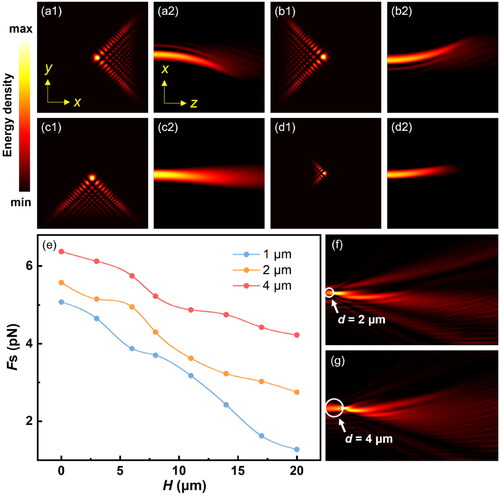
Figure 1. Sorting mechanisms. (a-d) Optical field distributions of 2-dimensional (2D) Airy beams in x-y and x-z planes with different inner radii () and direction angles (θ). (a)
= 0.2, θ = −0.25π; (b)
= 0.2, θ = 0.25π; (c)
= 0.2, θ = 0.75π; (d)
= 0.5, θ = 0.25π. (e) Calculated FS exerted on PS particles as functions of H. (f, g) Calculated intensity distributions of the Airy beam after refraction from PS particles (marked by white rings) with diameters of (f) 2 μm and (g) 4 μm.
To study the feasibility of sorting by examining how optical forces (FO) change with different values of inner radius and particle sizes, numerical simulations were conducted using a finite element method (COMSOL Multiphysics 6.1, see Methods for details). To reduce computational complexity, the simulations were performed for one-dimensional (1D) Airy beams, providing a qualitative understanding of how particle size and inner radius affect the magnitude of the FO, in particular the FS. The FO exerted on a particle with a surface area S can be expressed as:
(1)
(1)
where n is the surface normal vector, and ⟨TM⟩ is the time-independent Maxwell stress tensor, given by:
(2)
(2)
where EE* and HH* denote the outer product of the optical fields, Q is the unit dyadic, and ε and μ are the electric permittivity and magnetic permeability of the surroundings, respectively. shows the FS exerted on polystyrene (PS) particles as functions of the height H from the focal point in the same Airy beam with r˜ = 0.2 for particles of different diameters, resulting from the different refraction patterns and thus distinct momentum transfer shown in . The results indicate that, regardless of the displacement, the FS acting on the particles increases with particle size, suggesting that an Airy beam can propel larger particles to higher positions, allowing for size-based particle sorting by sending particles of different sizes to different heights above the initial surface.
The experimental realization of microparticle sorting using Airy beams was conducted on a holographic optical tweezer (HOT) system, as schematically shown in . A continuous-wave 1064 nm solid-state laser (Maxphotonics, MFSC-30W-CEA1.0) provides the initial Gaussian beam with an M2 value less than 1.2. The laser beam is then polarized by a linear polarizer (P) (Thorlabs, GL10-C26) and expanded by a telescope consisting of two plano-convex lenses, L1 (ThorLabs, ASL10142-C) and L2 (ThorLabs, LA1172-C), to form a beam waist radius of 4 mm, matching the input aperture of the SLM (Holoeye, PLUTO-2.1-NIR-149). The surface of the SLM is conjugated to the back focal plane of the objective (Nikon, CFI Plan Apochromat VC 60 × A WI), which is mounted inside an inverted microscope (Nikon, Ti-2), by a 4f system consisting of a pair of plano-convex lenses, L3 and L4 (ThorLabs, LA1172-C). A camera (The Imaging Source, DMK 33UX249) is mounted on the microscope to serve as the detector for the optical fields generated by the holograms passing sequentially through the objective and tube lens (TL). Dielectric mirrors M1 and M2 (Thorlabs, NB1-K14), and a dichroic mirror DM1 (Thorlabs, DMSP900R) are also included in the light path to redirect the beam. Holograms are calculated on a desktop personal computer (PC) equipped with a commercial-grade GPU (Nvidia, RTX 4000). The holograms utilized for generating Airy beams are computed by adding a cubic term to the phase of a Gaussian beam (see Methods for further details). Detection of the produced Airy beams was carried out prior to the experimental investigation of microparticle sorting.
Figure 2. Experiment design. (a) Schematic of the experimental setup of the holographic optical tweezer system. Laser: continuous wave 1064 nm laser; P: polarizer; L1, L2: plano-convex lenses; M1, M2: mirrors; SLM: spatial-light modulator; L3, L4: relay lenses; TL: tube lens; DM1, DM2: dichroic mirrors; O: objective; S: stage; C: condenser; DIA LED: diascopic illumination; CMOS: camera. (b, c) Propulsion distances in (b) axial (ΔH) and (c) lateral (ΔX) directions at different laser powers for PS particles with diameters of 1, 2 and 4 μm. (d) Motion of PS particles of different sizes under the action of the Airy beam with varying inner radius (r˜). (e) Airy beam trapping stiffness of 4 μm PS particles at different laser powers with r˜ = 0.5.
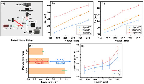
With the experimental setup, the propulsion distances in both axial (ΔH) and lateral (ΔX) directions at different laser powers were investigated for PS particles with diameters of 1, 2 and 4 μm (). The results show that the propulsion distance in both directions increases with increasing laser power and particle size. This is consistent with the theoretical calculation that FS experienced by particles is directly proportional to both laser power and particle size. Furthermore, the motion of PS particles of different sizes was investigated under the action of the Airy beam with varying inner radius (r˜) (). The results indicate that there exists a threshold r˜, above which the particle is trapped by the Airy beam instead of being propelled, and this threshold is dependent on the particle size. Since particle trapping is achieved when the total optical forces equal zero, the threshold r˜ represents the lower bound at which FS + FG = 0 is attainable. The size-dependent nature of the threshold, in turn, suggests that the conditions for FS + FG = 0 vary for different particle sizes. An Airy beam with a specific r˜ value enables the trapping of particles of one size while simultaneously propelling particles of a different size, as the threshold r˜ varies among particles of different sizes. For example, using an Airy beam with r˜ = 0.5, it is possible to trap 4 μm particles in place while propelling 2 μm particles away, thus facilitating selective clearing of particles based on their size. In this scenario, accurate sorting relies on the stable trapping of particles in the Airy beam. The trapping stiffness of Airy beams was investigated using equipotential analysis (see Methods for details).[Citation29,Citation30] shows the trapping stiffness of an Airy beam with r˜ = 0.5 as a function of laser power for 4 μm particles. Similar to Gaussian traps, the stiffness of Airy traps increases with laser power, suggesting the potential for achieving stable trapping by increasing the power. These findings demonstrate the Airy beam’s ability to propel particles of different sizes, facilitating effective sorting and versatile manipulations. Based on these results, several sorting strategies were developed and implemented, which will be presented in the following sections.
2.2. Selective clearing and size-based sorting
Based on the aforementioned theoretical analysis and preliminary experiments, we employed an Airy beam with a power of 130 mW to achieve sorting of 2 μm and 4 μm PS particles by propelling them to heights of ΔH1 = 28 μm and ΔH2 = 44 μm above the initial surface, respectively (see Video S1 of Supplementary Materials). The r˜ and θ of the sorting Airy beam were set to 0.2 and 0.75π, respectively, and the propulsion of the particles was achieved by moving the sample stage. The results confirm the effectiveness of the proposed method in size-based sorting along the z-axis. Moreover, by setting r˜ to 0.5, which lies precisely between the threshold r˜ values for 2 μm and 4 μm particles, the 4 μm microparticle was trapped by the beam, while the 2 μm particle was propelled to a different plane (). Exploiting this effect, selective clearing of 2 μm particles from a mixture of 2 μm and 4 μm particles was achieved by moving the sample stage with the Airy beam constantly on (). After the clearing process, the 4 μm particles remained at the original plane, while the 2 μm particles were propelled to a height of approximately 21 μm above the original plane. The detailed selective clearing procedure is shown by Video S2 in Supplementary Materials.
Figure 3. Selective clearing and size-based sorting. (a1) A 4 μm particle being trapped by the Airy beam with an inner radius () of 0.5 while a 2 μm propelled by the same Airy beam. (a2-a4) Selective clearing of 2 μm particles from a mixture of 2 μm and 4 μm particles. (b1) Six PS particles with diameters of 1 μm, 2 μm, and 4 μm randomly distributed within the trapping region of the HOT. (b2-b4) Particles with diameters of 2 μm, 1 μm, and 4 μm distributed at (b2) ΔH = 0, (b3) ΔH1 = 20 μm, and (b4) ΔH2 = 43 μm, respectively, after sorting by the transition from Gaussian beams to Airy beams.
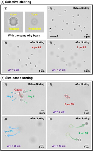
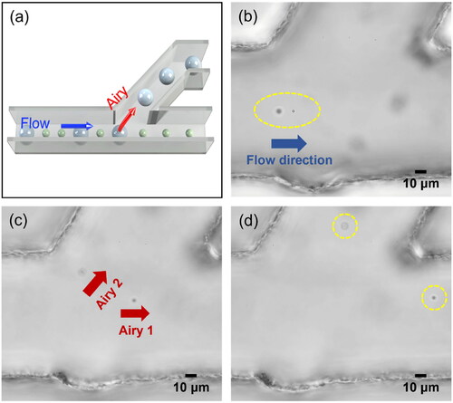
Figure 4. Optofluidic sorting in microfluidic system. (a) Schematic of optofluidic sorting of 2 μm and 4 μm PS particles. (b, c) 2 μm and 4 μm particles were propelled into different heights and directions with = 0.5, θ = 0.25π and
= 0.2, θ = 0.5π, respectively. (d) The 2 μm and 4 μm particles were sorted into the top and bottom channels, respectively.
We then extended the particle sorting process to propel particles of three different sizes to distinct heights and lateral positions using Airy beams and wavefront manipulation. Six PS particles with diameters of 1 μm, 2 μm, and 4 μm—2 particles at each size—were randomly distributed within the trapping region of the HOT (). We initially trapped all particles utilizing Gaussian beams, with the aim of aggregating them all within the same z-plane to refine the spatial precision of the sorting. Subsequently, the Gaussian beams that trapped 1 μm and 4 μm particles were simultaneously remodulated to Airy beams with an inner radius r˜ of 0.2 and propelled them to different heights above the original plane. Throughout the particle propulsion by the Airy beams, the 2 μm particles remained trapped by Gaussian beam to mitigate the influence of scattering forces. Upon completion of the sorting process, the trapping light was turned off, and the 2 μm PS particles remained on the original plane (ΔH = 0, ). On the other hand, the 1 μm and 4 μm particles were observed at z-planes with a height difference of ΔH1 = 20 μm and ΔH2 = 43 μm from the original plane, respectively ()). The detailed sized-based sorting procedure is shown by Video S3 in Supplementary Materials. The utilized incident laser power was 780 mW in total (130 mW per trap). Higher incident laser power enables the propulsion of particles to higher axial positions, as indicated by . Notably, within the measured range, variations in the incident laser power have minimal impact on the relative height between the two sorted particles. The presented sorting experiments showcased the capabilities of microparticle sorting with Airy beams. Additionally, with the synergy of real-time wavefront modulation, much more versatile sorting methods employing multiple focal points and beam modes can be developed, expanding the application potential of the proposed method. Theoretically, size-based sorting and selective clearing could also be achieved by trapping target particles with Gaussian beams and vertically moving the sample stage. However, this approach is time-consuming and may lead to the unintended trapping of other particles during the manipulation process. Moreover, prolonged laser irradiation poses a significant risk of inducing phototoxicity, which can detrimentally affect the integrity of the sample if the method is applied to biological specimens.
2.3. Optofluidic sorting in microfluidic system
In addition to the sorting methods conducted in a static liquid environment, as mentioned above, sorting tasks can also be performed within microfluidic systems by utilizing the variance in threshold r˜ for different particle sizes and direction angles θ. Specifically, leveraging the fact that Airy beams can propel particles and induce both axial and lateral motion during the propulsion process, an optofluidic sorting method was developed within Polymethylmethacrylate (PMMA) microfluidic channels (width: 100 μm, height: 80 μm) (). A mixture solution containing 2 μm and 4 μm PS particles was injected into the channel with a flow rate of 14 μm/s, via a silicone tube connected to a single-channel syringe pump (QHZS-001A, which was modified to reach a linear velocity of 0.08 μm/s). Due to the threshold r˜ values being different for particles of various sizes, the procedure for sorting particles in microfluidic channels can be described as follows: initially, an Airy beam with a relatively large r˜ was employed, which can propel smaller particles while trapping larger ones. Next, when a larger particle was trapped, the Airy beam’s r˜ and θ were reassigned to other values, propelling the larger particle to a different channel. As a result, particles of different sizes were sorted into separate channels. This procedure can be executed either manually or automatically with periodic modulation of the Airy wavefront. Specifically, as showcased in , we initially set the Airy beam with r˜ = 0.5 and θ = 0.25π, which can propel the 2 μm particles in the x-z plane and sort them into the bottom channel. Consequently, when the 2 μm particle passed, it was propelled by the Airy beam, whereas a passing 4 μm particle was be trapped. When a 4 μm particle entered the sorting region, it was trapped (), and the Airy beam was changed to r˜ = 0.2 and θ = 0.5π, which propelled the 4 μm particle in the y-z plane and sorted it into the top channel (), resulting in the top channel containing only 4 μm particles while the bottom channel containing only 2 μm ones (). Notably, fast or even real-time computer-generated hologram (CGH) calculation is crucial for rapid manipulation of light fields and enhancing sorting efficiency with Airy beams. To achieve this, we employed GPU-based parallel computation and CUDA-OpenGL interoperability techniques, which enabled fast hologram calculation that reaches and even surpasses the refresh rate limit of the SLM (see Methods for details).
It is important to note that the experiment was conducted using a relatively low flow rate, which was deliberately chosen to ensure that the particles passing through the Airy beam were exposed to the optical force for a sufficient duration, allowing their motion trajectory to be effectively altered. While increasing the flow rate may potentially enhance the sorting efficiency, it can also lead to a reduction in sorting effectiveness. This is due to the inability to manipulate particles in a timely manner or propel them properly, caused by excessive fluidic speed and forces. However, several approaches can be implemented to improve the sorting efficiency. For instance, by employing target recognition techniques, the spatial positions of particles with various sizes can be rapidly identified.[Citation29,Citation30] Consequently, Airy and Gaussian focal points can be established at these positions using holographic wavefront manipulation and real-time CGH generation. This enables more precise generation of the Airy beam with specific parameters (r˜ and θ) at the corresponding positions, thereby reducing the impact of liquid flow velocity on sorting accuracy.
3. Conclusion
We propose and demonstrate an optofluidic approach for microparticle sorting that leverages the unique properties of Airy beams in optical manipulation. By harnessing the non-diffracting nature and transverse gradient force of Airy beams, we have successfully sorted microparticles of varying sizes into distinct heights and lateral positions. Moreover, the integration of computer-generated holograms and wavefront modulation techniques allows for versatile microparticle sorting by seamlessly switching between Gaussian and Airy beam modes. The efficacy of the sorting method has been further validated through the successful sorting of microparticles within microfluidic channels. This approach offers a highly effective and adaptable solution for microparticle sorting, presenting a robust optofluidic tool for applications demanding precise and efficient sorting of microparticles while preserving sample integrity. The proposed method also holds potential for applications in fields requiring advanced particle manipulation techniques.
4. Methods
4.1. Simulations
Simulations of Airy beams were performed using COMSOL Multiphysics 6.1 with the radio frequency module (electromagnetic wave, frequency domain) and perfectly matched layer boundary conditions. The trapping laser was configured as an Airy beam with a wavelength of 1064 nm. Polystyrene (PS) microparticles with diameters of 1, 2 and 4 μm were simulated. The refractive indices of water and PS microspheres were set to 1.33 and 1.59, respectively. Mesh sizes of 80 nm for the water medium and 50 nm for the PS microspheres were employed in the simulations.
4.2. Generation of Airy beams
Airy beams were generated by loading a cubic phase term onto the SLM.[Citation22] Specifically, for an Airy beam centered at the phase loaded on the j-th pixel of the SLM,
is given by:
where λ is the laser wavelength, f is the focal length of the objective,
is the radius of the SLM aperture,
are the coordinates of the j-th pixel on the SLM,
are the rotated coordinates of the j-th pixel on the SLM, which is expressed as:
and
(inner radius) is a dimensionless constant. The parameter
controls the non-diffractive propagation distance of the Airy beam, with r˜ = 0 corresponding to the ideal non-diffraction state and r˜ → ∞ corresponding to total degradation into a Gaussian beam. In other words,
controls Airy beam generation in a manner similar to a truncation factor.[Citation22,Citation31,Citation32] When generating multiple beams (foci), iterative optimization methods, such as the weighted Gerchberg-Saxton algorithm, were employed to obtain optimal hologram performance.[Citation20,Citation33]
4.3. Stiffness calibration
The entire stiffness measurement process consists of two parts: particle trajectory extraction based on video analysis[Citation29] and stiffness calibration based on equipotential analysis.[Citation30] Videos were captured at a frame rate of 600 fps in uncompressed Audio Video Interleave (AVI) format to ensure a high capturing frame rate. Bead positions were extracted from each frame in the video using the binarization method.[Citation34] This method transforms the bead image into a binary ring and calculates the centroid by averaging the coordinates of non-zero pixels within the ring. The resulting centroid positions were then converted into micrometers by dividing by the pixel resolution of the microscope (∼17 pixels/μm with a 60× objective and the camera used). The x- and y-axis positions corresponded to the column and row numbers on the camera, respectively, and were used to construct the bead trajectory over time using timestamps from the video frames. The equipotential analysis method was utilized as the technique for determining the stiffness of the optical traps. In this approach, the trajectory of trapped beads was recorded for 20 to 30 seconds to accumulate sufficient data, and the stiffness of the trap was derived from the distribution of bead positions. By analyzing the spatial distribution of the trapped particle’s positions, the equipotential analysis method provides a robust and reliable estimation of the optical trap stiffness.
4.4. Hologram generation with GPU and CUDA-OpenGL interoperability
Hologram generation primarily involves calculating the phase value for each pixel on the SLM. By utilizing parallel computation on graphics processing units (GPUs), this process can be significantly accelerated. The calculation of phase values can be considered an elementwise operation, a common technique in GPU computing. This approach allows computations to be divided into smaller subsets or conducted independently using parallel kernel functions, resulting in substantially reduced computation times. Furthermore, leveraging CUDA-OpenGL interoperability further enhances the speed of hologram generation. This interoperability enables data calculated by CUDA (on the GPU) to be seamlessly used for rendering with OpenGL, an application programming interface commonly used for graphics rendering. Since many SLMs, including the one employed in this study, are treated as mini displays by personal computers, CUDA-OpenGL interoperability allows hologram computation and rendering to occur directly within the GPU. This approach eliminates the need for memory transfer between the GPU and central processing unit (CPU), except for the transfer of input parameters.
| Nomenclature | ||
| HOT | = | Holographic optical tweezer |
| CGH | = | Computer-generated hologram |
| SLM | = | Spatial light modulator |
| λ | = | Laser wavelength |
| f | = | Objective's focal length |
| rSLM | = | SLM's aperture radius |
| ϕj | = | Phase loaded on the SLM |
| AVI | = | Audio Video Interleave |
| GPU | = | Graphics processing units |
| CPU | = | Central processing unit |
| TL | = | Tube lens |
| P | = | Linear polarizer |
| PC | = | Personal computer |
| FS | = | Scattering force |
| FG | = | Gradient force |
| FO | = | Optical forces |
| θ | = | Direction angle |
| r̃ | = | Inner radius |
| ΔH | = | Axial direction |
| ΔX | = | Lateral direction |
| n | = | Surface normal vector |
| <TM> | = | Time-independent Maxwell stress tensor |
| Q | = | Unit dyadic |
| ε | = | Electric permittivity |
| μ | = | Magnetic permeability |
| PS | = | Polystyrene |
| PMMA | = | Polymethylmethacrylate |
video S1.gif
Download GIF Image (17.9 MB)
Video S3.gif
Download GIF Image (9.7 MB)
video S2.gif
Download GIF Image (35.1 MB)
Additional information
Funding
References
- De, M.; Ghosh, P. S.; Rotello, V. M. Applications of nanoparticles in biology. Adv. Mater. 2008, 20, 4225–4241. DOI: 10.1002/adma.200703183.
- Qian, W.; Zhang, Y.; Chen, W. Capturing cancer: emerging microfluidic technologies for the capture and characterization of circulating tumor cells. Small 2015, 11, 3850–3872. DOI: 10.1002/smll.201403658.
- Chen, X.; Lv, H. Intelligent control of nanoparticle synthesis on microfluidic chips with machine learning. NPG Asia Mater. 2022, 14, 69. DOI: 10.1038/s41427-022-00416-1.
- Burke, J. M.; Zubajlo, R. E.; Smela, E.; White, I. M. High-throughput particle separation and concentration using spiral inertial filtration. Biomicrofluidics 2014, 8, 024105. DOI: 10.1063/1.4870399.
- Fouet, M.; Mader, M.-A.; Iraïn, S.; Yanha, Z.; Naillon, A.; Cargou, S.; Gué, A.-M.; Joseph, P. Filter-less submicron hydrodynamic size sorting. Lab Chip. 2016, 16, 720–733. DOI: 10.1039/c5lc00941c.
- Gu, Y.; Chen, C.; Mao, Z.; Bachman, H.; Becker, R.; Rufo, J.; Wang, Z.; Zhang, P.; Mai, J.; Yang, S.; et al. Acoustofluidic centrifuge for nanoparticle enrichment and separation. Sci. Adv. 2021, 7, eabc0467. DOI: 10.1126/sciadv.abc0467.
- Zhang, N.; Zuniga-Hertz, J. P.; Zhang, E. Y.; Gopesh, T.; Fannon, M. J.; Wang, J.; Wen, Y.; Patel, H. H.; Friend, J. Microliter ultrafast centrifuge platform for size-based particle and cell separation and extraction using novel omnidirectional spiral surface acoustic waves. Lab Chip. 2021, 21, 904–915. DOI: 10.1039/d0lc01012j.
- Wu, Y.; Chattaraj, R.; Ren, Y.; Jiang, H.; Lee, D. Label-free multitarget separation of particles and cells under flow using acoustic, electrophoretic, and hydrodynamic forces. Anal. Chem. 2021, 93, 7635–7646. DOI: 10.1021/acs.analchem.1c00312.
- Tayebi, M.; Yang, D.; Collins, D. J.; Ai, Y. Deterministic sorting of submicrometer particles and extracellular vesicles using a combined electric and acoustic field. Nano Lett. 2021, 21, 6835–6842. DOI: 10.1021/acs.nanolett.1c01827.
- Xu, X.; Yang, Y.; Chen, L.; Chen, X.; Wu, T.; Li, Y.; Liu, X.; Zhang, Y.; Li, B. Optomechanical Wagon-Wheel effects for bidirectional sorting of dielectric nanoparticles. Laser Photon. Rev. 2021, 15, 2000546. DOI: 10.1002/lpor.202000546.
- Pin, C.; Otsuka, R.; Sasaki, K. Optical transport and sorting of fluorescent nanodiamonds inside a tapered glass capillary: optical sorting of nanomaterials at the Femtonewton scale. ACS Appl. Nano Mater. 2020, 3, 4127–4134. DOI: 10.1021/acsanm.0c00274.
- MacDonald, M. P.; Spalding, G. C.; Dholakia, K. Microfluidic sorting in an optical lattice. Nature 2003, 426, 421–424. DOI: 10.1038/nature02144.
- Nan, F.; Yan, Z. Optical sorting at the single-particle level with single-nanometer precision using coordinated intensity and phase gradient forces. ACS Nano. 2020, 14, 7602–7609. DOI: 10.1021/acsnano.0c03478.
- Woerdemann, M.; Alpmann, C.; Esseling, M.; Denz, C. Advanced optical trapping by complex beam shaping. Laser Photon. Rev. 2013, 7, 839–854. DOI: 10.1002/lpor.201200058.
- Luo, H.; Fang, X.; Li, C.; Dai, X.; Ru, N.; You, M.; He, T.; Wu, P. C.; Wang, Z.; Shi, Y.; et al. 1 nm-resolution sorting of sub-10 nm nanoparticles using a dielectric metasurface with toroidal responses. Small Science 2023, 3, 2300100. DOI: 10.1002/smsc.202370017.
- Zhang, T.; Mahdy, M. R. C.; Liu, Y.; Teng, J. H.; Lim, C. T.; Wang, Z.; Qiu, C.-W. All-optical chirality-sensitive sorting via reversible lateral forces in interference fields. ACS Nano. 2017, 11, 4292–4300. DOI: 10.1021/acsnano.7b01428.
- Lin, W.-Y.; Lin, Y.-H.; Lee, G.-B. Separation of micro-particles utilizing spatial difference of optically induced dielectrophoretic forces. Microfluid. Nanofluid. 2010, 8, 217–229. DOI: 10.1007/s10404-009-0457-y.
- Lee, K. S.; Palatinszky, M.; Pereira, F. C.; Nguyen, J.; Fernandez, V. I.; Mueller, A. J.; Menolascina, F.; Daims, H.; Berry, D.; Wagner, M.; et al. An automated raman-based platform for the sorting of live cells by functional properties. Nat. Microbiol. 2019, 4, 1035–1048. DOI: 10.1038/s41564-019-0394-9.
- Liu, S.; Qu, Z.; Zhao, X.; Wang, J.-L. Fast and versatile optical force measurement with digitally modulated stimulus in holographic optical tweezers. Optics Laser Technol. 2023, 167, 109809. DOI: 10.1016/j.optlastec.2023.109809.
- Qu, Z.; Liu, S.; Fan, X.; Fang, C.; Wang, J.-L.; Zhao, X. Optimized Hologram Generation Method for Real-Time Spontaneous Manipulation. AIP Adv. 2023, 13, 095216. DOI: 10.1063/5.0162458.
- Baumgartl, J.; Mazilu, M.; Dholakia, K. Optically mediated particle clearing using airy wavepackets. Nature Photon. 2008, 2, 675–678. DOI: 10.1038/nphoton.2008.201.
- Siviloglou, G. A.; Broky, J.; Dogariu, A.; Christodoulides, D. N. Observation of accelerating airy beams. Phys. Rev. Lett. 2007, 99, 213901. DOI: 10.1103/PhysRevLett.99.213901.
- Baumgartl, J.; Hannappel, G. M.; Stevenson, D. J.; Day, D.; Gu, M.; Dholakia, K. Optical redistribution of microparticles and cells between microwells. Lab Chip. 2009, 9, 1334–1336. DOI: 10.1039/b901322a.
- Moradi, H.; Jabbarpour, M.; Abdollahpour, D.; Hajizadeh, F. 3D optical trapping by a tightly focused circular airy beam. Opt. Lett. 2022, 47, 4115–4118. DOI: 10.1364/OL.464052.
- Efremidis, N. K.; Chen, Z.; Segev, M.; Christodoulides, D. N. Airy beams and accelerating waves: an overview of recent advances. Optica 2019, 6, 686–701. DOI: 10.1364/OPTICA.6.000686.
- Makris, K. G.; Kaminer, I.; El-Ganainy, R.; Efremidis, N. K.; Chen, Z.; Segev, M.; Christodoulides, D. N. Accelerating diffraction-free beams in photonic lattices. Opt. Lett. 2014, 39, 2129–2132. DOI: 10.1364/OL.39.002129.
- Yang, Y.; Ren, Y.-X.; Chen, M.; Arita, Y.; Rosales-Guzmán, C. Optical trapping with structured light: a review. Adv. Photon. 2021, 3, 034001. DOI: 10.1117/1.AP.3.3.034001.
- Zhang, P.; Prakash, J.; Zhang, Z.; Mills, M. S.; Efremidis, N. K.; Christodoulides, D. N.; Chen, Z. Trapping and guiding microparticles with morphing autofocusing airy beams. Opt. Lett. 2011, 36, 2883–2885. DOI: 10.1364/OL.36.002883.
- Richardson, A. C.; Reihani, S. N. S.; Oddershede, L. B. Non-harmonic potential of a single beam optical trap. Opt. Express. 2008, 16, 15709–15717. DOI: 10.1364/oe.16.015709.
- Florin, E.-L.; Pralle, A.; Stelzer, E. H. K.; Hörber, J. K. H. Photonic force microscope calibration by thermal noise analysis. Appl. Phys. A 1998, 66, S75–S78. DOI: 10.1007/s003390051103.
- Davis, J. A.; Mitry, M. J.; Bandres, M. A.; Ruiz, I.; McAuley, K. P.; Cottrell, D. M. Generation of accelerating airy and accelerating parabolic beams using phase-only patterns. Appl. Opt. 2009, 48, 3170–3176. DOI: 10.1364/ao.48.003170.
- Latychevskaia, T.; Schachtler, D.; Fink, H.-W. Creating airy beams employing a transmissive spatial light modulator. Appl. Opt. 2016, 55, 6095–6101. DOI: 10.1364/AO.55.006095.
- Di Leonardo, R.; Ianni, F.; Ruocco, G. Computer generation of optimal holograms for optical trap arrays. Opt. Express. 2007, 15, 1913–1922. DOI: 10.1364/oe.15.001913.
- Godazgar, T.; Shokri, R.; Reihani, S. N. S. Potential mapping of optical tweezers. Opt. Lett. 2011, 36, 3284–3286. DOI: 10.1364/OL.36.003284.