Abstract
Seven Mg(OEt)2/FeCl3/SiCl4/TiCl4 type procatalysts supported on Mg(OEt)2/FeCl3 mixtures were prepared in order to unravel effect of Fe doping on the catalytic performance in ethylene polymerization. In polymerization experiments, the catalyst based on a support containing an optimum doping amount of 10 wt.% of FeCl3, i.e. C-F10-Si, exhibited an activity 2.4 times greater than that shown by the reference catalyst, C-M. The MW and bulk density of the produced polymers were increased, while the wax amount decreased using doped catalysts. In the next step, the copolymerization of ethylene with 1-hexene was carried out using C-M as reference and C-Fe10-Si as the most efficient procatalysts. In copolymerization experiments, C-Fe10-Si exhibited much higher activity and comonomer incorporation in comparison with reference catalyst. Finally, to shed light on possible interaction of TiCl4 with doped and undoped catalysts, as well as their efficiency in ethylene polymerization, molecular simulation was performed. Energy results revealed that the doping does not alter significantly the capability of the Ti to insert ethylene monomer.
1. Introduction
The use of supports to improve the activity of Ziegler–Natta (ZN) catalysts has been reported since the early 60s.[Citation1–3] Discovery of active MgC12 as an effective support for the fixation of titanium tetrachloride opened a new period in the field of ZN catalysts, both from the industrial and the scientific viewpoints. Because the use of MgC12 as a support drastically enhanced the catalyst activity, a great deal of attention has been focused on the development of various effective supports, such as inorganic compounds.[Citation4,5]
Nowadays, as two kinds of major industrial materials of the carrier, MgCl2·nROH and magnesium ethoxide, Mg(OEt)2, are widely known.[Citation6,7] Although, Mg(OEt)2 has a morphological subject regarding roundness and particle size distribution as compared with MgCl2·nROH, the catalyst made by Mg(OEt)2 shows a higher activity.[Citation8,9]
Industrial catalysts precursors containing magnesium compounds such as MgCl2 or Mg(OEt)2 in conjunction with TiCl3 or TiCl4 showed great performance in olefin polymerization; however, still there are lots of modifications of ZN catalysts varying in the way of preparation of the support [Citation10–14] and differences in the active component compound structure and the presence of various modifying additives.[Citation15–18] Lately, investigations have shown that doping a suitable amount of Lewis acids in MgCl2 or Mg(OEt)2 supports would be an effective way to improve their catalytic performance in α-olefin polymerization. The mostly used doping agents were based on different metal halides such as MnCl2,[Citation2] ZnCl2,[Citation3] NaCl,[Citation4] AlCl3 [Citation5,6,19], and the mixture of metal halide with metalloids like ZnCl2–SiCl4 system.[Citation7,8] These agents not only can have notable effect on catalyst activity but also have the ability to change catalyst efficiency toward higher α-olefins in LLDPE production as well as stereo-regularity of final polymer in propylene polymerization. Furthermore, it was reported that by doping the MgCl2 support with another metal halide that would go into the crystal lattice and cause disorder in it, a disturbance in the setup of active sites is created which leads into the variety in the nature of the active sites and a corresponding variety of chain lengths in the produced polyolefin material.[Citation20,21]
In the present work, we focused on the modification of Mg(OEt)2/TiCl4 type ZN catalyst using FeCl3 as support doping agent and SiCl4 as catalyst modifier in order to expand our knowledge on this important class of olefin polymerization catalysts. To this end, we have prepared seven types of catalysts, using SiCl4 in a constant content and FeCl3 with different amounts. Then, we investigated their efficiency toward catalytic activity in ethylene polymerization and ethylene/1-hexene copolymerization as well as some properties of the polymers obtained thereof. In some cases, to shed light into the possible interaction of FeCl3 doped supports with TiCl4 and also their efficiency in ethylene polymerization, DFT simulation has been performed.
2. Experimental
2.1. Materials
Polymerization grade ethylene with high purity was obtained from Arak Petrochemical Co. (Arak, Iran) and was purified by passing through columns of activated BX and 4 Å molecular sieves. Mg(OEt)2, THF, FeCl3, SiCl4, potassium hydroxide, and titanium tetrachloride (99%) were purchased from Merck (Darmstadt, Germany). Toluene and n-hexane were supplied by Bandar Imam Petrochemical Co. (Mahshahr, Iran), distilled over calcium hydride, and stored over 13X and 4 Å type activated molecular sieves and sodium wire. Triethylaluminum (TEA) and 1-hexene of 93% purity were purchased from Aldrich Chemical Co. (Munich, Germany). Nitrogen gas of 99.99% purity was supplied from Roham Co. (Tehran, Iran), then purified and dried by passage through KOH, activated silica gel and 4 Å molecular sieve columns.
2.2. Preparation of catalysts
2.2.1. Support
The Mg(OEt)2/FeCl3 supports were prepared by mixing a blend of powdered Mg(OEt)2 and FeCl3 (total weight of the support was 10.0 g) in 80 mL of THF under rapid stirring for 8 h under strictly inert atmosphere at 63 °C. After standing for 1 h, the supernatant liquid was removed at room temperature by settling, and the prepared support was dried under N2 atmosphere at P = atmospheric pressure and T = 60 °C within 3 h.
2.2.2. Catalyst
After support synthesis, preparation of the catalysts was accomplished according to a procedure at Ref. [Citation22].
2.2.2.1. Catalyst M
Two grams of magnesium ethoxide and 80 mL toluene were sequentially added into a reactor. After stirring for 30 min at 50 °C at which the mixture formed a homogeneous solution, the temperature was raised to 80 °C. Then, 4 mL TiCl4 was added to the solution at 80 °C. After 2 h, the liquid phase was removed, and the solid residue was washed twice with 100 mL of toluene. Then, a mixture of toluene (100 mL) and TiCl4 (4 mL) was added. The temperature was raised to 120 °C, and the mixture was stirred for another 2 h. The product was washed twice with 100 mL toluene and 4 times with n-hexane to remove unreacted TiCl4. The final catalyst was dried at 70 °C, under a flow of N2 atmosphere in 1 h.
2.2.2.2. Catalyst M-Fn
The Mg(OEt)2/FeCl3 mixed support and 80 mL of toluene treated with molecular sieve were successively added into a reactor. The other steps were the same as those for preparing catalyst M.
2.2.2.3. Catalyst M-Fn–Si
The Mg(OEt)2/FeCl3 mixed support and 80 mL of toluene were successively added into a reactor. After stirring for 30 min at 50 °C, 0.2 mL SiCl4 was added to the solution and stirred for 1 h. The other steps were the same as those for preparing catalyst M-Fn.
2.3. Polymerization of ethylene and copolymerization of ethylene/1-hexene
Ethylene slurry polymerization was performed in a 1-L Buchi stainless steel reactor equipped with a mechanical stirrer (Buchi bmd 300, Switzerland). Before each polymerization experiment, reactor was purged with nitrogen gas at 100 °C for 1.5 h to eliminate moisture and oxygen. After running out of all moisture and air by nitrogen, 500 mL of hexane was added. After 5 min, a required amount of TEAL (Al/Ti = 180) and 5 mg of catalyst were added using syringes. The reactor was heated up to 80–85 °C, and then ethylene was fed to maintain a reactor pressure of 5 bar for 1 h. After the polymerization, reaction was terminated by venting the reactor. The resulting polymer was filtered off and dried in oven at 70 °C for 12 h.
The copolymerization reactions were carried out in the same condition of ethylene polymerization, with this difference that 1-hexene comonomers was injected to the reactor after loading of catalyst.
2.4. Characterization
Crystal structure of the supports was determined by X-ray diffraction (XRD) on a Siemens D-5000 X-ray diffractometer (USA) operating at 40 kV and 25 mA with a copper target (λ = 1.54 Å) and at a scanning rate of 3° min−1. The morphologies of the catalysts and EDX maps were observed by scanning electron microscopy (SEM model S-3000 N, Hitachi, Japan) after coating with a gold sputter coating machine (model E-1010, Hitachi, Japan). The specific surface area of the catalysts was determined by nitrogen physisorption method. The single-point specific surface area of the catalysts was performed on Micrometrics Chemisorb 2750 (USA) at 77 K. Prior to the measurement, the catalyst sample was added into a tube under N2 atmosphere. For determination of Ti content, after sample digestion in H2SO4, Ti was oxidized with H2O2 and analyzed by UV–visible spectrophotometer (λ = 410 nm) in a Shimadzu spectrophotometer model 6800, USA.
The molecular masses and their distributions were determined through high temperature gel permeation chromatography (Waters GPCV 150+, USA), using 1,2,4-trichlorobenzene as the eluent at 140 °C.
The wax amount (the content of soluble part of the produced polymers) was determined through soxhlet extraction for 24 h with hexane solvent. The DSC tests were performed on a DSC Q 1000 of TA (USA), with samples of about 5 mg sealed in aluminum pans, under nitrogen atmosphere in a temperature range between 30 and 180 °C, at a heating rate of 10 °C/min. Melting temperature (Tm) and degree of crystallinity (Xc) were reported from the first heating scan. The degree of crystallinity was calculated via the total enthalpy method, according to the following equation:
where Xc is the degree of crystallinity, ΔHm is the specific enthalpy of melting, and is the specific melting enthalpy for 100% crystalline PE. We used a
value of 288 J/g.[Citation22]
Comonomer content was measured according to Montell test method, MTM 15984E. This method is based on a standard test method, ASTM D 2238 – 68, for absorbance of polyethylene due to methyl groups at 1378 cm−1.[Citation23] The sensitivity of the method is approximately 0.2 wt.% for 1-hexene content.
2.5. Computational details
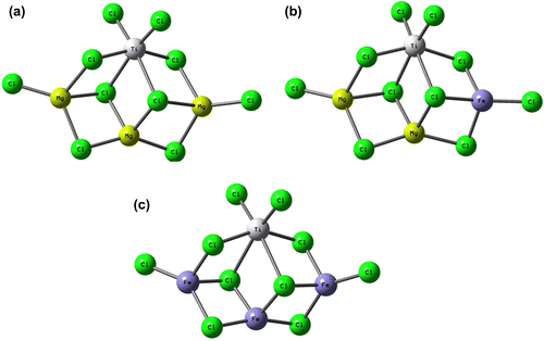
To model the mixed support structure, we considered three model systems: Mg3–Ti4, Mg2Fe–Ti4, and Fe3–Ti4, see Figure , for labels. These systems mainly differ for the numbers of Fe atoms involved in the support structure. In particular, Mg3–Ti4 system can be considered as a good representative model to study TiCl4 adsorption on the (110)-MgCl2 lateral cut. Because of the higher acidity of the 110-lateral cut, the absorption of TiCl4 into this face is more probable than that in 104-lateral cut, and therefore, there is growing evidence that the real active Ti species could have a similar environment.[Citation1,24,25] DFT calculations were performed with the Gaussian 09 package [Citation26] using the BP86 level of theory.[Citation27] In all cases, the electronic configuration of the molecular systems was described with the standard split valence basis set with a polarization function of Ahlrichs and coworkers for H, C, Mg, and Cl (SVP keyword in Gaussian 09).[Citation28] For Ti and Fe, we used the small-core, quasi-relativistic Stuttgart/Dresden effective core potential, with an associated valence basis set (SDD keywords in Gaussian 09).[Citation29] To study the effect of computational level on the obtained data, some test calculations in Table were performed with the HGGA PBEh1PBE functional [Citation30] using triple- ζ valence TZVP basis set.[Citation28]
Figure 1. Model precatalysts used in molecular simulation studies: (a) Mg3–Ti4, (b) Mg2Fe–Ti4, and (c) Fe3–Ti4.
In case of Mg3–Ti(IV), the singlet, and for Mg3–Ti(III) and Mg9–Ti(III) species, the doublet electronic states were used. Differently, for Mg2Fe–Ti(III), Mg8Fe–Ti(III), and Fe3–Ti(III) species, the quartet, and for Fe3–Ti(IV), the nonet electronic states were favored, since Fe usually is in high spin mode and the spins of various Fe atoms in cluster mode are coupled in different ways.
Characterization of the located stationary points as minima or transition state (TS) was performed by frequency calculations. Total energies and optimized geometries are provided in Supplemental data.
3. Results and discussion
3.1. Support and catalyst preparation results
To obtain Mg(OEt)2/FeCl3 mixed supports, Mg(OEt)2 together with different amounts of FeCl3 (see Table ) were dispersed in THF, and then, the supports extracted from the solution by settling and drying under N2 atmosphere.
Table 1. Primary composition of prepared supports.
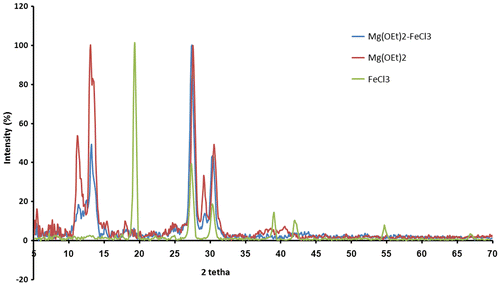
In order to determine in what extent the ability of a support to activate a particular catalyst depends on its crystal structure, primitive Mg(OEt)2, FeCl3, and one of the modified support samples, i.e. S-F5, were characterized by XRD analysis (see Figure ). Primitive Mg(OEt)2 showed sharp peaks centered at 2θ ≈ 11.2, 13.1, 27.5, 29.1, and 30.6 (Figure ). Three peaks at 2θ ≈ 11.2, 13.1, and 29.1 were associated with the crystal structure of Mg(OEt)2, and two large peaks at 2θ = 27.5 and 30.6° were due to polyethylene film, which was used to protect the catalyst from exposure to the atmosphere. After modification of Mg(OEt)2 with FeCl3 to prepare M-Fe5, all FeCl3 peaks disappeared and mixed support showed the same XRD pattern with it in M; however, it was found that the introduction of FeCl3 caused crystalline structural disorder of Mg(OEt)2, attributing to the reduction of the intensity of XRD patterns at 2θ ≈ 11.2, 13.1, and 29.1. It can be deduced from XRD patterns that FeCl3 was dissolved in Mg(OEt)2 and a new FeCl3/Mg(OEt)2 solid solution was formed.[Citation31,32] Such a behavior might be ascribed to the structures in which magnesium was partially replaced by Fe+2 and not Fe+3, since their ionic radii are very similar (Mg2+ = 0.88 Å, Fe+2 = 0.84 Å, and Fe+3 = 0.74 Å).
Final catalysts were prepared by reacting support samples with TiCl4. To this end, two types of catalysts were prepared: (1) The catalysts were synthesized from the simple reaction of S-M, S-F5, S-F10, and S-F15 supports with TiCl4, denoted as C-M, C-F5, C-F10, and C-F15, respectively. (2) Another type of catalysts was prepared from the reaction of S-F5, S-F10, and S-F15 support samples with TiCl4 in the presence of secondary Lewis acid, SiCl4, and named as C-F5-Si, C-F10-Si, and C-F15-Si, respectively. Surface area of the catalyst samples was obtained by BET method and listed in Table . Results showed a significant decrease in the surface area of the catalysts by the addition of FeCl3, in which surface area was decreased from 467.04 m2/g for C-M to 380.24, 312.28, 270.18, 415.62, 280.07, and 228.14 m2/g for C-F5, C-F10, C-F15, C-F5-Si, C-F10-Si, and C-F15-Si, respectively.
Table 2. Analysis of the prepared catalysts.
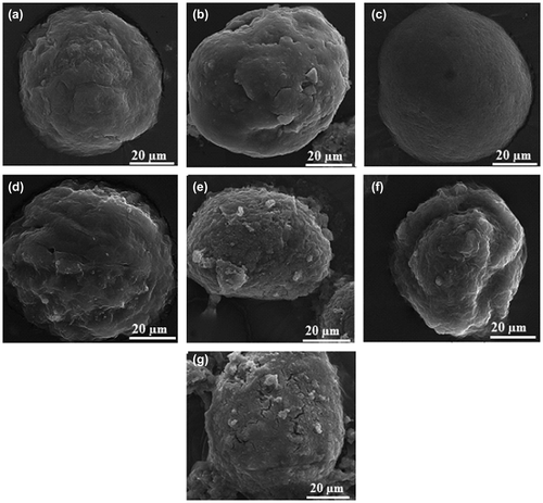
Images of the catalyst morphologies generating from SEM for the synthesized catalysts were shown in Figure (a)–(g). It could be observed that all the catalysts, doped and undoped with Lewis acids, showed almost spherical morphology which resemble a normal catalyst material with mean diameter of about 60 μm.
Figure 3. SEM images of catalysts (a) C-M, (b) C-F5, (c) C-F10, (d) C-F15, (e) C-F5-Si, (f) C-F10-Si, and (g) C-F15-Si.
The surface composition of the obtained catalysts was obtained by EDX analysis and listed in Table . It was suggested before that, during treatment with SiCl4 and TiCl4, Mg(OEt)2 is mainly converted to MgCl2.[Citation33] So, besides Ti, Si, and Fe amounts, we decided to calculate Cl content in the catalyst surfaces, as well. According to the information in Table , catalysts containing FeCl3–SiCl4 mixture showed the highest amount of surface Cl atom.
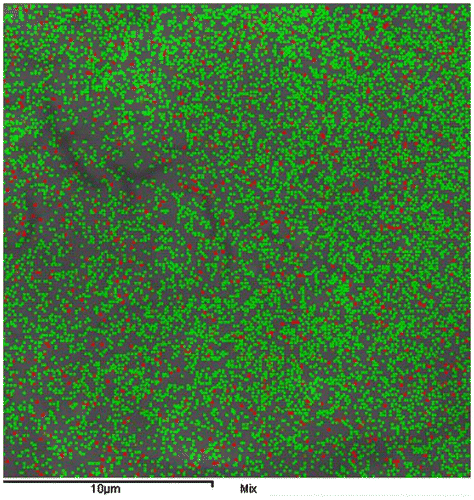
It was also observed that the amount of Si in C-F10-Si was higher than that of it in C-F5-Si and C-F15-Si, even though their amounts were added equally in the catalyst preparation step. Furthermore, there was a difference in the Fe content between primitive amount, which was used in support preparation step, and the amount in the catalyst systems. Fe decrease observed was probably due to the presence in the support as iron alkyl derivatives which were removed in the course of the catalyst synthesis.[Citation31] To see the distribution of Fe on the catalyst surfaces, EDX mapping of catalysts was considered. In all catalyst maps, a nearly homogeneous distribution of Fe on catalyst surface was observed. The EDX mapping of M-Fe5-Si was shown in Figure as a representative picture.
UV–visible technique was used to achieve titanium content of the catalysts (Table ). Results showed a decrease in the Ti content of the samples by applying FeCl3 modifier. Indeed, lowest Ti content was obtained for the catalyst containing a mixture of SiCl4 and highest amount of FeCl3, i.e. C-F15-Si. It is interesting to note that the addition of SiCl4–FeCl3 mixture might reduce free-vacancies of Mg(OEt)2 crystallization and lead to less Ti insertion, which was in agreement with the results of Phiwkliang et al. [Citation34].
3.2. Ethylene polymerization results
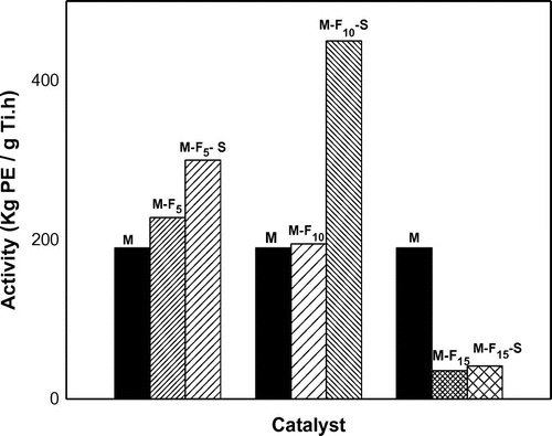
The performance of the catalysts was evaluated in slurry phase polymerization of ethylene using TEA as cocatalyst. Activity results were demonstrated in Figure and Table . As can be seen, the doped catalysts showed an increase in the activity on increasing FeCl3 content up to 0.8 and 1.6 wt.% (expressed as ferrous wt.%) in M-Fe and M-Fe–Si type catalysts, respectively. By going to higher doping concentrations, a drastic drop in the activity was observed. This finding was in line with other researchers results which were published before.[Citation35–37]
Table 3. The activity of different catalysts in ethylene polymerizationTable Footnotea.
Furthermore, it was observed that the activity increase in the presence of FeCl3–SiCl4 mixture was higher than it in the presence of FeCl3 alone. It is possible that besides halogen-donating ability of SiCl4 which acts as promoter in ethylene polymerization, the synergistic effect of double metal halide and metalloid compounds generated more active sites, which were suitable for ethylene polymerization.
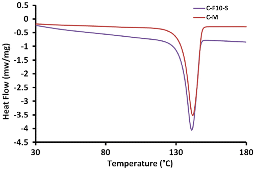
After successive polymerization tests, the obtained polyethylenes were characterized by DSC analysis. DSC curves for all polyethylene samples showed a single peak indicating no appreciable molecular reorganization during heat treatment. Figure shows the representative DSC diagram of samples prepared with C-M and C-F10-Si catalysts. Also, Table shows the influence of various catalytic systems on the Tm and crystallinity (Xc) of the obtained polymers. Results indicated that Tm values of all polyethylenes synthesized from doped catalysts were similar to it in the unmodified catalyst while that Xc changed slightly from 66.9% in the unmodified catalyst to a range of 62.4–69.1% in doped catalysts.
Table 4. Characterization of polyethylenes produced via different catalyst systems.
In addition, the Mn and Mw average molecular weights of the synthesized polyethylenes were measured by the GPC method. The produced analytical results were listed in Table . The presence of the Lewis acid in catalyst showed a trend to give a slight increase in the molecular weight of polyethylenes. This was similar to the results of Pinyocheep et al. [Citation38] and Phiwkliang et al. [Citation34], who found that the molecular weight of PE increases by increasing the amounts of Ti(III) species.
Finally, bulk density of the polymers was measured by a standard 8.1-mL cylindrical vessel and shown in Table . Results revealed that by adding FeCl3 in the support structure, bulk density of the polymers increased, significantly.
3.3. Ethylene/1-hexene copolymerization results
In the next section of this study, we selected C-F10-Si and C-M as the most active and reference procatalysts, respectively, and tested even in ethylene/1-hexene copolymerization experiments in order to assess their ability in the higher α-olefin insertion. The copolymerization results were reported in Table . In line with the homopolymerization results, in the ethylene/1-hexene copolymerization, the doped catalyst showed much higher activity of 577 vs. 185 kg Poly/g Ti∙h in reference catalyst, probably due to the same reasons introduced in the ethylene homopolymerization section.
Table 5. Performance of C-M and C-F10-Si catalysts in ethylene/1-hexene copolymerization.
Furthermore, it was found that, when M-F10-Si is used as catalyst, the activity of ethylene/1-hexene copolymerization increased to 577 kg copoly/g Ti∙h compared with that of ethylene homopolymerization, i.e. 450 kg poly/g Ti∙h. The ‘‘comonomer effect’’ is a curious phenomenon in which the rate of ethylene polymerization is significantly enhanced by the addition of a small amount of α-olefin comonomer, while decreases as the comonomer content in monomer feed increases from an optimum amount.[Citation39,40]
On the other hand, the presence of comonomer lowered the activity of catalyst C-M slightly, from 190 to 185 kg Poly/g Ti∙h, suggesting that the insertion of ethylene was interrupted in this catalyst due to high mole percent of 1-hexene in monomer feed.[Citation39,41]
The copolymers obtained were characterized and the results listed in Table , which collects melting point, percentage of crystalline polymer Xc, and comonomer content. The results showed that the copolymer synthesized with C-M under the same condition, contains a lower amount of 1-hexene than that with doped catalyst. This result confirms that the ability of the catalyst to incorporate bulky comonomer can be improved by doping of MgCl2(ethoxide type) support with FeCl3 due to higher Lewis acidity of FeCl3. This reduces electron density on the active center, which is beneficial to the coordination of more electron-donating-olefin on active center and lead to higher incorporation efficiency.[Citation42]
Table 6. Characterization of ethylene\1-hexene copolymers produced via different catalyst systems.
The DSC analysis was considered at both the first and second heating of the copolymer samples which denoted as 1 and 2 subscripts in the Tm and Xc results, respectively. As can be seen in Table , Tm and Xc were strongly affected by 1-hexene concentration in the copolymer chain so that Tm and Xc of the copolymer produced by C-M catalysts were much higher than them by C-F10-Si catalyst.
3.4. DFT simulation
In the last part of our manuscript, in order to fulfill the lack of a clear characterization data, we employed DFT simulations to assess main interaction occurring in MgCl2- and MgCl2/FeCl3-supported ZN catalytic systems. We chose MgCl2, instead of Mg(OEt)2, since it was observed that during interaction with TiCl4 and SiCl4, it is converted to MgCl2 due to Cl-donating ability of these compounds.[Citation15,43] To study the Ti–Mg and Ti–Fe interactions, we considered three model systems: Mg3–Ti4, Mg2Fe–Ti4, and Fe3–Ti4, see Figure for labels. These systems mainly differ for the numbers of Fe atoms involved in FeCl3/MgCl2 mixed supports. These models were selected according to our XRD and EDX data, and the data in Refs. [Citation31] and [Citation32] which suggested that in MCln (M is metal) doped catalysts, a MCln/MgCl2 solution is formed. DFT studies predicted a clear binding for all systems, with an EBind of −15.1, −9.5, and −4.6 kcal mol−1 for systems Mg3–Ti4, Mg2Fe–Ti4, and Fe3–Ti4, respectively.
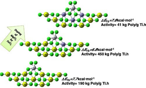
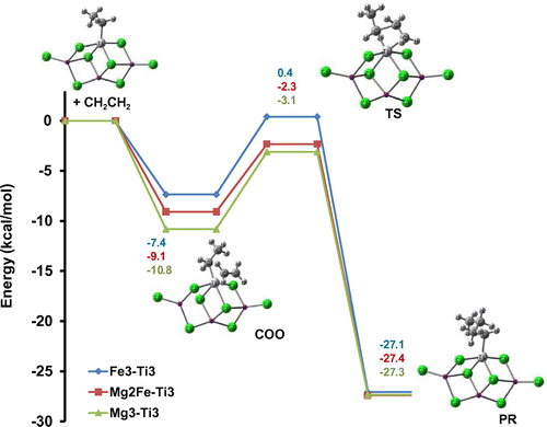
In the next section, to compare better the ability of MgCl2/TiCl4 and MgCl2/FeCl2/TiCl4 catalytic systems in ethylene insertion, DFT studies were employed. In order to model ethylene polymerization using different Fe-doped ZN catalysts, three different small-sized model active centers, i.e. Mg3–Ti3–C2H5, Mg2Fe–Ti3–C2H5, and Fe3–Ti3–C2H5 were utilized. Energy diagrams for ethylene insertion using different model catalysts were shown in Figure . The complexation of the monomer with the Ti active center was barrier less and led to 10.8, 9.1, and 7.4 kcal mol−1 energy gains, for catalysts Mg3–Ti3–C2H5, Mg2Fe–Ti3–C2H5, and Fe3–Ti3–C2H5, respectively. Then, it passed through a four-member ring structure, which turned out to be the TS. A barrier of 7.7, 6.8, and 7.8 kcal mol−1 had to be overcome in order to insert the entering monomer into the Ti–C bond in the catalysts Mg3–Ti3–C2H5, Mg2Fe–Ti3–C2H5, and Fe3–Ti3–C2H5, respectively. The final products were characterized and found to be nearly isoenergetic in all cases. These results indicated that by partially doping of MgCl2 with Fe, although the coordination energy was increased, insertion of ethylene required rather smaller activation energy, 6.8 vs. 7.7 kcal mol−1. Concluding this section, calculations suggest that different catalysts have rather similar insertion barriers (within 1 kcal mol−1). This indicates that the doping does not alter significantly the capability of the Ti to insert ethylene monomer.
Figure 7. Relative energy profiles for ethylene polymerization using Mg3–Ti3–C2H5, Mg2Fe–Ti3–C2H5, and Fe3–Ti3–C2H5 model catalysts with BP86/SVP level of calculation.
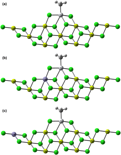
After having explored the effect of doping amount on the energy profile of ethylene insertion, we have tried to study the effect of MgCl2 cluster size on the monomer insertion barrier. Furthermore, besides cluster size, effect of possible doping positions on the TS energy of ethylene insertion was studied, as well. Here, for the sake of brevity, we focused only on the TS energies, while coordination and insertion steps were not considered. For these calculations, we abandoned small (MgCl2)3 model and used a more realistic model containing a cluster with 9 MgCl2 units. Our studied models were shown in Figure (a)–(c). Figure (a) is a representative model of undoped catalyst, while Figure (b) and (c) differ in the location of Fe atom, relative to the Ti active center, among MgCl2 surface. Calculation results with BP86/SVP level of theory showed that a barrier of 6.8, 5.8, and 6.8 kcal mol−1 have to be overcome in order to insert ethylene monomer into Ti–C bond in the Mg9–Ti3–CH3, Mg8Fe–Ti3–CH3, and Mg8Fe–Ti3–CH3-2 model catalysts, respectively. From these data, one can conclude that, although changing cluster size affected TS absolute values (from 7.7 to 6.8 and from 6.8 to 5.8 kcal mol−1), ΔETS, i.e. TS energy difference between undoped and doped catalysts, remained unchanged (nearly 1 kcal mol−1). Further, models have been proposed that explain in a simple way the monomer insertion promotion by Fe doping agent, when located in the near proximity of a TiCl4 molecule adsorbed on the MgCl2 surface.
Figure 8. Medium-sized model catalysts used in molecular simulation, (a) Mg9–Ti3–CH3, (b) Mg8Fe–Ti3–CH3, and (c) Mg8Fe–Ti3–CH3-2.
To test whether the energy barrier of the TSs could depend on the chosen GGA BP86 functional, we localized the TSs with the HGGA PBEh1PBE functional, since we found earlier that it gives the best performance in reproducing the main interactions occurring in ZN catalytic systems.[Citation1] The results were tabulated in Table . Also, in this case, ETS of ethylene insertion in Mg8Fe–Ti3–CH3 model was 1.0 kcal mol−1 lower in energy than that in Mg9–Ti3–CH3 model. Then, the numbers we calculated indicate that the difference between the TSs energies in undoped and doped catalysts is somewhat independent from the computational approach used.
Table 7. TS energy barriers for the insertion of ethylene into different model catalysts with BP86/SVP and PBEh1PBE/TZVP level of calculation.
We also studied the effect of Fe doping on the electron density of Ti active center, in different model catalysts of Figure . The Mulliken charges on Ti in the active catalysts on moving from Mg3–Ti3–C2H5 to the Mg2Fe–Ti3–C2H5 and Fe3–Ti3–C2H5 active centers increased from −0.349 to −0.189 and −0.035, respectively. This increase in the Mulliken charge could be responsible for the activity increase in partially doped catalyst, while that in highly doped catalyst, it seems that other factors rather that charge density on Ti may play main role.
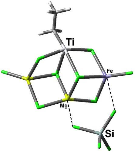
As the final step, we tried to explore possible role of SiCl4 in activity increase of ZN catalyst. The model catalyst that we selected for the coordination of SiCl4 into active catalyst was shown in Figure . By attaching SiCl4 molecule to our model catalyst, the Mulliken charge on Ti decreased from −0.189 in uncoordinated system to the −0.206 in SiCl4 coordinated system. We can conclude from these data that SiCl4 role in activity increase of the modified catalysts is not related to its Lewis acidic property, but can be due to its Cl-donating ability since the homolytic dissociation energy of C–Cl bond in chlorocyclohexane, which has been known as the most efficient activator,[Citation15] is only 8.2 kcal mol−1 lower than homolytic dissociation of Si–Cl bond in SiCl4 (84.5 vs. 92.7 kcal mol−1). So from this section, we can conclude that SiCl4 role in the activation of ZN catalysts can be due to its oxidizing ability in reactivating Ti(II) center by oxidizing it into Ti(III) and Ti(IV), reintroducing it into the active cycle. Reactivation of Ti(II) centers by Cl-containing molecules was fully studied in our previous article [Citation24] and is not more considered here.
4. Conclusion
In this study, first novel carrier materials were synthesized by doping Mg(OEt)2 with different amounts of FeCl3. Then, final catalysts were prepared by reacting support samples with TiCl4. In this way, two types of catalysts were prepared: (1) Catalysts synthesized from the simple reaction of the supports with TiCl4 were denoted as C-M, C-F5, C-F10, and C-F15. (2) Another type of catalysts was prepared from the reaction of the support samples with TiCl4 in the presence of secondary Lewis acid, SiCl4, and named as C-F5-Si, C-F10-Si, and C-F15-Si, respectively. Then, their efficiency was investigated toward catalytic activity in ethylene polymerization as well as some properties of the polymers obtained thereof. Catalytic activity in ethylene polymerization was in the sequence of C-F10-Si > C-F5-Si > C-F5 > C-F10 > C-M > C-F15 > C-F15-Si. Furthermore, characterization of the polymers showed that catalyst modification increases the bulk density and molecular weights, reduces wax amount, but does not affect on the melting temperature of resulting polymers.
In the next step, ethylene/1-hexene copolymerization was carried out using C-M and C-F10-Si as reference and most efficient procatalysts, respectively. Results showed higher activity as well as higher 1-hexene incorporation for modified catalyst in comparison with unmodified one.
In some cases, to shed light on possible interaction of TiCl4 with doped and undoped catalysts, as well as their efficiency in ethylene polymerization, molecular simulation was performed using DFT method. It is the first time that DFT simulation was used to unravel basic interactions in these kinds of catalysts.
Supplemental data
Supplemental data for this article can be accessed here http://dx.doi.org/10.1080/15685551.2015.1041089.
Supplementary Material
Download MS Word (69 KB)Acknowledgments
The authors thank MOLNAC (www.molnac.unisa.it) for its computer facilities and also Jam petrochemical company for comonomer content analysis.
Disclosure statement
No potential conflict of interest was reported by the authors.
Additional information
Funding
References
- Correa A, Bahri-Laleh N, Cavallo L. How well can DFT reproduce key interactions in Ziegler–Natta systems? Macromol. Chem. Phys. 2013;214:1980–1989.10.1002/macp.v214.17
- Arzoumanidis G. Amoco CD commercial polypropylene catalyst tailor-made for the Amoco-Chisso gas phase process. Polyolefins J. 2014;1:131–137.
- Woo JH, Hong SC. Study on immobilized metallocene and single-site catalysts for the preparation of ultra-high molecular weight polyethylene at various polymerization conditions. Polym.-Plast. Technol. Eng. 2011;50:1557–1563.10.1080/03602559.2011.603784
- Xiao A, Zhou S, Zheng Q, Shen Y, Zhang W. Recent research progress of branched and functional branched polyethylene prepared using Ni- and Pd-based catalysts. Polym.-Plast. Technol. Eng. 2010;49:1540–1551.10.1080/03602559.2010.512333
- Rahbar A, Nekoomanesh-Haghighi M, Bahri-Laleh N, Abedini H. Effect of water on the supported Ziegler–Natta catalysts: optimization of the operating conditions by response surface methodology. Catal. Lett. 2015;145:1186–1195.
- Shafiee M, Ramazani SAA. Optimization of UHMWPE/graphene nanocomposite processing using Ziegler–Natta catalytic system via response surface methodology. Polym.-Plast. Technol. Eng. 2014;53:969–974.10.1080/03602559.2014.886067
- Sharma A, Singh S, Singh G, Gupta VK. Polypropylene resin flowability improvement through catalyst morphology. Polym.-Plast. Technol. Eng. 2011;50:418–422.10.1080/03602559.2010.543232
- Tanase S, Katayama K, Inasawa S, Okada F, Yamaguchi Y, Sadashima T, Yabunouchi N, Konakazawa T, Junke T, Ishihara N. New synthesis method using magnesium alkoxides as carrier materials for Ziegler–Natta Catalysts with spherical morphology. Macromol. React. Eng. 2008;2:233–239.10.1002/mren.v2:3
- Németh Sn, Feil B, Árva P, Abonyi J. Effects of catalyst activity profiles on the operating conditions of an industrial polymerization reactor. Polym.-Plast. Technol. Eng. 2006;45:1301–1306.10.1080/03602550600948939
- Hadian N, Hakim S, Nekoomanesh-Haghighi M, Bahri-Laleh N. Storage time effect on dynamic structure of MgCl2.nEtOH adducts in heterogeneous Ziegler–Natta catalysts. Polyolefins J. 2014;1:33–41.
- Ma Z, Wang L, Wang W, Wang J, Yu H. Study of propylene polymerization catalyzed by spherical MgCl2-supported Ziegler–Natta catalyst system: preparation of spherical support. Polym.-Plast. Technol. Eng. 2005;44:1475–1483.10.1081/200065168
- Wang J, Wang L, Feng L, Gu X, Yu H. Studies on synthesis of low isotactic polypropylene by using a novel MgCl2-supported and low Ti-loading catalyst. Polym.-Plast. Technol. Eng. 2005;44:501–510.10.1081/PTE-200048308
- Yu H, Wang L, Ye Z, Ma Z, Jiang S, Wang J, Feng L, Gu X. Study on morphology and particle size distribution of polypropene catalyzed by novel spherical Ziegler–Natta catalyst. Polym.-Plast. Technol. Eng. 2004;43:1115–1128.10.1081/PPT-200030050
- Zhao Z, Wang L, Wang J, Gao H, Yu H, Chen T, Dong X. Study on the microstructures of polypropylene synthesized by a novel MgCl2-supported and low Ti-loading Ziegler–Natta catalyst. Des. Monomers Polym. 2007;10:477–486.10.1163/156855507782401204
- Bahri-Laleh N, Arabi H, Mehdipor-Ataei S, Nekoomanesh-Haghighi M, Zohuri G, Seifali M, Akbari Z. Activation of Ziegler–Natta catalysts by organohalide promoters: a combined experimental and density functional theory study. J. Appl. Polym. Sci. 2012;123:2526–2533.10.1002/app.34589
- Patil HR, Vyas PB, Bhajiwala HM, Gupta V. Alkoxy silanes as external donors for polypropylene procatalyst: study on polymerization performance and effect on resin properties. Polym.-Plast. Technol. Eng. 2012;51:466–472.10.1080/03602559.2011.651241
- Parada A, Rajmankina T, Chirinos J, Morillo A, Fernández JG. Catalytic systems based on TiCl4/MgCl2/SiCl4-n(OR)n for olefin polymerization. Des. Monomers Polym. 2003;6:1–10.10.1163/156855503321127484
- Sun T, Wang L, Dong X, Wang W. An insight into the chain-propagation mechanism of propylene polymerization catalyzed by traditional Ti-based Ziegler–Natta catalysts in view of recently developed catalysts. Des. Monomers Polym. 2006;9:117–127.10.1163/156855506776382691
- Xiao A, Wang L, Liu Q, Yu H, Dong X. Synthesis of low isotactic polypropylene using MgCl2/AlCl3-supported Ziegler–Natta catalysts prepared using the one-pot milling method. Des. Monomers Polym. 2008;11:139–145.10.1163/156855508X298044
- Garoff T, Leinonen T. Mn doping of the Ziegler–Natta PP catalyst support material. J. Mol. Catal. A: Chem. 1996;104:205–212.10.1016/1381-1169(95)00193-X
- Shamiri A, Chakrabarti M, Jahan S, Hussain M, Kaminsky W, Aravind P, Yehye W. The influence of Ziegler–Natta and metallocene catalysts on polyolefin structure, properties, and processing ability. Materials. 2014;7:5069–5108.10.3390/ma7075069
- Bahri-Laleh N, Seifali Abbas-Abadi M, Nekoomanesh -Haghighi M, Akbari Z, Tavasoli MR, Mirjahanmardi SH. Effect of halocarbon promoters on polyethylene properties using MgCl2 (ethoxide type)/TiCl4/AlEt3/H2 catalyst system. J. Appl. Polym. Sci. 2010;117:1780–1786.
- ASTM D 2238 –921999. Standard test methods for absorbance of polyethylene due to methyl groups at 1378 cm−1. ASTM International: West Conshohocken, PA; 2012.
- Bahri-Laleh N, Correa A, Mehdipour-Ataei S, Arabi H, Nekoomanesh-Haghighi M, Zohuri GH, Cavallo L. Moving up and down the titanium oxidation state in Ziegler−Natta catalysis. Macromolecules. 2011;44:778–783.10.1021/ma1023582
- Bahri-Laleh N, Nekoomanesh-Haghighi M, Mirmohammadi SA. A DFT study on the effect of hydrogen in ethylene and propylene polymerization using a Ti-based heterogeneous Ziegler–Natta catalyst. J. Organomet. Chem. 2012;719:74–79.10.1016/j.jorganchem.2012.08.017
- Frisch MJ, Trucks GW, Schlegel HB. Gaussian 09. Pittsburgh (PA); 2009.
- Perdew JP. Density-functional approximation for the correlation energy of the inhomogeneous electron gas. Phys. Rev. B. 1986;33:8822–8824.10.1103/PhysRevB.33.8822
- Schäfer A, Horn H, Ahlrichs R. Fully optimized contracted Gaussian basis sets for atoms Li to Kr. J. Chem. Phys. 1992;97:2571.10.1063/1.463096
- Küchle W, Dolg M, Stoll H, Preuss H. ECP SDD. J. Chem. Phys. 1994;100:7535.10.1063/1.466847
- Ernzerhof M, Perdew JP. Generalized gradient approximation to the angle- and system-averaged exchange hole. J. Chem. Phys. 1998;109:3313–3320.10.1063/1.476928
- Fregonese D, Bresadola S. Catalytic systems supported on MgCl2 doped with ZnCl2 for olefin polymerization. J. Mol. Catal. A: Chem. 1999;145 265–271.10.1016/S1381-1169(99)00015-1
- Chen Y-P, Fan Z-Q, Liao J-H, Liao S-Q. Molecular weight distribution of polyethylene catalyzed by Ziegler–Natta catalyst supported on MgCl2 doped with AlCl3. J. Appl. Polym. Sci. 2006;102:1768–1772.10.1002/(ISSN)1097-4628
- Zohuri GH, Ahmadjo S, Jamjah R, Nekoomanosh M. Structural study of mono- and bi-supported Ziegler–Natta catalysts of MgC12/SiO2/TiC14/donor systems. Iran Polym. J. 2001;10:149–155.
- Phiwkliang W, Jongsomjit B, Praserthdam P. Effect of ZnCl2- and SiCl4-doped TiCl4/MgCl2/THF catalysts for ethylene polymerization. J. Appl. Polym. Sci. 2013;130:1588–1594.10.1002/app.v130.3
- Phiwkliang W, Jongsomjit B, Praserthdam P. Synergistic effects of the ZnCl2–SiCl4 modified TiCl4/MgCl2/THF catalytic system on ethylene/1-hexene and ethylene/1-octene copolymerizations. Chin. J. Polym. Sci. 2014;32:84–91.10.1007/s10118-014-1380-6
- Ribour D, Monteil V, Spitz R. Strong activation of MgCl2-supported Ziegler–Natta catalysts by treatments with BCl3: evidence and application of the “cluster” model of active sites. J. Polym. Sci., Part A: Polym. Chem. 2009;47:5784–5791.10.1002/pola.v47:21
- Chen Y-P, Fan Z-Q. Ethylene/1-hexene copolymerization with TiCl4/MgCl2/AlCl3 catalyst in the presence of hydrogen. Eur. Polym. J. 2006;42:2441–2449.
- Pinyocheep J, Ayudhya SKN, Jongsomjit B, Praserthdam P. Observation on inhibition of Ti3+ reduction by fumed silica addition in Ziegler–Natta catalyst with in situ ESR. J. Ind. Eng. Chem. 2012;18:1888–1892.10.1016/j.jiec.2012.04.018
- Cho HS, Lee WY. Synthesis of inorganic MgCl2–alcohol adduct via recrystallization method and its application in supported organometallic catalysts for the polymerization of ethylene with 1-hexene. J. Mol. Catal. A: Chem. 2003;191:155–165.10.1016/S1381-1169(02)00215-7
- Palza H, Velilla T, Quijada Rl. Dynamic model of the copolymerization of propylene and 1-hexene with the Me2Si(2-Me-Ind)2ZrCl2 catalytic system: effect of 1-hexene concentration. Polym.-Plast. Technol. Eng. 2006;45:1233–1241.10.1080/03602550600887533
- Moreno J, van Grieken R, Carrero A, Paredes B. Ethylene polymerization by metallocene catalysts supported over siliceous materials with bimodal pore size distribution. Macromol. Symp. 2011;302:198–207.10.1002/masy.v302.1
- Senso N, Praserthdam P, Jongsomjit B, Taniike T, Terano M. Effects of Ti oxidation state on ethylene, 1-hexene comonomer polymerization by MgCl2-supported Ziegler–Natta catalysts. Polym. Bull. 2011;67:1979–1989.10.1007/s00289-011-0610-0
- Ghasemi Hamedani N, Behroozi Fard Moghaddam M, Marandi R, Azimfar F, Abedi S, inventors. Ziegler catalyst and method of synthesizing the same patent 2013/0030134 A1. 2013.

