Abstract
In this study, the different encapsulation methods involving emulsification and coaxial electrospinning were both utilized to fabricate a series of core/sheath composite, nanoparticles (NPs) and Nanofibers (NFs) separately, for drug delivery on potential biological and therapeutic applications. Bovine serum albumin (BSA) was employed as an active pharmaceutical ingredient model for core; poly(L-lactic acid) (PLLA) and methoxy poly(ethyleneglycol)-Poly lactic acid (mPEG-PLA) were selected as the encapsulation matrix for sheath. Attributed to the optimized fabrication procedures, the obtained NPs and NFs had the small average diameters and narrow size distributions with uniform structures and smooth surface morphologies. Based on the drug release profiles, both the NPs provided a burst release process followed by a drug diffusion manner, while for the NFs, the drug diffusion was the predominant factor in drug release. In particular, the mPEG-PLA NFs were fabricated with excellent hydrophilicity and highly neutralized surface resulting in a sustained release of BSA over 10 days. In addition, mPEG-PLA NFs also provided a better zero-order drug release profiles during the release time from 8 to 72 h, and a one-dimensional Fickian diffusion pattern during the whole BSA release period. A cytotoxicity study suggested that the two drug delivery systems were both safe to cells. In conclusions, the synergism of PEGylation with coaxial electrospinning may be an effective way to retard the release of drugs in a more sustained manner.
1. Introduction
Drug delivery systems (DDS) originated in the 1960s and have the potential to revolutionize a wide range of medical diagnosis and therapy, such as cardiovascular disease,[Citation1,2] neoplastic disease,[Citation3] even the gene therapy.[Citation4,5] Therefore, in recent years, the development of a controllable DDS that would allow drug/protein to release with appropriate amount at specific sections of human body has become an important field of research. Despite many efforts that have been made in this area, difficulties still arise when an attempt is made to develop biopharmaceuticals or biomedical drugs with an optimal bioavailability and biostability as well as a maximum therapeutic efficiency. Two main challenges [Citation6] are (i) the development of a reliable structure, which would protect drug/protein against complex biological environments induced by the gastrointerstinal tract and first-pass liver effects after oral/vein adminstration before arriving at the targeted sites, or the poor skin permeability due to its low hydration resulting in prolonging the delivering time to the targeted skin sites; and (ii) the achievement of controllable drug release procedure, which would enhance the therapeutic effect and prevent the body from the damage of the exorbitant blood drug level. Therefore, researching for the desired excipients by means of biotechnologies and establishing the optimal DDS are extremely important.
Microencapsulation technology, as a progressive strategy developed for DDS in recent years,[Citation7,8] is speculated to offer an alternative administration route over the conventional ones. Microencapsulation system, as an encapsulated reservoir, involves the sheath and the core layers of structure. The sheath layer is made up of the polymeric matrix to prevent the core layer of active ingredients (as the drug, protein and gene, etc.) from the damages of high temperature or harsh environments such as acidity, alkalinity, oxidation, light, or moisture. Moreover, the sheath layer allows the core active ingredients release in a predetermined profile.
There are various methods used to encapsulate drugs. Generally, these techniques can be conveniently grouped into two major categories: chemical and physical methods; the latter one can be further divided into physico-chemical and physico-mechanical techniques.[Citation9] The selection of the encapsulation methods is based primarily on the water-solubility of drug/protein (most drugs simply falling into hydrophilicity type or lipophilicity type, although there are some intermediates, such as protein). Owing to the surface tension of polymers, the encapsulated reservoir is usually solidified in the form of microparticles (microspheres or microcapsules). A modified solvent multiple emulsion-solvent evaporation technique was reported and used for nanoparticles (NPs) preparation.[Citation10] This technique involves five step to fabricate a series of NPs with high drug loading and small diameter. However, one major drawback to the polymeric microparticles is their tendency to be cleared in the gastrointestinal tract or the first-pass metabolism rapidly, which are susceptible to the microparticles diameters, the ζ-potentials and other surface properties, and so on.[Citation11]
Since the mid-1990s, there has been a growing interest in the production of Nanofibers (NFs) by electrospinning.[Citation12] A basic mechanism of electrospinning is to employ electrostatic repulsions of highly charged polymer jets to produce nano- or microscale fibers laid down randomly and solidified on the collector. Bio-mimicking electrospun NFs with a high surface area to volume ratio and very good mechanical performance have received much attention because of their structural similarity to the extracellular matrix of biological systems such as collagen fibers. Therefore, these important properties are determinant to their use in several applications for biomedical devices, tissue engineering scaffolds, and drug delivery carriers. Particularly in the field of drug delivery, a wide variety of functionalization systems that can be created in terms of encapsulating not only low molecular weight drugs [Citation13] but also macromolecules such as proteins and nucleic acids into electrospun fibers,[Citation14] and the drug release profile for these fibers systems could be controlled in a fiber diameter-dependant manner [Citation15] or other factors.
The difference between the fabrication procedures of microparticles and fibers is straightforward, whereas, the distinction between them becomes vaquer when the release profiles of drug/protein are considered. However, the studies published on this distinction are very few. In this study, we focused on the fabrication and characterization of drug-loaded composites in terms of the NPs and NFs, and highlighted the comparison of the release profiles originating from these two drug delivery routes. Considering the bovine serum albumin (BSA) was an active pharmaceutical ingredient model for drug loading, as well as poly(L-lactic acid) (PLA) and its derivatives have attracted much attention for their biodegradability and biocompatibility in human body, in this study, the NPs/NFs were fabricated in this study with sheath of hydrophobic PLA and hydrophilic methoxy poly(ethyleneglycol)-Poly lactic acid (mPEG-PLA)along with a core of BSA via emulsion–solvent evaporation technique and coaxial electrospinning, separately. The physicochemical properties of NPs and NFs were characterized using water contact angle measurements, scanning electron microscopy (SEM) and dynamic light scattering instrument. The interaction between the NPs/NFs and the cells are also evaluated through the bone marrow derived mesenchymal stem cells (MSCs) culture tests, separately. A fluorescence microscope was used as a tool to characterize the release behaviors of fluorescein isothiocyanate labeled BSA (FITC-BSA). To the end, based on the release mechanism models, we analyzed how the release behaviors of drug/protein depend on the shell polymers categories and dosage forms.
2. Materials and methods
2.1. Materials
Lyophilized BSA, the emulsifiers for NPs (Span80, Tween80) and the solvents dichloromethane, acetic ether, 2,2,2-trifluoroethanol (TFE) (purity ≥ 99.9%), dimethylsulfoxide (DMSO) were all of analytical grade obtained from Sinopharm Chemical Reagent Co., Ltd (Shanghai, China). PLA (Mw = 200 kDa) and mPEG-PLA (70:30, PEG Mn = 5 kDa) were synthesized by Jinan Daigang Biomaterial CO., Ltd. (Jinan, China). Fluorescein isothiocyanate BSA (BSA-FITC) and Coomassie brilliant blue G-250 (CBG-250) were purchased from Sigma Aldrich.
2.2. Preparation of BSA-loaded NPs
NPs containing model drug of BSA were formulated using a modified multiple emulsion–solvent evaporation technique as described previously.[Citation16] In brief, 0.25 g PLA or mPEG-PLA, 0.075 g Span80 and 0.075 g Tween80 were dissolved in mixture of methylene chloride and acetic ether (5 ml) as organic phase. Then an aqueous solution of BSA (0.15 g/ml, 0.5 ml) was emulsified in the organic phase using a probe sonicator (50 W for 15 s) to form a primary oil-in-water emulsion. This initial emulsion was further mixed in the stabilizer of PVA-containing aqueous solution to make a w/o/w double emulsion with a high-pressure homogenizer. After that, the double emulsion was poured into 110 ml water solution and the system was stirred for the removal of the solvent under atmospheric pressure at room temperature.
2.3. Fabrication of BSA-loaded NFs
NFs containing model drug of BSA were fabricated by coaxial electrospinning. The fabrication technique used was similar to the method reported by others.[Citation10,17] Briefly, PLA or mPEG-PLA (0.25 g) was dissolved in TFE (5 ml) to obtain a transparent sheath spinning liquid. Then, BSA (0.075 g) was dissolved in de-ionized water (0.5 ml) to form the core spinning liquid. The coaxial double spinneret consisted of two concentrically arranged capillaries. The inner (core) capillary was a needle with a blunt tip with inner diameter of 0.40 mm and outer diameter of 0.60 mm. The outer (sheath) capillary had an inner diameter of 0.90 mm. Two individual syringes connected to the coaxial spinneret contained certain amounts of sheath and core solutions, separately. Both capillaries were connected to the same high-voltage power supply. Flow rates in the capillaries were controlled using two separate pumps in an electrospinning apparatus. The sheath flow rate was set to 1 ml/h, while the core f1ow rate was 0.2 ml/h. A grounded collector located 20 cm apart from the spinneret. Random NFs were collected by a stainless steel drum, which rotated at 60 rpm. The applied voltage was maintained at 25 kV. All the electrospinning processes were carried out at approximately 25 °C and 45–65% humidity.
2.4. Characterization of NPs and NFs
2.4.1. Morphology
The morphology of the NPs and NFs were observed using SEM (S-3400 N II, HITACHI, Japan). Samples were transferred onto a small metal cylinder and coated with gold prior to examination. In particular for the NFs, the as-spun fibers were collected on the aluminum foils, therefore, the samples for SEM imaging were cut into small sizes with the aluminum foils and sputter coated with platinum prior to SEM.
2.4.2. Size and zeta potential
The size distributions of the NPs suspension were determined at 25 °C by dynamic light scattering (DLS) using a DelsaNano C zeta potential analyzer (Beckman-Coulter, USA). In detail, approximately 100 mg NPs were re-dispersed in 10 ml phosphate-buffer solution (PBS) (pH 7.4) for several minutes using an ultrasonic bath. The particles size analysis was carried out at 25 °C with a wavelength of 667 nm and a detection angle of 90°. The average fiber diameter of NFs was determined from the SEM images using a method published elsewhere.[Citation18]
The surface zeta potential of NPs and NFs were also characterized by DLS using the DelsaNano C zeta potential analyzer which was mentioned above.
2.4.3. Hydrophilicity investigation
Hydrophilicity of the NPs and NFs were both evaluated by measuring the static contact angle of samples films using JJC-1 static contact angle equipment (Changchun No. 5 Optical Instrument Co. Ltd.). For the NPs samples evaluation, the NPs suspension (1 mg/ml millipore water) was spincoated onto a cleaned glass slide (100 × 100 × 1 mm3) at 1500 rpm for 45 s. And then, advancing sessile drop water contact angles were measured. As for the NFs samples preparation, there was much simpler: a droplet of deionized water (10 μL) was dripped onto the membrane surface and the contact angle was measured. In this study, Milli-Q water was used with a drop volume of approximately 0.02 ml. Results are presented as an average of five measurements on at least three different sites.
2.4.4. In vitro cell adhesion and proliferation
Cytotoxicity of the NPs and NFs was determined by 3-(4,5-dimethylthiazol-2-yl)-2,5-diphenyltetrazolium bromide (MTT assay) in human bone-marrow (MSCs). MSCs cell suspensions (100 μl, 2 × 10⁴ cells) were dispensed (four wells for each particle type) into 96-well plates (Costar New York, USA) and incubated overnight (12 h) to allow for cell adherence. Culture medium was replaced with 100 μl of NPs/culture or NFs/culture medium suspensions with different concentrations of 0.03125, 0.0625, 0.125, 0.25, 0.5, 1, and 2 mg/ml and incubated at 37 °C. MSCs without NPs or NFs were used as the control. After 72-h incubation, 30 μl of MTT (5 mg/ml) solution was added into each well and was allowed to react at 37 °C for 4 h. Then, the solution was removed and 100 μl of DMSO was added into each well. The plate was incubated for 15 min at 37 °C and optical densities (OD) at 490 nm was measured with Spectra max PLUS384 (Molecular Devices Corp., USA). The cell viability was calculated by the following formula:(1)
Microscope and SEM were used to examine the morphological characteristics of hMSC-seeded NPs and NFs, separately. The cells cultured samples introduced above were fixed in a 2.5% glutaraldehyde solution. They were dehydrated and sputter-coated with platinum for 5 min before imaging.
2.4.5. Drug release performance
To compare the release kinetics of the BSA from the NPs and NFs, NPs powder and NFs mat were immersed into the release medium (phosphate-buffered solutions, PBS, pH 7.4) seperately. In detail, ~15 mg of the NPs was weighed out and dispersed into 2 ml PBS, and then, the dispersed solution was loaded into a dialysis tube and dialyzed against 15-ml medium. For electrospinning NFs samples, the NFs mats were cut into three pieces in parallel and their weights were accurately measured to ensure the absolute amount of NFs was similar to NPs powder. The samples were then placed in different vials containing 15 ml PBS. All the samples for release experiments were incubated at 37 °C with shaking speed of 70 rpm for a period of 10 days. At the predetermined time intervals, 10 ml of release medium was collected and the same volume of fresh medium was added. The BSA concentrations in the collected release medium were evaluated by Bradford method [Citation19] using a UV–vis spectrophotometer (Perkin Elmer, USA). The characteristic absorption peak at 595 nm for the dye-bind-BSA was monitored. The experiments were done in triplicate.
2.4.6. Qualitative analysis of phagocytic uptake
To assess two systems release behavior more intuitively, the interaction between cells and the released BSA in the release medium was validated by a fluorescence microscope (Nikon TE2000, Nikon Instruments, Melville, NY, USA). It is worth mentioning that FITC labeled BSA was chosen in this experiment.
In vitro uptake of FITC-BSA was carried out using murine peritoneal macrophage cells (MPMs) harvested from ICR mice (weight in 25 ± 1 g). One milliliter Mercaptoacetate was injected into the abdominal cavity of mice. The mice were sacrificed 30 min later, and the peritoneal cells were collected by flushing the peritoneal cavity with 10 ml of 0.9% NaCl. After that, the MPMs were isolated by centrifugation at 1000 rpm for 5 min and re-suspended in complete culture medium. After being transferred to a 24-well plate (1 ml per well), the cells were incubated at 37 °C in atmosphere containing 5% CO2 for 24 h. The purification of macrophages was performed by washing with culture medium to remove non-adherent cells; adherent cells were further incubated in culture medium.
And then, at the indicated time intervals post-release (24, 48 and 72 h), 300 uL of the collected release medium was added and incubated with the MPM at 37 °C for 30 min. The phagocytized cells were observed using the fluorescence microscope.
3. Results and discussion
3.1. Preparation and characterizations of NPs and NFs
For these two encapsulation systems, the shape and size of the samples are governed by several parameters. For NPs, the solvents types, the volume ratio of oil phase to external water phase [Citation20] and emulsification time are the main parameters affecting the performance. In contrast, for NFs, the concentration, viscosity and conductivity of the polymer solution,[Citation9] as well as the voltage and humidity are the main parameters that affect the final characteristics of electrospun NFs. Therefore, the different polymeric systems used to produce the NPs and NFs were characterized and optimized in terms of the above properties in advance (not shown in here).
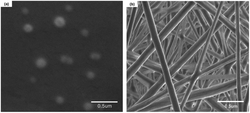
SEM images of NPs fabricated by mPEG-PLA are given in Figure (a). The particles appeared spherical with an average diameter of 189.1 ± 7.8 nm (Table ). It is worth to mention that PLA NPs with the similar particles size and morphology were also been obtained owing to the identical preparation process and parameter, therefore, the image of PLA NPs was not presented here. As listed in Table , the surface electrical potential values, however, of samples were varied with the function of PEGylation pronouncedly. It can be seen that with the PEGylation process, the surface charges of NPs increased from −39.6 ± 7.5 mV to −15.6 ± 2.3 mV. This can be attributed to the PEG coating builds an uncharged wall leading to neutralization of the NPs apparent charges.[Citation21] In addition, the contact angles measurements of pure PLA and copolymer mPEG-PLA in millipore water at 37 °C indicated that the introduction of PEG enhances the hydrophilicity of NPs considerably.
Table 1. The diameter and surface properties of NPs and NFs fabricated by PLA and mPEG-PLA.
The NFs obtained from coaxial electrospinning with a sheath of mPEG-PLA had a smooth surface and uniform structure with narrow diameter distributions of 176.5 ± 16.8 nm (Figure (b)). On the other hand, from the perspective of what is happening with the NFs after PEGylation, the tendency involves surface charges as well as hydrophilicity of materials that were substantially in accordance with those of NPs.
Furthermore, in Table , it obviously appeared that the ζ-potential on the matrix surface would shift from negative to positive when the polymer was subjected to the electrospinning process, no matter PEGylation or not. These results are in accordance with other studies,[Citation22]which could be attributed to the applied voltage (25 kV) during electrospinning which provides positive surface charge on the materials. In detail, during the coaxial electrospinning process, core/sheath structured composite NFs were initiated from a concentrate spinneret which can accommodate two different layers of liquids to form ‘Taylor cone’ and a compound jet of two co-flowing liquids was subsequently formed from the apex of ‘Taylor cone’. Once electrostatic forces overcame the surface tension of the two-layered droplets, the droplets with charges moved vertically to complete their enrichment at the capillary tip. Under the electrical field, the droplets were stretched into cone shape and extended into a fine jet followed by deposition of the charged polymer solution jets on the collector randomly to form a porous non-woven fabric with the solvents evaporated.[Citation23] Due to their high surface area, NFs may have much interaction with the close range of electron field. In addition, the applied voltage for the electrospinning was fixed at 25 kV, which could concentrate a large amount of positive charges on the surface to neutralize the negative charges and increase the ζ-potential of sheath polymers (PLA and mPEG-PLA).
3.2. In vitro cell adhesion and proliferation
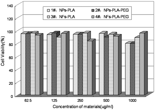
Cytotoxicity test is one of the most important indicators of the evaluation system for biomedical application. In this study, MTT test was applied to investigate the cytotoxicity of NPs and NFs on the viability of MSCs over 3 days. Owing to their ability of differentiation, MSCs cells were utilized to compare the biocompatibility of different NFs mats [Citation24] as well as nanoparticles. The cytotoxicity of various concentrations of the extract medium for the NPs and NFs fabricated from PLA or diblock copolymer mPEG-PLA are shown in Figure . It could be found that there was no obviously variety in cell viability when the MSCs were incubated with various concentrations of the extraction media of NPs and NFs.
Figure 2. In vitro cytotoxicity of NPs and NFs fabricated from PLA an PLA-PEG against MSCs cells at 72 h.
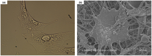
The toxicity of one material can also be detected by morphological changes of the cells that adhere on the surface of the material.[Citation25] Figure shows variations of MSCs cells when adhered to the NPs and NFs surface after 72 h of incubation. For NPs, the adhered cells formed monolayer areas of well spread cells (Figure (a)). With respect to the NFs, SEM observations revealed that cells on the NFs mats (Figure (b)) present a high level of cell/scaffold interaction, as demonstrated by the numerous pseudopodia and cell secretion emerging from the cells. Generally speaking, a DDS must be able to promote the normal cellular state, therefore, in the present study, the observed relatively nontoxic of NPs and NFs confirmed the understanding that the NPs and NFs matrix as well as the involved drugs and other components were pharmacological acceptability.
3.3. Protein release characteristics of NPs and NFs
According to the Bradford method,[Citation16] the dye-bind-BSA has a UV absorbance peak existed at 595 nm. Then, the release profiles of BSA from the NPs and NFs were calculated by UV spectroscopy based on a pre-determined calibration curve C = 0.0301A + 0.0011 (R2 = 0.9994) where C is the concentration of BSA (mg/ml) and A is its absorbance (linear range: 5–200 ug/ml).
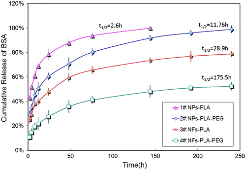
It has been suggested that drug release behaviors were invariably determined by the morphology of the matrix and particularly by the interactions between drug and matrix. The comparison of the in vitro release profiles of BSA from NPs and NFs is presented in Figure and Table . BSA-loaded NPs, fabricated by either PLA or mPEG-PLA generally showed an initial burst release at the first 2 h of release, with 48.7 ± 2.7% and 35.5 ± 3.4%, respectively. The core/sheath NFs, in which the drug is restricted into the inner layer, was expected to present a tempered low dose of release profiles, and during the initial stage, the released drug amount was limited at 25.3 ± 3.1% (for PLA NFs) and 10.5 ± 2.5% (for mPEG-PLA NFs), separately. From the perspective of drug release kinetics, the time taken to release 50% of drug (t1/2) was also different with the variation of the structure even with the same drug-loading matrix (Table ).
Table 2. BSA release profiles from NPs and NFs fabricated by PLA and mPEG-PLA.
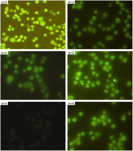
To gain more information about the influence of the categories of the encapsulation matrix on the release behavior of the drug, MPMs were incubated with the collected released mediums for mPEG-PLA NPs and NFs at the predetermined time intervals (24, 48 and 72 h) at 37 °C for 30 min, followed by fluorescence microscope analysis. In accordance with the release profiles of BSA from mPEG-PLA NPs (Figure ), the cell bound fluorescence intensity decreased by time, especially at 72 h of release period of time, the very weak fluorescence was detected in the medium (Figure (a)). On the contrary, the fluorescence signal of FITC-BSA released from mPEG-PLA NFs was increased notedly, as shown in Figure (b). It is suggested that [Citation26] the higher concentration of FITC-BSA, the larger the cell associated or internalization amount, resulting in the more fluorescence intensity and the brighter of the field of view. Therefore, these results pointed to the inevitably burst release of NPs and the effectively sustained release of NFs.
Figure 5. Microphotographs of the released FITC-BSA from mPEG-PLA NPs and NFs uptake by mouse peritoneal macrophages in terms of the fluorescence microscopic images. All the samples were collected from the release mediums at the indicated time intervals post-release (①24, ②48 and ③72 h) and exposured with the MPM for 30 min. The phagocytized cells were observed using the fluorescence microscope. (a) Cells incubated with mPEG-PLA NPs and (b) cells incubated with mPEG-PLA NFs.
3.4. Discussion
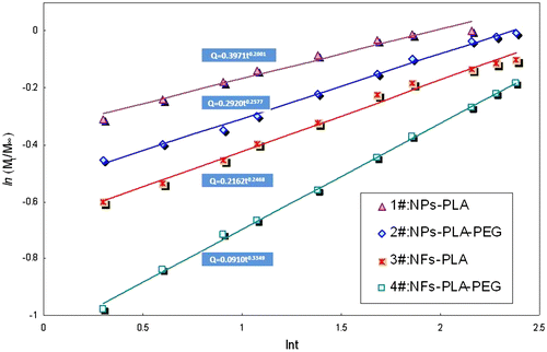
The BSA release profiles, in this study, could be analyzed and described according to the Peppas equation:(2)
where Mt is the mass of drug release at time t, M∞ is the total amount of drug encapsulated, t is the release time, k is a constant characteristic representing the structural and geometric of drug-polymer system, and n is the release exponent, which is representative the drug diffusion mechanism. From the slope and intercept of the plot (Figure ) of ln(Mt/M∞) vs. ln(t) for release of BSA from NPs and NFs fabricated by PLA and mPEG-PLA, the diffusion exponent n and the constant k were calculated as listed in Table . These are typical Fickian diffusion mechanism indicated by a series value of the release exponent n lower than 0.45, which means that drug diffusion is the primary factor in drug release.
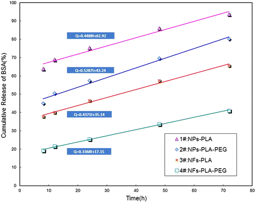
Furthermore, according to the zero-release equation from 8 to 72 h presented in Table and Figure , mPEG-PLA NFs exhibited the most linear drug release profile than other samples, as demonstrated by the highest correlation coefficient (R2 = 0.9974). Thus, from the release equation listed in Table , it can be concluded that the NFs fabricated by coaxial electrospinning process (3# and 4#) were able to provide a better sustained release behavior than those by emulsification process (1# and 2#). On the other hand, from the prospective of PEGylation, the introduction of PEG block (2# and 4#) could stabilize the drug diffusion rate, leading to release in a more sustained and smoother manner than those of PLA NPs and NFs.
Figure 7. Plots and curve fittings of cumulative release amount vs. time for dynamic BSA release from NPs and NFs. The release time is from 8 to 72 h.
It is suggested that the location of drug in DDS has a strongly site-specificity.[Citation27] therefore, to clarify the release mechanism of drug from the NPs and NFs, it is important to know where the drugs settle down within the delivery system. Generally, the hydrophobic drugs usually disperse inside the delivery systems, whereas, the hydrophilic ones are prone to site on the surface of the delivery system.[Citation28] Thus, in this study, BSA, the model drug, as a kind of hydrophilic protein, was supposed to enrich on the surface of the NPs and NFs, leading to a burst release at the first 2 h inevitably (Table ). On the other hand, it is suggested that the release procedure of water-soluble drugs from a polymeric matrix is followed by several steps: [Citation29] the hydrone from the medium diffuses into the inner of microencapsulation and dissolves the drug molecules, followed by immigration out of the matrix and back into the medium. Therefore, for the PLA NPs, the drug release mechanism could be presumed to follow these two parallel routes, as demonstrated in Figure (a).
Figure 8. The drug release mechanism for each drug delivery system. In total, the release procedures involves two major routes: (1) hydrone diffusion along the porous channels created during the encapsulation process → drug dissolve in the water → hydrone-bind drug immigration out → back to the medium; (2) burst release of drug evolved and absorbed into the macromolecules chains on the delivery surface during fabrications. Based on these release routes, the four samples showed different drug release profiles.
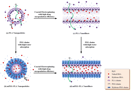
Owing to the different contact angles between these four samples, as listed in Table , it could be presumed that the surface conformations on the surface would be different too. As previous work reported,[Citation13] the PEG chains on the mPEG-PLA NPs exhibited a flexibility and mobility manner in terms of PEG moiety of anchoring to both the polyester core and extend out into the aqueous medium. Meanwhile, comparing to the hydrophobic surface of PLA NPs, the PEG chains grafted in mPEG-PLA NPs possess a lower contact angle (25.3 ± 2.6°), resulting in a higher degree of swelling. Hence, the surface conformation of mPEG-PLA NPs would be hypothesized like a mushroom (Figure (b)), and the swollen PEG chains would baffle the BSA molecules diffusion to the medium, which representing a lower burst release amount with a better sustained release profile.
From the perspective of NFs, coaxial electrospinning is an advanced technique to fabricate a core/sheath structure composite drug delivery system to protect active drug/protein from destruction and control the drug release all at once or moderately and even gradually. This stable core/sheath structure of NFs was expected to encapsulate BSA in a high encapsulation efficiency; hence, with respect of PLA NFs, even though the hydrophobic surface of PLA and hydrophilic core drug of BSA allowed easy penetration of water molecules into and easy diffusion of BSA-bind-hydrone out of the NFs sheath, the release profile was more moderately than those of both NPs samples (Figure (c)).
Furthermore, in a comparison of drug release behavior between PLA and mPEG-PLA NFs, the latter released a much lower concentration of BSA during the whole process. This could be also attributed to the introduction of hydrophilic PEG chains, as demonstrated in Figure (d), suggesting that the present of PEG chains allowed easier water adsorption than that of pure PLA NFs; and the swollen PEG chains occupied the whole surface of the NFs and avoided the hydrone molecules running into the inner of NFs and binding with drug followed by diffusion out to the medium. Therefore, the collected mPEG-PLA NFs provided a gradually release behavior of drugs.
4. Conclusion
Drug-loaded core/sheath composite NPs and NFs, in which BSA the model drug encapsulated in PLA or mPEG-PLA layer, were successfully fabricated through emulsification and coaxial electrospinning. With the optimized fabrication procedures, the obtain NPs and NFs had the small average diameters and narrow size distribution with uniform structure and smooth surface morphologies. The comparison between the surface charges of these NPs and NFs demonstrated that the electrospinning progress enriched a lot of positive charges to neutralize the negative charges of the PLA matrix. However, these two drug delivery systems were both safe to cells resulting from the in vitro cell adhesion and proliferation over 3 days.
The influences of the fabrication method and the sheath materials categories have been further considered. A larger amount of BSA was released from NPs than that from NFs at the first 2 h of release time, indicating the higher degree of drug adsorption on the surface of the NPs during the encapsulation process. During the coaxial electrospinning procedure, with encapsulating the more drug into the sheath than emulsification method did, the mPEG-PLA NFs, providing a more sustained drug release profiles over 10 days via a Fickian diffusion mechanism, offered zero-order drug release profiles with the highest correlation coefficient owing to its hydrophilicity chains of PEG. Based on the mechanisms of drug release, it is clear that the core-sheath drug delivery system with mPEG-PLA as the matrix fabricated via coaxial electrospinning is safe and significant to load and deliver drugs.
Disclosure statement
No potential conflict of interest was reported by the authors.
Additional information
Funding
References
- Tomoko I, Burnett JC Jr. Protein therapeutics for cardiovascular disease: It is all about delivery. J. Am. College Cardiology. 2012;60:2558–2560.
- Rosalinda M, Raffaele DC. Stem cells and growth factor delivery systems for cardiovascular disease. J. Biotechnol. 2011;154:291–297.
- Zhirong Z, Gongtie L, Tsuneji N, Shixiang H. Mitoxantrone polybutyl cyanoacrylate nanoparticles as an anti-neoplastic targeting drug delivery system. Int. J. Pharm. 1996;139:1–8.
- Chenlu L, Yanna C, Lin Z, Pierce KHC, Chi-Hwa W. Development of a gene/drug dual delivery system for brain tumor therapy: potent inhibition via RNA interference and synergistic effects. Biomaterials. 2013;34:7483–7494.
- Diana C, Artur JM, Valente M, Graça M, João Q. Plasmid DNA microgels for drug/gene co-delivery: a promising approach for cancer therapy. Colloid Surf., A. 2014;442:181–190.
- Fredy M, Gursel A, Weihua L. A review of drug delivery systems for capsule endoscopy. Adv. Drug Delivery Rev. 2014;71:77–85. doi.10.1016/j.addr.2013.12.007
- Lam PL, Gambari, R. Advanced progress of microencapsulation technologies: in vivo and in vitro models for studying oral and transdermal drug deliveries. J. Controlled Release. 2014;178:25–45.
- Chuanyun D, Bochu W, Hongwei Z. Microencapsulation peptide and protein drugs delivery system. J. Controlled Release. 2014;178:25–45.
- Isabel MM, Maria FB, Manuel C, Alírio ER. Microencapsulation of essential oils with biodegradable polymeric carriers for cosmetic applications. Chem. Eng. J. 2014;245:191–200.
- Jian Z, ChangSheng L, Yuan Y, et al. Preparation of hemoglobin-loaded nano-sized particles with porous structure as oxygen carriers. Biomaterials. 2007;28:1414–1422.
- Xiaoqian S, Yuan Y, Changsheng L, Xinyi T, Yan S, Feng X. Influence of PEG chain on the complement activation suppression and longevity in vivo prolongation of the PCL biomedical nanoparticles. Biomed. Microdevices. 2009;11:1187–1194.
- Carla S, Carla J, Silva ZB, et al. Preparation and characterization of polysaccharides/PVA blendnanofibrous membranes by electrospinning method. Carbohydr. Polym. 2014;99:584–592.
- Thuy TTN, Chiranjit G, Seong-Gu H, Noppavan C, Jun SP. Porous core/sheath composite nanofibers fabricated by coaxial electrospinning as a potential mat for drug release system. Int. J. Pharm. 2012;439:296–306.
- Ning H, Jed J, John JL, Jessica OW. Hydrogel- electrospun fiber composite materials for hydrophilic protein release. J. Control Release. 2012;158:165–170.
- Tatsuya O, Kengo T, Satoru K. Time-programmed dual release formulation by multilayered drug-loaded nanofiber meshes. J. Control Release. 2010;143:258–264.
- Xiaoqian S, Yuan Y, Changsheng L, Feng X, Yan S. Comparison of the PLA-mPEG and mPEG-PLA-mPEG copolymers nanoparticles on the plasma protein adsorption and in vivo biodistribution. Soft Matter. 2009;5:2875–2883.
- Wei J, Fang Y, Jeroen JJP, et al. Fibrous scaffolds loaded with protein prepared by blend or coaxial electrospinning. Acta Biomater. 2010;6:4199–4207.
- Jing H, Jianfeng Z Ruixue Y, Guiping M, Dongzhi Y, Jun N. Electrospinning of methoxy poly(ethylene glycol)-grafted chitosan and poly(ethylene oxide) blend aqueous solution. Carbohydr. Polym. 2011;83:270–276.
- Bradford MM. A rapid and sensitive method for the quantitation of microgram quantities of protein utilizing the principle of protein-dye binding. Anal. Biochem. 1976;72:248–254.10.1016/0003-2697(76)90527-3
- Qiang W, Wei W, Bo L, et al. Uniform-sized PLA nanoparticles: preparation by premix membrane emulsification. Int. J. Pharm. 2008;359:294–297.
- Vanessa CFM, Philippe L, Annette G, et al. Relationship between complement activation, cellular uptake and surface physicochemical aspects of novel PEG-modified nanocapsules. Biomaterials. 2001;22:2967–2979.
- Nagihan O, Pınar T, Filiz A. Affecting parameters on electrospinning process and characterization of electrospun gelatin nanofibers. Food Hydrocolloid. 2014;39:19–26.
- Natthan C, Praneet O, Theerasak R, Tanasait N, Pitt S. Preparation and characterization of chitosan- hydroxybenzotriazole/polyvinyl alcohol blend nanofibers by the electrospinning technique. Carbohydr. Polym. 2010;81:675–680.
- Bronwin LD, Cédryck V, Firas R, Justin JCW, Julie HC, Andrew KW. Electrospinning and crosslinking of low-molecular-weight poly(trimethylene carbonate-co-l-lactide) as an elastomeric scaffold for vascular engineering. Acta Biomater. 2013;9:6885–6897.
- Rayna B, Nelly G, Tonya A, Rumiana T. Cell adhesive behavior of PVA-based hybrid materials with silver nanoparticles. Surf. Coat. Technol. 2013;235:186–191.
- Franz G, Andrea S, Michael W. Lectin-mediated drug delivery: binding and uptake of BSA-WGA conjugates using the Caco-2 model. Int. J. Pharm. 2002;237:227–239.
- Ruiling i, Rui G, Fuyin Z, Hui L, Jianyong Y, Xiangyang S Controlled release and antibacterial activity of antibiotic-loadedelectrospun halloysite/poly(lactic-co-glycolic acid) composite nanofibers. Colloid Surf., B. 2013;110:148–155.
- Sascha M, Andreas G, Thomas K. Electrospun biodegradable nanofiber nonwovens for controlled release of proteins. J. Control Release. 2008;127:180–187.
- Fredenberg S, Wahlgren M, Reslow M, Axelsson A. The mechanisms of drug release in poly(lactic-co-glycolic acid)-based drug delivery systems – a review. Int. J. Pharm. 2011;415:34–52.10.1016/j.ijpharm.2011.05.049

