Abstract
Accumulations of sanitary textile materials often lead to clogging of pumps in the wastewater system. Simulation of clogging phenomena may help to identify means of reducing the risk of clogging. In order to provide realistic initial conditions for clogging simulations, this study characterises textiles in artificial wastewater in the suction pipe to a dry-installed pump at nine different operating points. The textiles are recorded approximately 3.5 pipe diameters from the pump inlet and approximately three pipe diameters from the suction pipe bend at pipe Reynolds numbers in the range 300,000–900,000. Parameters of position, orientation, elongation and projected two-dimensional (2D) area are extracted using image analysis. The resulting parameters from the different operating points are compared using analysis of variance. The results show that the position, orientation and elongation do not change significantly with the operating point, while the projected 2D area decreases with an increased flow.
Keywords:
Introduction
Extensive sewer networks of channels, pressure pipes and pumping stations, transporting wastewater from e.g. sinks, washing machines and toilets to wastewater treatment plants, are crucial for modern metropolises. However, the reliable operation of the sewer system is challenged by a high content of sanitary refuse, commonly entering the sewer system through toilets. Due to the lack of significant degradation of these solids, they tend to accumulate, causing risk of blockages in drainage and clogging in wastewater pumps. Therefore, a very important parameter in the development of new wastewater pump designs is their ability to handle these objects without clogging. The resistance to clogging is currently tested experimentally. However, the industry is moving towards simulation driven development, which requires the ability to simulate clogging phenomena. One of the first steps to accomplish this complex simulation is to establish how to represent the sanitary refuse based on the composition of wastewater and to determine valid initial conditions for the sanitary objects.
The composition of solids in wastewater has been investigated by various authors during the last several decades, using questionnaires about refuse habits and analysing samples of wastewater (Friedler, Brown, and Butler Citation1996; Niessen and Chansky Citation1970). Recently, Spence et al. (Citation2016) presented the daily variations of different sanitary items in three different catchment areas and found that the most common sanitary item in the wastewater in the investigated areas was wet wipes. Mitchell et al. (Citation2017) also investigated the content of wastewater based on samples and found that textiles constituted around 33% of the samples. These studies indicate that wet wipes constitute a significant amount of the solids content in wastewater.
The motion of textile material, like wet wipes, has been studied in partially filled pipe networks in order to understand the impact of decreasing the flush volume of toilets. Littlewood and Butler (Citation2003) investigated the movement mechanisms and behaviour of gross solids in small pipes with intermittent flow, as the solids are transported by toilet flushing. They identified three mechanisms of movement, the solid moving down the pipe only during a flush, the solid sliding down the pipe with water building up behind the solid, and a combination of the two. Similarly, McDougall and Wakelin (Citation2007) and Walski et al. (Citation2011) investigated transport of large deformable solids and also identified three movement mechanisms. Common for the investigations is the focus on the velocity of the solids compared to the velocity of the fluid as well as on the solid transport distance. These properties, along with knowledge of the amount of flushed material, are important in the development of models of the pollutant storage rates and models of solid transport in sewers. Unlike the mentioned studies, the present work analyses the sanitary material directly upstream of a wastewater pump.
Wastewater pumps are either submersible or dry-installed. The water inflow depends on the type of pump installation since the wastewater enters a dry-installed pump through a suction pipe, while it enters submersible pumps directly from the pump sump. The present work characterises a standard piece of non-woven textile in the suction pipe upstream of a dry-installed pump through parameters as textile area m00, Y position of the centroid, the orientation θ and an elongation ratio ε. Furthermore, the influence of the pump operating point on these parameters is investigated, since the type of clogging in the pump has proven to depend on the operating point (Thamsen Citation2009). This analysis has an aim to determinate appropriate initial conditions for textiles in clogging simulations.
Experimental approach
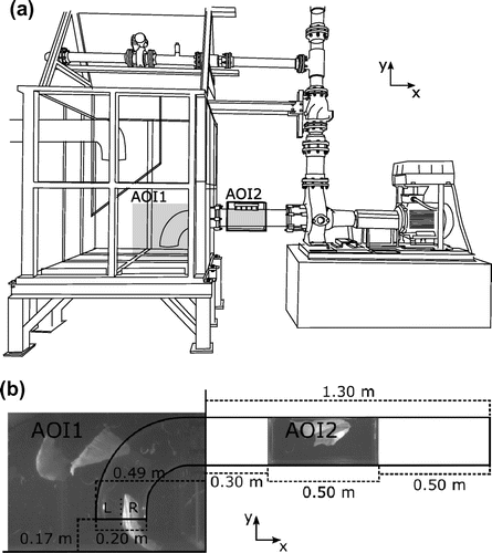
A scaled pumping station (1:3) with a dry-installed pump is located in the Department of Fluid System Dynamics in TU Berlin. The test rig is sketched in Figure (a) and includes a pump sump and a suction pipe in acrylic glass, which enables recording of the textile in these areas. Two areas of interest are marked with grey in Figure (a) and illustrated in more detail in Figure (b). The first area of interest (AOI1) is in the pump sump at the inlet to the suction pipe. The second area of interest (AOI2) is covering 0.5 m of the horizontal part of the suction pipe 0.5 m upstream of the inlet to the pump. A box of acrylic glass of size 0.50 m × 0.36 m × 0.32 m was fixed around the circular suction pipe at AOI2. The box is filled with water to decrease the distortion of light through the circular surface of the pipe. Using the box, the distortion of light is negligible. The water in the system is pumped from the pump sump to a smaller tank from where it flows back into the pump sump. A plate is placed in the pump sump as sketched in Figure (a), to decrease the amount of air-bubbles appearing in the images. Two cameras recording AOI1 and AOI2 were synchronized and images taken at the same time were given the same name. This means that the connection between the motion of the pieces of textile in the suction sump and inside the suction pipe can be analysed. The cameras used for recording AOI1 and AOI2 were Basler acA1300–30um (1.3 MP) and Basler acA1920–155um (2.3 MP), respectively. AOI1 covers 850 mm × 635 mm and was recorded with a framerate of 30 fps. AOI2 covers 520 mm × 225 mm and was recorded with a frame rate of 150 fps.
Figure 1. (a) Sketch of the scaled pumping station with a dry installed pump. The grey areas mark the two areas of interest, AOI1 and AOI2. (b) Simplified sketch of the suction pipe. AOI1 and AOI2 are the two areas of interest. L and R mark the left and the right part of the suction pipe.
The tests were done at three different impeller speeds and at the best efficiency point (100% BEP), part load (75% BEP), and heavy part load (50% BEP) for each impeller speed. This results in tests at the nine different operating points listed in Table . Volume flows, Qf, in the range of 170 to 512 m3/h, led to Reynolds numbers in the order of 300,000 to 900,000 based on the inner diameter of the suction pipe. The velocity of the fluid vf was in the range from 1.50 to 4.53 m/s based on volume flow and suction pipe cross-sectional area. The velocity of the textile, vt, in the pipe was in the range 1.53 to 4.28 m/s. This range is found based on image analysis of the acquired images. It is seen that the velocities of the fluid and textile are very similar, which is expected due to very similar densities of the wet textile and the water.
Table 1. Volume flow, Qf flow velocity, vf, and textile velocity, vt. The velocity of the textile is based on image analysis of images from AOI2.
Because of hygienic issues, and to create better optical access, artificial wastewater is commonly used in clogging tests. The artificial wastewater is created using clean water with an addition of solids commonly found in wastewater. Due to large variations in the solids content in wastewater, caused by different habits of flushing refuse from country to country and from catchment area to catchment area as well as the influence of e.g. the weather and the network operation, there is no clear general characterisation of the solids composition in wastewater. However, a definition of standard wastewater would ease the evaluation of the ability of wastewater pumps to handle solids in wastewater. Thamsen (Citation2009) used Aro super dust cloths made for household cleaning, which are similar to the wet wipes found in wastewater, to create artificial wastewater and evaluate how the type of clogging depends on the pump operating point. The same type of dust cloths has since been used in several experimental investigations in TU Berlin as a part of a work to define a test standard for wastewater pumps (Pöhler et al. Citation2015). In the present experiments the artificial wastewater is created using clean water and 20 of the mentioned dust cloths. These are commercially available and the properties are specified in Table . The dust cloths have proven to recreate the different types of clogging caused by real wastewater (Thamsen Citation2009). The dust cloths were left in water for 24 hours before each test to ensure they were fully soaked with water.
Table 2. Characteristics of the dust cloth used to create artificial wastewater.
Using only 20 dust cloths in each test, allows the dust cloths to be observed one at the time and limits the changes in operating point due to accumulation of the dust cloths inside the pump. The tests are run until the visual appearance of the dust cloths becomes worn or until all dust cloths have accumulated inside the pump, meaning that no more dust cloths are being circulated back to the pump sump to be recorded again. The tests are repeated 5–8 times per operating point to achieve a satisfactory amount of data, resulting in an average of 236 dust cloths per operating point. In total 60 separate tests were made and a total of 2123 dust cloths were recorded as they passed through the suction pipe. The final data-set consisted of more than three million pictures with and without dust cloths.
Image processing
The acquired images are processed using an in-house code in MATLAB developed for the purpose. The code identifies the pictures containing dust cloths and determines the parameters needed for the analysis. These parameters are sketched in Figure and are the textile area m00, vertical position Y, elongation ratio ε, and orientation θ.
Figure 2. Sketch of the parameters analyses in the images. The ellipse has the same second-order moment as the blob formed by the dust cloth.
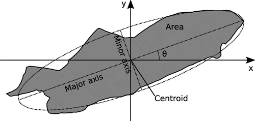
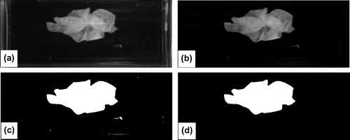
Figure shows three main steps of the image processing. Figure (a) is an example of an original image from AOI2. Figure (b) shows this image after the average background has been subtracted. Since the lighting in the test hall changed during the day, the average background was identified for each of the 60 tests. After background subtraction the grey scale image is converted to a binary image using a threshold value. An appropriate threshold value ensures that the pixels representing the dust cloth are converted to one and the value of the pixels representing the background is converted to zero. The resulting binary image is presented in Figure (c). As seen in Figure (c), the image contains small areas with white pixels as well as the big blob, representing the dust cloth. The small areas can be small pieces of textiles, air bubbles or reflections on the surface of the pipe. These are removed with a size filter, deleting all objects with a size smaller than 20,000 pixels. The final image is presented in Figure (d). The described steps apply to images from both AOI1 and AOI2.
Figure 3. Overview of image processing steps. (a) Original image, (b) background subtraction, (c) conversion to binary image using an intensity threshold value, (d) small objects removed using a size filter.
Subsequently, the images containing dust cloths are identified and the moments of the remaining blobs, representing the dust cloths, can be determined based on Equation (Equation1(1) ), where axy denotes the pixel brightness with a number of zero (black) or one (white) for binary images and x and y are pixel coordinates. For binary images the zeroth order moment is also the area of the blob.
(1)
Based on the first- and zeroth-order moments the coordinates of the centroid, X and Y can be determined using Equation (Equation2(2) ).
(2)
The shape of the dust cloths is described through an elongation ratio ε, which is defined as the ratio between the length of the major axis and the minor axis of the ellipse with the same second-order moment as the blob, as given in Equation (Equation3(3) ), where lma is the major axis length and lmi is the minor axis length.
(3)
The orientation of the dust cloths is found as the angle between the x-axis and the major axis of the ellipse with the same second-order moment as the dust cloth.
Results
The properties of area, elongation ratio, orientation and vertical position of the dust cloths in the suction pipe have been captured for all operating points. The analysis of variance (ANOVA) is used to test if the mean value of these properties changes with the operating point. The hypothesis H0 that all the means, μ, are equal, given in Equation (Equation4(5) ) is tested. The results are displayed in Table .
(4)
Table 3. Comparison of the mean values from each operating point using ANOVA gives the p-values listed in the table. A p-value less than 0.05 indicates that the difference between the mean values is significant.
(5)
The p-value is the probability for the same or more extreme results to occur if the hypothesis H0 is true. Therefore, if p < 0.05 it is concluded that H0 is false and that there is significant difference between the obtained mean values, meaning that the operating point influences the tested parameter.
As seen in Table the p-value reveals that the area of the dust cloths changes significantly with the operating point. The mean area as a function of the volume flow in the pipe is presented in Figure with 95% confidence intervals. It is seen in Figure , that there is a decrease in the area with an increase of the flow. Oppositely, Table shows that the elongation ratio, orientation and vertical position do not change significantly with the operating point.
Figure 4. Area as function of flow velocity in the suction pipe. The bars show the 95% confidence intervals. × 800 RPM, ο 985 RPM, ∆ 1200 RPM.
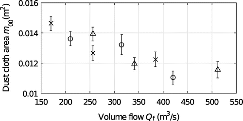
Figure (a) shows the distribution of the centroid of the dust cloths over a vertical section of the suction pipe, where Y = 0 represents the centre of the pipe. It is seen that the dust cloths mainly move around 0.02 m below the centre of the pipe.
Figure 5. (a) The distribution of dust cloths over a vertical section of the suction pipe. (b) Mean dust cloth area as a function of the vertical position in the pipe. (c) Mean ratio of the major and minor axis. (d) Mean orientation as function of the vertical position. The error bars mark the 95% confidence intervals. Y = 0 in the centre of the pipe.
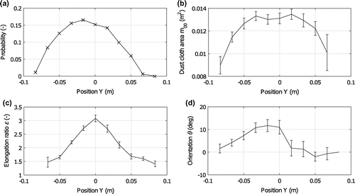
The dust cloth area m00, orientation θ and elongation ratio ε, depend on the vertical position in the pipe. This is illustrated in Figure (b–d). The mean area of the dust cloths as a function of the vertical position of the centroid of the dust cloths in the pipe is presented in Figure (b) with 95% confidence intervals. It is seen that the area is nearly constant in the range from –0.05 m to 0.05 m, and that it decreases significantly outside this range.
Figure (c) shows the mean elongation ratio ε as a function of the dust cloth position. It appears that the maximum ratio of around three, occurs in the centre of the pipe. The elongation ratio decreases to 1.5 at the outer part of the suction pipe.
The angle between the dust cloths and the X-axis (see θ in Figure ) as a function of the vertical position is presented in Figure (d). There is a clear change in the angle with the vertical position. Above the centre of the pipe the dust cloths are very close to parallel to the flow, while there is an angle of around 12° to the horizontal just below the centre of the pipe.
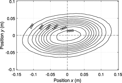
The contour plot presented in Figure is made by translating the centroid of all 2123 recorded dust cloths to a common position and noting the area they cover. The contour plot shows that the dust cloths cover a regularly shaped ellipse with a small angle to horizontal and an elongation ratio of approximately two.
Figure 6. Contour plot of the extent of the dust cloths, when they are all placed with the centroid in a common position.
Comparison between dust cloth positions in AOI1 and parameters in AOI2
Table shows a comparison of the dust cloth parameters in AOI2, depending on where the dust cloths enter the suction pipe. The inlet to the suction pipe is divided into a left and a right half of the pipe, marked with L and R in Figure (b). Table shows only minor differences between the dust cloth area and elongation ratio in AOI2. However, the Y position shows a tendency of the dust cloths entering in the left side of the inlet to the suction pipe to have a position above the centre of the pipe, while the dust cloths entering at the right side of the suction pipe show a tendency to be below the centre of the pipe. Furthermore, the angle to the X-axis is higher for dust cloths entering in the right side of the suction pipe. This observation corresponds to the results presented in Figure (d), showing that the angle is higher for dust cloths below the centre of the pipe.
Table 4. Dependence between AOI1 and AOI2.
Several additional parameters such as the textile size and properties, impeller type, and geometrical changes in the inlet pipe may affect the results and this could be investigated in detail in future studies using design of experiments to decide on which combinations of parameters should be tested. Furthermore, observation of the textile as it leaves the impeller to determine how the appearance of the textile changes as it is pumped is also an interesting perspective.
Conclusion
Based on images of 2123 dust cloths passing through the suction pipe to a dry-installed wastewater pump, the area, orientation, elongation ratio and vertical position of dust cloths upstream of the pump inlet have been analysed, and the dependency of these parameters on the operating point of the pump has been determined.
The most common dust cloth position is at 0.02 m below the centre of the suction pipe. At this position the values of area, elongation ratio and orientation are 0.013 m2, 3.1 and 12°, respectively. These parameters are slightly different than the mean value of each property and the variation of the properties along the span of a vertical section of the pipe, indicates that appropriate parameters should be found based on the desired vertical position of the simulated dust cloth rather than the overall mean values. The position of the dust cloths in AOI2 is connected to the position in AOI1 where the dust cloths enter the suction pipe. Dust cloths entering in the left part of the suction pipe tend to have a position above the centre of the pipe in AOI2, while dust cloths entering the right part of the suction pipe tend to have a position below the centre.
There is no significant change in the mean value of the orientation, elongation ratio and vertical position of the dust cloths between the operating points. The recorded area of the dust cloths in the suction pipe changes with the operating point and ranges from 0.011 to 0.015 m2. The higher the flow rate, the smaller the area. The insignificant change of the position, orientation and elongation ratio shows that a very similar textile shape can be used as initial condition for simulations at different operating points, while care must be taken regarding the covered area and thereby the degree of crumbling. Notice that the images are taken from one direction, meaning that a two-dimensional (2D) representation of the dust cloths is obtained rather than the full three-dimensional (3D) shape.
The determined parameters of orientation, area and elongation ratio as function of the position in the pipe will be implemented as initial conditions for textile in future clogging simulations. The independence of operating point for three out of four tested parameters shows that different types of clogging occurring at different operating points is likely due to a change in the flow conditions inside the pump rather than upstream of the pump. Simulations of clogging effects, using the determined initial conditions, may help to understand these different types of clogging and work as a tool in the design process of wastewater pumps to ensure a high resistance to clogging.
Disclosure statement
No potential conflict of interest was reported by the authors.
Acknowledgements
Financial support from Grundfos Holding A/S and Nordic Water Network is gratefully acknowledged.
References
- Friedler, E., D. Brown, and D. Butler. 1996. “A Study of WC Derived Sewer Solids.” Water Science and Technology 33: 17–24. doi:10.1016/0273-1223(96)00365-4.
- Littlewood, K., and D. Butler. 2003. “Movement Mechanisms of Gross Solids in Intermittent Flow.” Water Science and Technology 47: 45–50.
- McDougall, J., and R. Wakelin. 2007. “The Influence of Flush Volume and Branch Drain Cross-Section on Deformable Solid Transport in Attenuating Flows.” Building Services Engineering Research and Technology 28: 7–22.10.1177/0143624406070586
- Mitchell, R.-L., P. U. Thamsen, M. Gunkel, and J. Waschnewski. 2017. “Investigations into Wastewater Composition Focusing on Nonwoven Wet Wipes.” Technical Transactions 1: 125–135. doi:10.4467/2353737XCT.17.010.6107.
- Niessen, W., and S. Chansky. 1970. “The Nature of Refuse.” Proceedings of National Incinerator Conference, New York, ASME, 1-24.
- Pöhler, M., S. Gerlach, K. Höchel, T. Mengdehl, and P.U. Thamsen. 2015. Linking Efficiency to Functional Performance by a Pump Test Standard for Wastewater Pumps. Proceedings of ASME-JSME-KSME Joint Fluids Engineering Conference, July 26–31, Seoul. doi:10.1115/AJKFluids2015-33763
- Spence, K., C. Digman, D. Balmforth, J. Houldsworth, A. Saul, and J. Meadowcroft. 2016. “Gross Solids from Combined Sewers in Dry Weather and Storms, Elucidating Production, Storage and Social Factors.” Urban Water Journal 13: 773–789. doi:10.1080/1573062X.2015.1025081.
- Thamsen, P.U. 2009. “Cutting Clogging in Wastewater.” World Pumps April: 22–25. doi:10.1016/S0262-1762(09)70140-3
- Walski, T., J. Falco, M. McAloon, and B. Whitman. 2011. “Transport of Large Solids in Unsteady Flow in Sewers.” Urban Water Journal 8: 179–187. doi:10.1177/0143624406070586.
