Abstract
A liquid crystal (LC) device switchable between the reflective and transmissive modes without sub-pixel division is proposed. By using dye-doped nematic LCs for the top LC layer, transflective displays with high reflectance were realized. It is expected that the proposed device can be applied to high-reflectance transflective devices for outdoor applications.
1. Introduction
Liquid crystal displays (LCDs) have been widely used for various applications because of their low power consumption, light weight, and thinness. With the increasing demand for mobile devices, the need for high-quality displays that have high indoor and outdoor performances has increased of late. Transflective LCDs, in which each pixel is divided into two sub-pixels Citation1–9, have been introduced to meet these needs. One sub-pixel operates in the transmissive mode for indoor use, and the other operates in the reflective mode for outdoor use. The light efficiency of transflective LCDs is not high enough, however, because the division of each pixel into sub-pixels results in a low aperture ratio. Thus, LCDs with high performance in both indoor and outdoor environments without sub-pixel division are required.
To realize a transflective device without sub-pixel division, a reflective polarizer has been used instead of a half-mirror Citation10. A reflective polarizer has a reflection axis (RA) that is perpendicular to the transmission axis (TA). The device can reflect ambient light and can transmit backlight using the entire pixel area. However, it suffers from image inversion in which the dark state of the transmissive mode is the same as the bright state of the reflective mode.
To eliminate image inversion, several transflective devices that use the whole pixel area in both reflective and transmissive modes have been proposed Citation11 Citation12. In one of these devices, dual nematic liquid crystal (LC) layers were used together with a reflective polarizer. Although image inversion is eliminated in this device, an additional LC panel lowers the reflectance, and the parallax problem becomes serious due to the high thickness compared to the pixel dimension. Another device uses an electro-phoretic layer to realize a transflective device without sub-pixel division. This device, however, requires an applied voltage higher than 40 V to switch the electro-phoretic layer, and the aperture ratio in the transmissive mode is limited by the particles. The reflectance of the electro-phoretic layer is lower than 25%.
Recently, to overcome the parallax problem and to increase the reflectance, a structure in which a reflective polarizer is placed between two nematic LC layers Citation13 was proposed. Even though the reflectance of the reflective polarizer is high, the overall reflectance of the device might be limited by the top absorption polarizer. The reflectance is significantly reduced by the double pass through the top polarizer Citation14.
In this study, an LC device capable of using the entire pixel in both reflective and transmissive modes without sub-pixel division is proposed. By employing dye-doped LCs, the proposed device can obtain higher reflectance than in the previously proposed modes because a polarizer-free LCD can be achieved. We expect that the proposed device can be applied to realize high-reflectance transflective devices for outdoor applications.
2. Configuration and operational principle
To realize a transflective LC device without sub-pixel division, a reflective polarizer and dichroic dyes can be used. In this device, the dichroism of dichroic dyes that have two different absorption coefficients, and
,
is used. is the absorption coefficient for polarization parallel to the principal molecular axis of the dye molecules and
is the absorption coefficient for polarization perpendicular to the principal molecular axis of the dye molecules. When the dyes are aligned in the LCs, they absorb the incident light that is polarized parallel to the principal molecular axis and transmit the perpendicularly polarized light. Using the Beer–Lambert law Citation15 under the condition of a dilute solution, the normalized transmittance of a homogeneous dye-doped LC (DDLC) cell can be given by
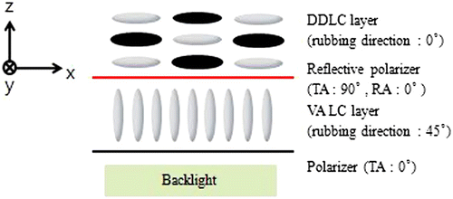
shows the configuration of the proposed LC device that is switchable between reflective and transmissive modes. It consists of a polarizer, a nematic LC layer, a reflective polarizer, and a DDLC layer, in that order. A vertically aligned (VA) nematic LC layer is placed between the bottom polarizer (TA: 0°) and the reflective polarizer (TA: 90°, RA: 0°) for normally black operation in the transmissive mode. A DDLC layer is placed on top of the reflective polarizer for the reflective mode. The DDLC layer is operated only for the reflective mode, while the VA layer is operated only for the transmissive mode. The proposed LC device is switchable between reflective and transmissive modes without image inversion by using the dichroism of the dichroic dyes. The DDLC layer is homogeneously aligned parallel to the RA of the reflective polarizer so that ambient light is absorbed. In the transmissive mode, the light transmitted through the reflective polarizer passes through the DDLC layer. On the other hand, in the reflective mode, ambient light and the light reflected by the reflective polarizer are absorbed by the DDLC layer. As the transmissive mode operates in the dark state of the reflective mode, image inversion is removed.
To explain the operation of the proposed device shown in , the light propagation paths corresponding to each layer are shown in . In the reflective mode, the DDLC layer acts as an active absorber, and the reflective polarizer (TA: 90°, RA: 0°) acts as a reflector that reflects only 0° linearly polarized light and transmits 90° linearly polarized light. The VA layer maintains its initial vertical alignment for operation in the reflective mode. When the DDLCs are initially homogeneously aligned along the RA, the light polarized along the RA is absorbed by the dichroic dyes. Thus, the dark state of the reflective mode can be obtained as shown in . For the bright state, an electric field is applied to the DDLC layer so that it becomes VA. Then, ambient light passes through the DDLC layer without absorption and phase retardation. Incident light is reflected by the reflective polarizer so that the bright state is obtained, as shown in .
Figure 2. Operation of the proposed transflective LCD. (a) Dark and (b) bright states of the reflective mode. (c) Dark and (d) bright states of the transmissive mode.
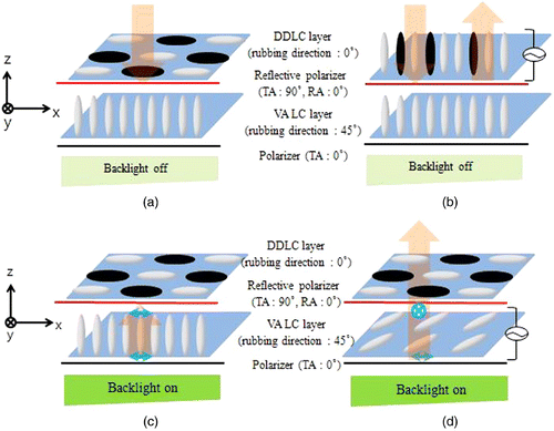
For the operation of the proposed device in the transmissive mode, the DDLC layer remains at the initial homogeneous alignment state to absorb ambient light. The light incident from the backlight system becomes 0° linearly polarized light when passing through the bottom polarizer (TA: 0°). There is no change in polarization while passing through the VA layer. Finally, the polarization is perpendicular to the TA of the reflective polarizer (TA: 90°, RA: 0°) so that the dark state is obtained, as shown in . For the bright state of the transmissive mode, an electric field is applied to the VA layer so that the layer acts as a half-wave plate. Then, the 0° linearly polarized light transmitted through the bottom polarizer is rotated to 90° linearly polarized light while passing through the VA layer. As a result, it passes through the reflective polarizer and the DDLC layer with 90° linearly polarized light since the polarization is perpendicular to the principal molecular axis of the dye molecules. The bright state in the transmissive mode can be obtained as shown in . Thus, the whole pixel area can be operated in both reflective and transmissive modes without sub-pixel division. As ambient light is absorbed by the DDLC layer when the transmissive mode is in the dark state, the proposed device has no image inversion.
3. Experimental results
A DDLC cell and a VA cell were fabricated to confirm the operation of the reflective and transmissive modes. For the DDLC cell, a homogeneous alignment polyimide (H-PI) (PIA-5310-GS10, Chisso) was spin-coated onto the top and bottom indium-tin-oxide glass substrates, followed by a baking process to polyimidize the H-PI. Then, the cells were assembled with the cell gap fixed at 11 μm using silica spacers. To prepare dye-doped LCs, nematic LCs (MLC-0223, Merck, ) were mixed with dichroic dyes at 95:5 wt%. As dichroic dyes have an inherent absorption wavelength, four different dyes (AB3, AG1, AR1, and AC1, Nematel) were mixed, with 8:5:12:4 composition to obtain a black color that absorbs broad wavelengths. The DDLC mixtures were injected into the empty cells. For the VA cell, a vertical-alignment polyimide (V-PI) (AL-60101, Nissan Chemical) was spin-coated onto the top and bottom indium-tin-oxide glass substrates, followed by a baking process for the polyimidization of V-PI. Then, the cells were assembled with the cell gap fixed at 4 μ m using silica spacers. The negative LCs (MLC-6608, Merck, ≥n=0.083,
) were injected into the empty cells.
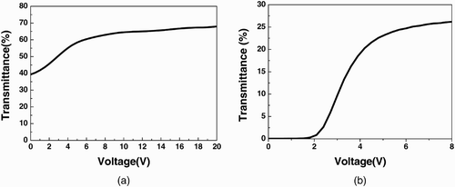
To confirm the electro-optic characteristics of the fabricated cells, the voltage–transmittance (V–T) curve of the DDLC and VA cells was measured. shows the V–T curve of the DDLC cell that was measured using a polarizer. The rubbing direction of the DDLC cell was set parallel to the TA of the polarizer. Then, an initially dark state was observed using homogeneously aligned dichroic dyes that absorbed the light transmitted through the polarizer. When an electric field was applied to the DDLC cell, the LCs and dye molecules were reoriented along the direction of the electric field. The maximum transmittance was obtained at 15 V. It is expected that the initial dark state can be improved by controlling the cell gap, changing the concentration of the dyes, and using dyes with higher DRs.
The measured V–T curve of the VA cell between the crossed polarizers is shown in . A superior dark state was initially observed. The maximum transmittance was obtained at an applied voltage of 6 V. Although the VA cell was used for the LC layer in this work, other normally black LC modes with half-wave phase retardation can be used for the proposed device.
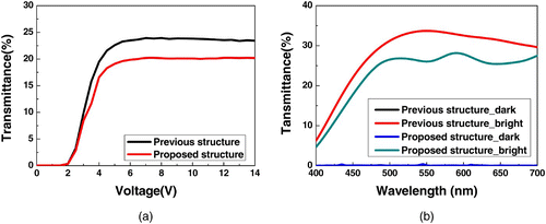
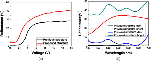
The proposed structure was compared with the previous structure in which DDLCs were not used Citation13. The previous structure consists of the bottom (reflective) polarizer, the bottom LC layer, the middle polarizer, the top LC layer, and the top polarizer in that order. The top and bottom LC layers are used for gray-level control and mode switching, respectively. The measured V-T curves of the fabricated devices in the transmissive mode are shown in . In the transmissive mode, only the bottom LC layer is used in both structures wherein the saturation voltage was the same, but the maximum transmittance was different. This is because the light transmitted through the reflective polarizer in the proposed structure was absorbed by the dyes. shows the transmission spectra of the proposed device measured using a spectrometer (MCPD-3000, Photal). An identical VA cell was used in both devices so that the same voltage could be applied for the bright state. The spectrum of the dark state was the same in both structures, but the bright state spectra were different due to the absorption by the dyes. The transmittance of the proposed structure can be improved by using dichroic dyes with a smaller and a higher DR, although it was lower than that of the previous structure in the bright state. shows the voltage–reflectance (V–R) curves and reflection spectra of the proposed device compared to the previous device. The previous structure was operated using the retardation of the LCs between the crossed polarizers, whereas the proposed device is operated by the dichroism and the reorientation property of the dyes. The reflectance of the previous device was 0.74% in the dark state and 28.69% in the bright state, whereas the reflectance of the proposed device was 3.71% in the dark state and 40.87% in the bright state. The reflectance of the previous structure was limited by the top polarizer and the wavelength-dependent phase retardation, as shown in . Only the value of
of the dye, however, can limit the reflectance of the device in the proposed structure. Although the dark state of the previous device is superior to that of the proposed device, the bright state of the proposed device is much better. Moreover, the dark state of a DDLC cell can be improved by controlling the cell gap and the wt% of the dye, and by using the polymer networked structure.
4. Conclusion
An LC device that is switchable between reflective and transmissive modes was proposed. Using a DDLC layer, the top polarizer was removed to improve the reflectance of the reflective mode. It is expected that high brightness can be achieved in both transmissive and reflective modes by using dyes with a smaller and a higher DR.
Acknowledgements
This work was supported by Mid-career Researcher Program through NRF grant funded by the MEST (No. 2010-0000334).
References
- Lee , S. H. , Do , H. W. , Lee , G.-D. , Yoon , T.-H. and Kim , J. C. 2003 . Jpn. J. Appl. Phys. , 42 ( L1455 )
- Yu , C.-J. , Kim , D.-W. and Lee , S.-D. 2004 . Appl. Phys. Lett. , 85 ( 5146 )
- Zhu , X. , Ge , Z. , Wu , T. X. and Wu , S. T. 2005 . J. Display Technol. , 1 ( 15 )
- Park , J. B. , Kim , H. Y. , Jeong , Y. H. , Kim , S. Y. and Lim , Y. J. 2005 . Jpn. J. Appl. Phys. , 44 ( 7524 )
- Lee , Y. J. , Lee , T. H. , Jung , J. W. , Kim , H. R. , Choi , Y. , Kang , S. G. , Yang , Y. C. , Shin , S. and Kim , J. H. 2006 . Jpn, J. Appl. Phys. , 45 ( 7827 )
- Lee , S. H. , Yoon , T.-H. and Kim , J. C. 2006 . Opt. Lett. , 31 ( 2196 )
- Lee , G. S. , Kim , J. C. , Yoon , T.-H. , Kim , Y.-S. , Kang , W.-S. and Kang , I.-B. 2006 . J. Information Display, , 7, 19
- Lee , G. S. , Lee , J. H. , Song , D. H. , Kim , J. C. , Yoon , T.-H. , Park , D. L. , Hwang , S. S. , Kim , D. H. and Park , S. I. 2008 . Appl. Opt. , 47 ( 3041 )
- Lee , G. S. , Lee , J. H. , Kim , J. C. , Yoon , T.-H. , Kim , J.-H. , Yu , J.-H. and Choi , H.-Y. 2009 . Opt. Express , 17 ( 1361 )
- Maeda , T. , Matsushima , T. , Okamoto , E. , Wada , H. , Okumura , O. and Iino , S. 1999 . J. Soc. Inf. Display , 7 ( 9 )
- K. Tsuda: Japan Patent 2004069835 (2004)
- Cheong , S.-H. , Bae , K.-S. , Yu , C.-J. and Kim , J.-H. 2009 . 9th Int'l Meeting on Information Display Digest . : 166
- Kim , K.-H. , Jin , H.-J. , Cheong , B.-H. , Choi , H.-Y. , Shin , S. T. , Kim , J. C. and Yoon , T.-H. 2010 . Appl. Opt. , 49 ( 4774 )
- Yang , D. K. and Wu , S. T. 2006 . Fundamental of Liquid Crystal Devices , England : Wiley . Ch. 2
- Wu , S.-T. and Yang , D. K. 2001 . Reflective Liquid Crystal Displays , NJ Hoboken : Wiley . Ch. 6
