Abstract
Presented herein is a novel stereoscopic three-dimensional (3D) display system with active color filter glasses. This system provides full-color 3D images by applying the time-multiplexing technique on the original anaglyph method. By switching between the opposite anaglyph statuses, a full-color anaglyph is presented. A liquid crystal panel from a 3D monitor serves as an active color filter operating at 120 Hz. A display panel and a color filter are connected to one graphic card as a dual-link system, for synchronization. To test the quality of this system, a left/right-eye image separation test and an experiment with stereoscopic images were carried out. Although there was some crosstalk and blur, the system, as expected, provided full-color 3D display. This system overcomes a monochromatic 3D image, which is the major weakness of the original anaglyph system.
1. Introduction
People have long dreamt of being able to display and see images in three dimensions. Rollman was the first to have introduced a three-dimensional (3D) display technology, called ‘anaglyph method’ Citation1. The anaglyph method is a displaying and viewing method for describing 3D information in an image. An anaglyphic image is created by superimposing color-converted left- and right-eye stereoscopic images. Therefore, each image is separated when it is viewed through the corresponding color filter Citation2. The major advantages of the anaglyph method are its simplicity and low cost. Only passive color filter glasses are needed for it. Anaglyph is the only way to display 3D images without special devices such as a polarizing plate. It can be displayed using any color devices Citation3. Due to the above advantages, to this day, the anaglyph method is often used in 3D display.
The shutter- and polarized-glasses methods are the recent mainstream stereoscopic-display methods. The shutter-glasses method is widely used in 3D TVs, while the polarized-glasses method is mainly used in 3D movies. 3D display is beginning to make a mark because it is opening a totally new market Citation4–7. Stereoscopic 3D display is also currently widely used in various fields of study. Stereoscopy is being used in medical science to reduce the detection error during breast cancer screening Citation8. While the liquid crystal shutter- and polarized-glasses methods were recently developed for commercial purposes, the anaglyph method has not been actively researched on as a 3D display technology. The fundamental reason for this is that the anaglyph method has major disadvantages compared to the other 3D display methods. The major disadvantages of anaglyphic images are their inability to display full-color images and the presence of crosstalk therein. Crosstalk or ghosting is the reverse transmission of an image intended only for the other eye Citation3 Citation9. Although there has been some research that aimed to overcome the crosstalk problem in the anaglyph method Citation3 Citation10, the monochromatic 3D image is a crucial weakness of the anaglyph method.
The full-color anaglyph method that uses an active color filter is described in this paper. This system provides full-color 3D images by applying the time-multiplexing technique to the original anaglyph method. The display panel operates at 120 Hz and shows anaglyphic images. The liquid crystal panel serves as an active color filter operating at 120 Hz. The display panel and color filter are connected to a graphic card as a dual-link system, for synchronization.
The basic idea and schematic diagram of the full-color anaglyph system are presented in Section 2. Section 3 shows the experimental setup and the images for the examination of the left- and right-eye-view separation and stereoscopic operation. The images resulting from the experiments are shown and presented in Section 4. Finally, in Section 5, the conclusion and future research work are briefly discussed.
2. Design
2.1. Basic concept
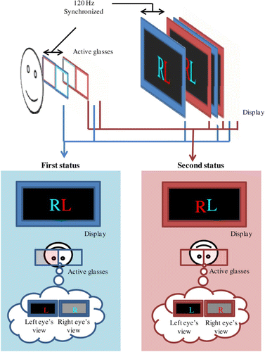
shows the basic idea of the full-color anaglyph system. An observer can see the image through the active color filter. As the left- and right-eye glasses transmit different wavelengths of light, the left and right eyes observe different images. While the original anaglyph method permits only monochromatic 3D images because of its passive color filter, this system allows full-color 3D images by switching the color filter property.
The left bottom part of illustrates the first status of the full-color anaglyph system. This status is identical to that of the normal anaglyph system. The right-eye glass transmits cyan (blue + green) light, and the left-eye glass transmits red light. The second status shown at the right bottom part of is the exact opposite of the first status. The right-eye glass transmits red light while the left-eye glass transmits cyan light.
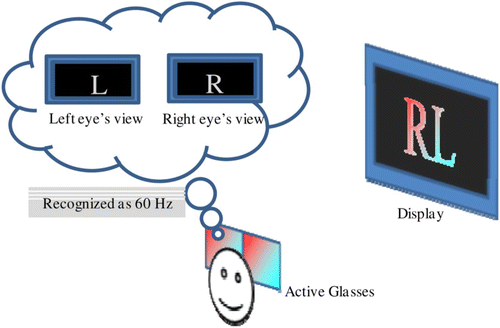
When the first and second statuses are switched rapidly and repeatedly, the observer can watch full-color anaglyphs. shows how the observer sees the full-color 3D images. The synchronized display panel and the active color filter are toggled between the first and second statuses. Due to the afterimage, at over 1/60 sec, an observer senses both the red and cyan images together, and sees the full-color images. As the left and right eyes watch different images, the observer watches full-color 3D images, as shown in .
2.2. System overview
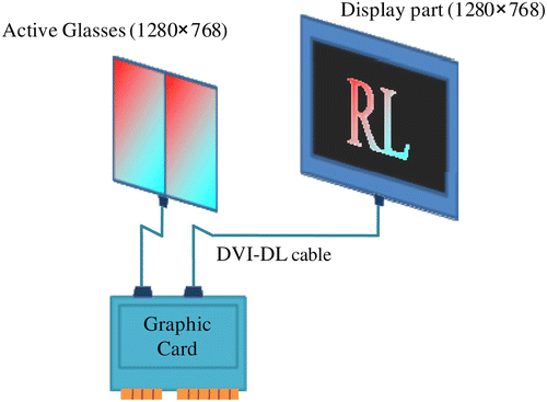
To realize the idea proposed in section 2.1, a system was designed, consisting of two 3D monitors (Samsung 2233RZ) and a standard PC. One monitor was for display, and the other was used as an active color filter. The monitors were connected to one graphic card as a dual system. For the mass calculation performed while displaying 120 Hz contents, a high-quality CPU and a graphic card were needed. For the CPU, an Intel i7 processor was used. This system requires two graphic cards with an SLI connected thereto. Two NVIDIA GTX 470 graphic cards were also used.
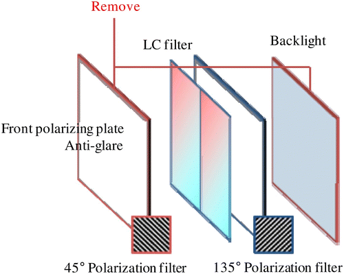
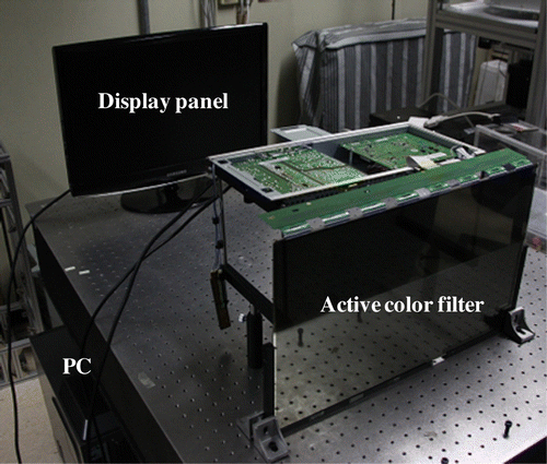
One of the monitors was disassembled and was used as an active color filter. First, the backlight part was removed from the monitor. The liquid crystal panels of the monitor consisted of a front polarizing plate (45°), liquid crystal, and a rear polarizing plate (135°). As the front polarizing plate was anti-glare, the liquid crystal panel was not transparent. Therefore, the front polarizing plate also had to be removed. Nevertheless, the remnant liquid crystal diffuses light slightly, but it is transparent enough to observe 3D images. The whole process of making an active color filter from a liquid crystal monitor is shown in .
When the backlight part and the front polarizing plate are removed, the liquid crystal panel acts like an active color filter by displaying the transmitting color. For example, to transmit red light, the liquid crystal panel should display red light (R=255, ), and for a cyan-light-transmitting color filter, the liquid crystal panel should display cyan light (R=0,
).
The resolution of one monitor was . As two monitors were connected to one graphic card as a dual system, the whole resolution was
. The left half
was the display part, which displays the switching anaglyphic images. The right half
, however, was an active-glasses part. The active-glasses part was further subdivided into two parts: the left half
for the left eye, and the right half
for the right eye. Therefore, the switching image included both the display part and the active-glasses part. The overall system is illustrated in .
3. Experiment
shows the experimental setup of the full-color anaglyph system. The monitor is the display panel operating at 120 Hz. The front transparent liquid crystal panel is an active color filter. The observer sees the 3D image through the transparent color filter.
For the experiment, proper image rendering for this system was needed. There was a need to switch the two anaglyph images by 120 Hz for the static image. The two anaglyph images corresponded to the first and second statuses mentioned in Section 2.1. MATLAB and openGL were used for image rendering.
3.1. Left/right-eye image separation test
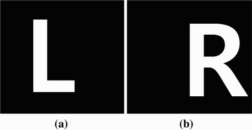
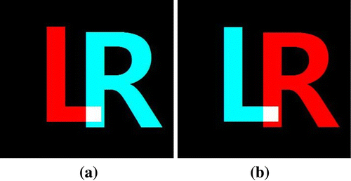
The first step was to test the separation of the left- and right-eye images. To determine the separation clearly, character images were used in the experiment. The left-eye image was the capital letter ‘L’, and the right-eye image was the capital letter ‘R’. As much of the image was filled with a black matrix, the result of the experiment plainly showed crosstalk. shows the original image that was used in the experiment. After image rendering, two images for the first and second statuses were achieved, as shown in .
3.2. Experiment with stereoscopic images
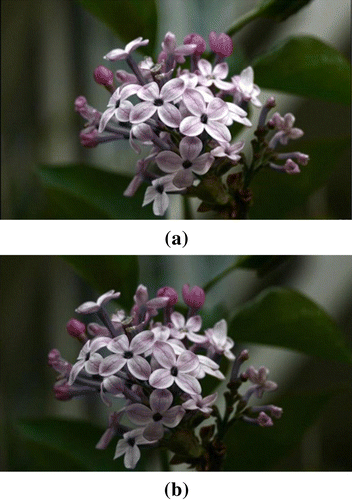
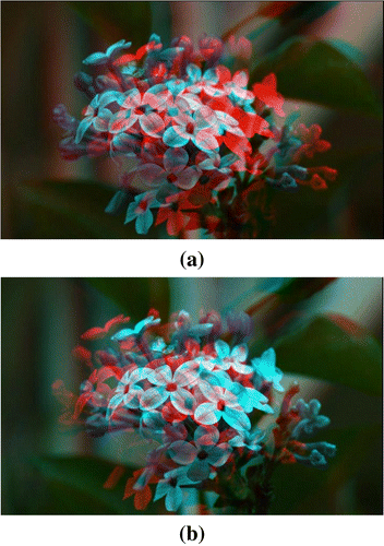
The second step was to apply this system to stereoscopic images. For the experiment, stereoscopic images were needed. Left/right-eye images from a 3D camera were used. A close-up picture of a lilac flower was used, for clear comparison. shows the original left/right-eye images and shows the images that were achieved for the first and second statuses after image rendering.
4. Results
4.1. Left/right-eye image separation test
shows the resulting images of the image separation test. shows the left-eye view, and shows the right-eye view. The left-eye view mainly shows the capital letter ‘L’, and the right-eye view mainly shows the capital letter ‘R’. shows that the images are separated by the synchronized active color filter.
Figure 10. The results of the image separation experiment: (a) the left-eye view and (b) the right-eye view.
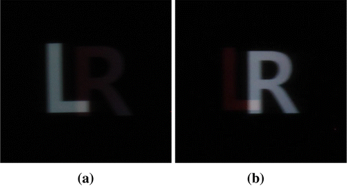
The resulting images, however, show some crosstalk. ‘R’ is dimly seen in the left-eye view, and ‘L’ is faintly seen in the right-eye view. As these images are filled with a black matrix, which plainly shows crosstalk, some crosstalk in these resulting images can be negligible. From this point of view, the resulting stereoscopic images should be better than these results.
The results also contain some blur, as shown in . This is because the active color filter slightly diffuses light. As the active color filter is designed as a part of the display panel, it has inappropriate characteristics for active glasses. If the active color filter is designed as active glasses, this problem will disappear.
4.2. Experiment with stereoscopic images
shows the results of the experiment with stereoscopic images. Compared with , and are the same as the original left/right-eye images. The images are separated clearly, as expected. The comparison of and clearly shows the disparity between the two. Therefore, the observer can see full-color 3D images.
Figure 11. The results of the experiment with stereoscopic images: (a) the left-eye view and (b) the right-eye view.
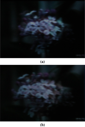
The result also shows some crosstalk, however, as shown in , but the crosstalk is not revealed as much as the crosstalk in is. Although there is some crosstalk and blur, the system provides a full-color 3D display, as expected.
5. Conclusion
Presented herein is a full-color anaglyph system using an active color filter. This system was designed with two 120 Hz display panels. One monitor is for the display, and the other is for the active color filter. The monitors are connected to one graphic card, as a dual system. An active color filter is obtained by disassembling a 3D monitor. To confirm the effectiveness of the proposed method, an experiment was conducted on the system. The results were full-color 3D images, as expected.
This system overcomes the monochromatic 3D image, which is the major weakness of the original anaglyph system. This system displays full-color 3D images with an active color filter. Furthermore, a novel method of making an active color filter from a liquid crystal display monitor was developed. An active color filter can be generated and controlled with a standard PC by displaying the transmitting light. Using this method, a synchronized liquid crystal shutter can easily be realized.
As a liquid crystal panel drives information line by line, it is difficult to synchronize the display panel with active glasses if the sizes of the panels are different. Practically, the size of active glasses is much smaller than that of the display panel. Therefore, a special driving technique is needed for synchronization. From this point of view, it would be proper to conduct follow-up research to apply the existing driving technique of the shutter-glasses method to the developed system.
Acknowledgements
This work was supported by the National Research Foundation of Korea for the Advancement of Science and Creativity (2010-11-011; A Full-Color Anaglyph 3D Display System Using Active Color Filter Glasses).
Additional information
Notes on contributors
Jonghyun Kim
These authors contributed equally to this work.Younghoon Kim
These authors contributed equally to this work.References
- Zone , R. 2002–2003 . Stereo World , 29 ( 11 )
- Gatesy , S. M. , Shubin , N. H. and Jenkins , F. A. 2005 . Palaeontol. Electronica , 8 ( 10 )
- Wood , A. J. and Rourke , T. 2004 . Proc. SPIE-IS&T Electron. Imag. , 5291 ( 354 )
- Benzie , P. , Watson , J. , Surman , P. , Rakkolainen , I. , Hopf , K. , Urey , H. , Sainov , V. and von Kopylow , C. 2007 . IEEE Trans. Circ. Syst. Video Technol. , 17 ( 1647 )
- Lee , B. , Park , J.-H. and Min , S.-W. 2006 . Digital Holography and Three-Dimensional Display , New York : Springer . Ch. 12
- Javidi , B. and Okano , F. 2002 . Three Dimensional Television, Video, and Display Technology , New York : Springer .
- Poon , T.-C. 2009 . J. Opt. Soc. Korea , 13 ( 406 )
- Getty , D. , D'Orsi , C. and Pickett , R. 2008 . Lect. Notes Comput. Sci. , 5116 ( 74 )
- Jahne , B. 1992 . Digital Image Processing: Concepts, Algorithms and Scientific Applications , 196 New York : Springer .
- Wood , A. J. , Yuen , K.-L. and Karvinen , K. S. 2007 . J. Soc. Inform. Display , 15 ( 889 )
