Abstract
The universal current reversal method is used for the simultaneous measurement of response time (τ), azimuthal angle (ϕo), spontaneous polarization (P S), and rotational viscosity (γϕ) of two ferroelectric liquid crystals (FLCs). The application of AC field in FLCs results in reorientational current, which is further analyzed to obtain various parameters. The variation in the parameters with temperature follows the typical trend predicted by the theory. The theoretical curve fits well into the experimental data. Its comparison with traditional current reversal method is confirmed to address certain limitations of that method.
1. Introduction
Ferroelectricity in liquid crystals is a specific property of some chiral smectic phases. It was first discovered by Meyer et al. in 1975 with the use of a classic liquid crystalline material, p-decycloxy benzylidine p-amino-2-methylbutyl cinnamate, which exhibited chiral smectic C (SmC*) phase Citation1. Ferroelectric liquid crystals (FLCs) are ideally suitable for display devices owing to their inherent tendency to form oriented, optically birefringent domains, interesting electro-optic properties, and fast switching feature Citation2–8.
The major parameters, which determine the switching time of FLC cell, are polarization (P
S) and rotational viscosity . A significant experimental and theoretical study has been carried out to evaluate these parameters Citation9–13. There are, however, three basic methods developed for the measurement of P S: Pyroelectric method Citation9, Sawyer Tower method Citation10, and a set of techniques based on current reversal Citation11–14. The continuing interest in these materials required further development of measurement techniques.
Later on, a universal procedure was presented in which these parameters could be measured simultaneously Citation15 Citation16. Along with these parameters, it was also possible to measure azimuthal angle, ionic conductivity, and complex permittivity of the sample in the same experiment. The method has turned out to be an improvement of the current reversal method Citation15 Citation16. Although a number of research groups have studied FLC parameters using the current reversal technique, our literature survey revealed only two groups among those who introduced the method Citation15 Citation16 have used the universal method to measure these parameters. No one has studied high polarization and short-pitch FLC using this method, and no one until now has studied the advantage of the universal method over traditional current reversal method for measuring response time.
In the present paper, an attempt is made to study the parameters of two FLC materials: Equation(1) low spontaneous polarization FLC and Equation(2)
high spontaneous polarization FLC, using the universal current reversal technique. The method is also observed to remove the shortcomings significantly in the response time measurements of earlier method.
2. Experimental
Investigations have been performed on two well-known FLC mixtures: FLC-6304 and SCE-4. The FLC-6304 exhibits ferroelectric SmC* and SmA* phases with corresponding transition temperatures given by SmC*-SmA-Isotropic: 59°C, 64°C. It has large spontaneous polarization (110 nC/cm2), short pitch (0.35 μm) and large tilt angle (27°) Citation17. The other ferroelectric material SCE-4 shows the LC phases with corresponding transition temperatures SmC*-SmA-N-Isotropic: 57°C, 88°C, 122°C and polarization 5 nC/cm2.
The thermotropic mesomorphism and the transition temperatures of these materials have also been confirmed by the optical thermal polarizing microscopy and differential scanning calorimeter (DSC-7 Perkin-Elmer, Mumbai, India). The LC mixture was filled in the planar cells 25 and 5 μm thick by the capillary action at their isotropic temperature. A well-aligned texture was obtained by cooling down the sample to room temperature at 0.1°C/minute. The microtextures of the samples were visualized through the polarizing microscope (Model Select P1, Dewinter, New Delhi, India) interfaced with computer.
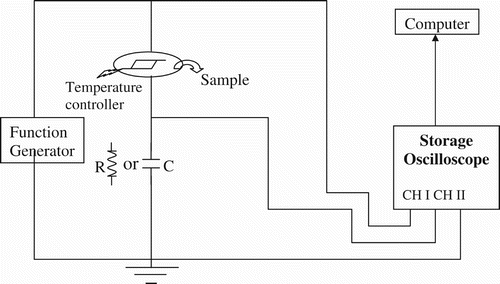
A schematic diagram of the setup used for the measurements of FLC's physical parameters is shown in . Here, the square wave was applied to the sample and the output current was integrated from an external capacitor. The output waveform is then obtained on a digitizing storage oscilloscope. The circuit is a modified form of current reversal method Citation14–16 (where resistance is used in the external circuit) and measures response time (τ), azimuthal angle , spontaneous polarization
, rotational viscosity
, and dielectric permittivity
in a single experiment. In the traditional method, the change in resistor value changes the value of response time. This limitation is also significantly removed by the use of a capacitor.
3. Theoretical considerations
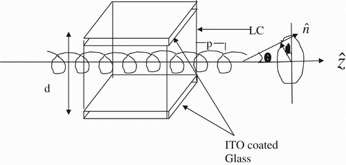
The SmC* structure in the relaxed state (see ) is helicoidal and can be represented in terms of a one-dimensional model which gives the azimuthal angle, ϕ, as a function of z along the helical axis, where
is the wave vector of the helix pitch p. The angle between director [ncirc] and layer normal [zcirc] is called tilt angle θ. The study of electrooptic switching in SmC* phase is based on the following equation:
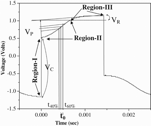
Figure 3. Shape of the waveform obtained after integration of the input signal from the external capacitor.
Where is switching time,
is initial azimuthal angle, and
. The polarization part of the voltage across the capacitor is a function of ϕ (t), as presented below Citation15
Citation16:
4. Results and discussion
4.1 Measurement of FLC parameters
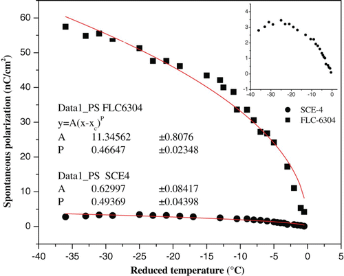
The various electro-optic parameters, as determined from the above procedure, follow trends predicted by theory and their magnitude matches with those measured using other methods. The values of these parameters determined by the traditional method are published elsewhere Citation18. shows the behavior of polarization with reduced temperature (, where
is the transition temperature from SmC* to SmA phase) for 5 μm thick samples. As theoretically expected, it is observed to follow the power law:
Figure 4. Variation in spontaneous polarization as a function of reduced temperature for FLC mixtures. Inset: Variation in spontaneous polarization for SCE-4.
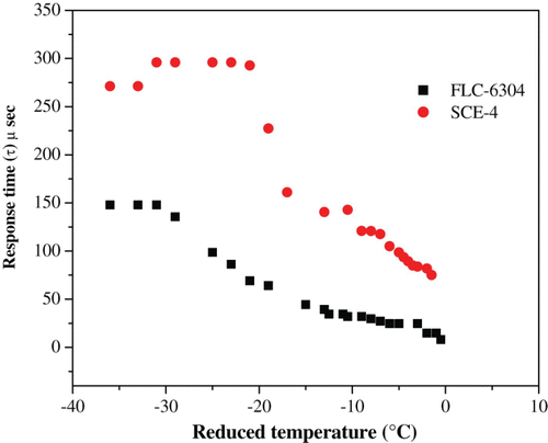
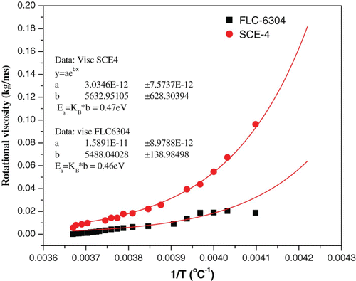
The response time has been calculated using EquationEquation (8). The variation in switching response as a function of temperature is shown in . It obeys a typical Arrhenius behavior, as expected in the FLC mixtures. The temperature dependence of rotational viscosity γφ of the liquid crystals as calculated using EquationEquation (9)
is given in . γφ shows an exponential decrease with temperature far from the phase transition. It also shows a sharp drop near the transition temperature. These experimental results agree well with the mean field theory and follow a behavior given by the following equation:
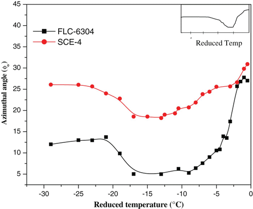
The azimuthal angle can also be determined by substituting the value of response time in EquationEquation (7). The variation in azimuthal angle with temperature, as calculated from this method, is shown in . Since the azimuthal angle () is related to the wave vector by relation
, it follows the trend similar to wave vector. According to the theoretical predictions, the variation of wave vector of pitch with temperature follows the equation Citation24–27:
Figure 7. Variation in azimuthal angle as a function of reduced temperature for FLC mixtures. Inset: Theoretical curve of wave-vector variation.
The permittivity can also be measured in the same experiment by using EquationEquation (5). The contribution from DC conductivity can also be obtained by using the assumption that the change in ion concentration is negligible in the case of field reversal; hence, the cell resistance is constant. To measure the conductivity, a linear regression is applied to the corresponding part of the waveform (see ), and then a straight line is subtracted from the output signal. However, this method is not very accurate for conductivity measurements.
4.2 Comparison with traditional current reversal method
The present technique, in addition to being universal, substantially addresses the limitations in response time measurement of earlier current reversal method, as confirmed in this section. The response time measurements have been carried out using the traditional method (standard resistors in external circuit) and the present technique. We measured the response time using different resistances in the range of 1–2 kΩ and capacitor from 10 to 100 nF. The variation in response time (τ) with resistance and capacitance for FLC-6304 samples having cell thickness 5 and 25 μm is shown in and , respectively.
Figure 8. Variation in response time as a function of (a) resistance and (b) capacitor for FLC-6304 samples.
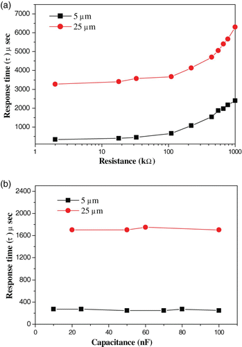
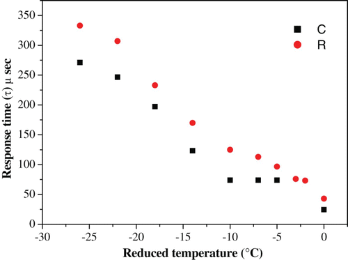
It is interesting to note that the change in capacitance () has a negligible effect on response time, whereas it increases as resistance increases (). This change is steep beyond 20 kΩ. Although the response time is found to approach a constant value at lower resistances (<20–2 kΩ) in both cells, it is difficult to obtain an output waveform due to the vanishing signal. Response time was determined precisely by extrapolating the curve obtained in . The value thus obtained was approximately the same as in the case of capacitor method (∼200 μ second, at room temperature). The temperature dependence of the response time ‘τ’ for FLC- 6304 sample with cell thickness 5 μm using both methods is shown in . Although there is a difference in magnitude of τ, it shows an Arrhenius behavior in both cases as predicted by theory.
Figure 9. Variation in response time as a function of reduced temperature , using capacitor and resistor in the circuit for FLC-6304 sample.
4.2.1 Theoretical model
Theoretically, we consider that with the resistor method, the voltage generator drives an [ series (R)] equivalent dipole, whereas with the capacitor method, the voltage generator drives an [
series
] dipole. In the former case, the dependency of R vanishes for
R. However, a vanishing effect also implies a vanishing signal. It is therefore impossible to go below a certain value of R, and the dependence of response time on R cannot be removed. This explains our variation in response time with resistance and its comparatively larger value at the higher resistance.
In the latter case, while C
osc can be safely neglected (13 pF), cannot, as it is 1 MΩ. However, the effect vanishes for
. While for low C, the case reappears due to
, the very large value of C is restricted since it results in a vanishing signal. However, it is easy to select a capacitance value that gives the desired output waveform with negligible dependence on C. In our case, a negligible effect of C on response time using capacitance in the range 10–100 nF was observed, as shown in .
These theoretical considerations explain the changing value of ‘τ ’ with resistance and how this effect can be minimized using the universal method.
5. Conclusions
Parameters including azimuthal angle, response time, spontaneous polarization, and viscosity among others are measured in a single experiment from the relaxation voltage curve corresponding to the repolarization current of the two FLC materials with high and low polarization, respectively. Our results agree with the findings as predicted by the theory. The temperature dependence of polarization is observed to follow the square-root mean field law, and the critical exponent of the polarization curve is obtained to be very close to 0.5 eV. Activation energy of the materials as observed from the rotational viscosity curve is perceived to be in the theoretical limit.
This study's method is compared with the traditional current reversal method. A change in response time with output resistance is observed, a limitation that is significantly removed by the present technique. A theoretical explanation has also been given to justify the above results.
References
- Meyer , R. B. , Liebert , L. , Strzelecki , L. and Keller , P. 1975 . J. de. Phys. Lett. (Paris) , 36 : L69
- Bersnev , L. A. , Blinov , L. M. , Osipov , M. A. and Pikin , S. A. 1988 . Mol. Cyst. Liq. Cryst. , 158A : 1
- Kimura , Y. and Hayakawa , R. 1993 . Jpn. J. Appl. Phys , 32 : 427
- Raina , K. K. and Coles , H. J. 9th IEEE Int. Symp. on Appl. of Ferroelectrics, USA . CH3416-50-7803, IEEE, 788
- Raina , K. K. and Ahuja , J. K. 1999 . Mol. Cryst. Liq. Cryst. , 338 : 125
- Clark , N. A. and Lagerwall , S. T. 1980 . Appl. Phys. Lett. , 36 : 11
- Bersnev , L. A. , Chigrinov , V. G. , Drgachev , D. I. , Poshidaev , E. P. , Funfschilling , J. and Schadt , M. 1989 . Liq. Cryst. , 5 : 1171
- Funfshcilling , J. and Schadt , M. 1989 . J. Appl. Phys. , 66 : 3877
- Ahuja , J. K. and Raina , K. K. 2000 . Jpn. J. Appl. Phys. , 39 : 4076
- Blinov , L. M. , Barnik , M. I. , Ozaki , M. , Shtykov , N. M. and Yoshino , K. 2000 . Phy. Rev. E, , 62 ( 6 ) : 8091
- Madhumohan , M. L.M. , Gaud , B. V.S. , Kumar , P. A. and Pissipati , V. G.K.M. 1999 . Mat. Res. Bull. , 34 ( 14 ) : 2167
- Bawa , S. S. , Biradar , A. M. and Chandra , S. 1987 . Jpn. J. Appl. Phys. , 26 : 189
- Bawa , S. S. , Biradar , A. M. , Saxena , K. and Chandra , S. 1988 . Rev. Sci. Instrum. , 59 ( 9 ) : 2023
- Khosla , S. and Raina , K. K. 2004 . Indian J. Pure Appl. Phys. , 42 : 49
- Panarin , Y. P. and Vaksman , V. M. 1992 . Mol. Mater. , 1 : 147
- Panov , V. , Vij , J. K. and Shtykov , N. M. 2001 . Liq. Cryst. , 28 ( 4 ) : 615
- Hoffmann La Roche, Ltd, Basel, Switzerland
- Khosla , S. , Sood , N. , Raina , K. K. and Bawa , S. S. 2010 . Mol. Cryst. Liq. Cryst , 524 : 119
- Srivastava , S. L. 1993 . Proc. Natl. Acad. Sci., India, , LXIII : 311
- Srivastava , S. L. and Agarwal , V. K. 1993 . Indian J. Pure Appl. Phys. , 31 : 59
- Miyata , H. , Maeda , M. and Suzuki , I. 1996 . Liq. Cryst. , 20 ( 3 ) : 303
- Wrobel , S. , Hiller , S. , Pfeiffer , M. , Marzec , M. and Haase , W. 1995 . Liq. Cryst. , 18 ( 1 ) : 21
- Khoo , I. C. 1993 . Optics and Non Linear Optics of Liquid Crystals , Singapore : World Scientific .
- Carlsson , T. , Zeks , B. , Fillipic , C. , Levstik , A. and Blinc , R. 1988 . Mol. Cryst. Liq. Cryst. , 163 : 11
- Levstik , A. , Carlsson , T. , Fillipic , C. , Levstik , I. and Zeks , B. 1987 . Phys. Rev. A, , 35 ( 8 ) : 352
- Fillipic , C. , Carlsson , T. , Levstik , A. , Zeks And , B. and Blinc , R. 1988 . Phys. Rev. A, , 38 ( 10 ) : 5833
- Carlsson , T. , Zeks , B. , Fillipic , C. and Levstik , A. 1990 . Phys. Rev. A, , 42 ( 2 ) : 877
