Abstract
Light intensity degradation is one of the most important parameters in the design of organic light-emitting diodes (OLEDs) for image applications, and it is usually obtained through time-consuming stability tests. The lifetimes are estimated based on the well-known empirical reciprocal relationship between the initial brightness and the half-lifetime, which is assumed to be always valid for all devices. In this work, it was used as a chemical kinetics approach for modeling the light output in time under constant current operation. Through this approach, an equation with only two parameters, one for OLED light output in time and another for half-lifetimes, was obtained. This approach was applied to stability tests for three different OLEDs to determine how their features affect the kinetic parameters and to compare such parameters for OLEDs operating at two temperatures, 22°C and 70°C, to determine if they have a correlation with thermal stability.
Introduction
Since Tang and Van Slyke [Citation1] made the first organic light-emitting diode (OLED) prototypes, the OLED designs have evolved, and many different OLED preparation techniques and structures have been developed [Citation2]. Meanwhile, many new materials were synthesized to improve the charge carrier mobility, light output, operation thermal stability, etc. [Citation3] In fact, in the last three decades, all the related researches and developments were aimed at coming up with devices with the highest light output and longest lifetime for commercial applications in image displays. A display that uses OLEDs is expected to have a better color display because of the many advantages of OLEDs, such as high quantum yield, wide-viewing angle, high contrast, and quick response speed. In addition, they can be made with flexible substrates and lower production costs. There is still a problem, however, with regard to their long-term brightness performance. OLED degradation is mainly caused by morphological instability or by the crystallization of amorphous organic films [Citation1], the electrochemical decomposition of organic materials [Citation4], and the poor contact between the organic layer and the electrodes [Citation4,Citation5], among others. Tang and Van Slyke, who did an early work on OLEDs, pointed out the crystallization of the organic material into the hole transport layer [Citation6] as a main concern for reducing the performance of OLEDs. The development of some new materials with high heat stability [Citation7] and the lowering of the Joule heating of operation improved the emitting layer efficiency to the level required.
The characterization of OLED performance in long-term operation is one of the important issues of OLED development, but it is not easy to directly compare the performance of different OLED structures in long-term operation because of the unique specificities of OLEDs, which can have a manifold of different functional layers and materials. The lifetimes of OLEDs may be determined, by conducting stability tests on OLEDs under controlled electrical voltage and current conditions, to measure the time required for decreasing the intensity of light emission by half the value of some initial light intensity. This lifetime, called “half-life of OLED”, is correlated with the useful time for imaging applications, but it depends largely on the structure of the OLED and on the materials used in the charge transport layer of the OLED under the initial and operating conditions, which makes it difficult to establish the correlations among different OLEDs using an empirical model. Furthermore, even when OLEDs are operated under optimal conditions to minimize their failure breakdown (no moisture and inert atmosphere, encapsulated and sealed box, high-thermal-stability compounds, low current operation, etc.), the light emission decreases continuously, indicating the intrinsic degradation of the organic materials in the OLEDs. Although there have been many experimental studies on the intrinsic degradation of OLEDs, there is still no empirical model that can relate a kinetic process between this degradation and fading light emission, which makes it even more difficult to interpret and compare the lifetimes of OLEDs.
In this work, a theoretical approach was used to model the intrinsic degradation of OLEDs, using a generalized rate equation based on chemical kinetics for analyzing the lifetime experiment results. The approach was used to study the intrinsic degradation of three OLED structures under different operating conditions, which allowed a general function that fits the light intensity in time to be obtained, and to compare the parameter models of all devices at two temperatures: 22°C and 70°C.
Kinetic analysis
The electroluminescence intensity for an OLED with thickness d running on stationary driving condition is defined as the photon flux divided by active emission area and it is given by equation (1) [Citation8]:
The kinetic equations describing the populations of free charge carriers under steady-state conditions are
From a chemical viewpoint, light intensity can be considered a product of the reaction , where e− and h+ are free electron and hole carriers and hν is the photon. If it is assumed that the concentrations of the carriers of the electrical charge are a fraction of the electron injection current, then under constant current conditions, these concentrations should remain constant. The concentrations of electric charge carriers also change with time, however, because other processes also occur within the organic layers of OLEDs, such as exciton recombination, molecular decomposition of organic compounds, and crystallization. Thus, the light intensity decay during stability testing should be proportional to the total concentration of free electric charge carriers. As such, a rate equation can be used for analyzing the kinetics of decay of the light intensity of OLEDs.
Using chemical kinetics, the derivative of light intensity measured with respect to time under constant electron injection current conditions is assumed to be proportional to the light intensity raised to the nth power, as in Equation (5).
In chemistry kinetics, the measured time derivate of the light intensity decay under a constant injection current is assumed to be proportional to the light intensity raised to the nth power:
The aforementioned reaction rate equation has two main applications. If exponent n and rate constant K are known, the rate of the process from any initial condition can be predicted, and the lifetime can be calculated. Another application is a guide to understanding the relation between the kinetic parameters and the operation conditions with the reaction process. Exponent n is related to the concentration (light intensity) influence with the decay process, such as first-order reactions, which have n=1 exponential processes. Such rate equation must be obtained through an experiment.
As the aforementioned rate equation is a differential equation, it must be integrated to find the light intensity as a function of time. In this simple case, an analytical solution is easily obtained:
Equation (7) is a function of the light intensity under the condition that the electron injection current is stationary when the rate equation is integrated over time t. It is important to note that some experimental observations can be related to it. In fact, one reciprocal relationship between the OLED half-lifetime, t1/2, and the initial light intensity Θ0 was observed by Tang in his early OLED studies, namely , where
was a constant dependent on the initial intensity.
By substituting with t=t1/2, it can be easily shown through the rearrangement of Equation (7) that the interval half-life of an OLED is given by Equation (8), which exhibits a reciprocal relationship constant between Θ0 and t1/2, and this constant is defined by the kinetic parameters and the initial light intensity:
Another important feature is the linearity relation between the light intensity decay and the time observed under the constant current operation of OLED that correlates with the time at the beginning of the operation. These can be shown with the rate equation. Indeed, a linear equation between the light intensity and time can be observed by considering a binomial expansion of Equation (7):
Assuming that m=1/(1−n) and , and using only the linear terms of Taylor expansion in Equation (9), one can approximate the relative luminous intensity for the expression in Equation (10), which shows that the relative light intensity should be almost linear at the start of the intrinsic degradation process:
Another noteworthy feature of this rate equation approach is related to the necessity of running a long-term test where hundreds or thousands of hours can be spent obtaining the half-lifetime constant. Taking into account the fact that the time required for light intensity decreases by a fraction 1/f of its initial value, Equation (8) can be rewritten as
When an 1/f value greater than 1/2 is used in Equation (11), the reaction order and rate constant can be determined in a much shorter time than in the stability test. This time reduction from the stability test can be achieved by choosing 1/f=3/4, 4/5, 5/6, etc. In fact, by making use of a log–log plot for the relative intensity at time t1/f, one can obtain a linear trend, which can be adjusted via linear regression using the following equation:
After obtaining parameters n and K for fraction 1/f of initial light intensity can be estimated using Equations (8) and (11). It is easy to show that t1/f and t1/2 are related using the following equation:
Results and discussion
The instrumental details of preparing OLED structures together with the stability experiment setup were described in detail in the early works [Citation9–12]. Specifically, stability tests for determining the intensity vs. time were performed using the alternating current (AC) driving conditions. The duty cycle of the AC bias was 50%, with a 62.5 mA/cm2 constant current bias in the forward direction and a 15 V constant voltage bias in the device reverse direction, at a frequency of 1 kHz. As the injected current at the reverse bias cycle was negligibly small, AC driving resulted in an average direct current of 31.25 mA/cm2. The electroluminescence and peak forward bias voltage of the devices under testing were simultaneously monitored and continuously recorded using a computer-controlled data acquisition system.
To show how the rate equation can be applied to the analysis of the results of the stability testing of OLEDs, the data obtained for three different pairs of structures subjected to stability tests under similar operating conditions but at two different temperatures were used. A representative of such structures is the multilayer OLEDs, specifically two double-layered OLEDs (DL-OLED), two OLEDs with a hole-block layer (HBL-OLED), and two OLEDs with a doped emitting layer (DEL-OLED). The features of these structures are listed in . For each pair of OLEDs, one was tested at 22°C and the other at 70°C.
Table 1. OLED devices with the structure features used in the lifetime experiments.
The light intensity of the aforementioned devices was measured for a long runtime, and the experimental lifetimes were obtained by directly comparing the initial light intensity and the time for the light intensity reduced to half value. In all the cases, an algorithm of Levenberg–Marquardt iteration was used for the nonlinear least-squares fitter in the function fitting process. The parameters were obtained to maximize the correlation factor R2 and to minimize the χ2 test. The parameters were fitted through a weighting method with a scaled error by the squared root error of the reduced χ2, which allowed the residues for all the fittings to be minimized, as shown in all the figures.
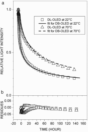
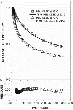
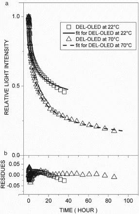
In the comparison of the stability data of the tests shown in – for DL-OLED, HBL-OLED, and DEL-OLED, respectively, it was observed that the rates of reduction of light intensity due to the intrinsic decay were largely dependent on the structure of the OLEDs, the conditions of the initial light intensity, and the temperature, as described in recent works [Citation7,Citation11–14]. In these cases, it was observed that the parameters of the rate equation exhibited some interesting features. In , plot (a) shows the light intensity decay with the fitting, and plot (b) presents the residue curves for the DL-OLED at 22°C and 70°C, respectively. The kinetic parameters went in opposite directions as the temperature rose, as shown in , and the rate constant (K) increased while the reaction order (n) decreased along with the initial light intensity (Θ0). Using Equation (8), the half-lifetimes (t1/2) were computed and were compared with the experiment values. In , plots (a) and (b) show the light intensity with the fitting and the residue curves for the HBL-OLED at 22°C and 70°C, respectively. In this case, the temperature had less effect on the kinetic parameters, as shown in . Indeed, such parameters showed opposite trends with regard to the DL-OLED: at 70°C, n was the highest, and at 22°C, Θ0 and K were lower. It was also noted that for both devices, the values of the K and n parameters were within similar ranges (10−10 to 10−8). It has to be pointed out that although the OLED structures had different features, they exhibited the same intrinsic degradation processes. On the other hand, the DEL-OLED intensity was fitted by a rate equation with very different parameters, and exhibited strong dependence on temperature, as shown in . In , plot (a) exhibits the DEL-OLED light intensity with the fitting, and plot (b) shows the residue curves at 22°C and 70°C, respectively. For the doped emitting layer, the OLEDs featured very different rate equations at 22°C and 70°C, respectively. At 22°C, exponent n was higher and indicated a stronger dependence on the charge carrier concentration compared to the other devices. Rate constant K was lower, however, compared to the other OLEDs. At 70°C, such parameters were closer to the DL-OLED and HBL-OLED parameters, but the lifetime was the lowest for all the OLEDs. Also, it was observed that for DEL-OLED at 22°C, exponent n was higher, while at 70°C, it was near the other OLED values. One possible explanation for this feature is that in the DEL-OLED light emission process at 22°C, the charge carrier recombination and energy transfer to the emitting layer were combined, which would be one more complex mechanism. On the other hand, at 70°C, the emission process should be mainly due to the charge carrier recombination if the energy transfer to the emitting layer is not more effective; therefore, the DEL-OLED parameters were similar to those of the other OLEDs.
Figure 1. (a) Relative light intensity with fitting curves and (b) respective residues of fitting curves for double-layer OLED at 22°C (□) and 70°C (▵).

Figure 2. (a) Relative light intensity with fitting curves and (b) respective residues of fitting curves for hole-block layer OLED at 22°C (□) and 70°C (▵).

Figure 3. (a) Relative light intensity with fitting curves and (b) respective residues of fitting curves for doped emitter layer OLED at 22°C (□) and 70°C (▵).

Table 2. Kinetics parameters and the calculated and experimental half-lifetimes for the OLED.
Furthermore, comparing the computed t1/2 values with fitted parameters to those obtained experimentally, as noted in the last two columns of , it can be seen that the averaged accuracy was about 3.6% and that it was less accurate only for HBL-OLED at 70°C.
Considering the structures of OLEDs and the fact that the majority charge carriers are electrons, it should be noted that the effect of the temperature on the kinetic parameters is related to the mobility of the charges in the layer, as already stated above. In this study, the light intensity was found to be proportional to the current injection, and it was found that the recombination of the charge carriers should be made proportional to the hole and electron carrier concentrations through a bimolecular process. It can then be assumed that the intrinsic degradation of organic compounds in OLEDs should be attributed to the concentration of electrical charges at the interface of the charge transport layer. Faster light intensity decay is an indication of a higher rate of degradation of the organic compounds. The balance between the hole and electron carrier concentrations should be the key point in quantum efficiency. When the electron concentration is greater than that of the holes, or vice versa, accumulation of negative charges (or positive) occurs, thereby accelerating the degradation of the organic compounds, which is more effective for positively charged organic compounds that are less stable [Citation9,Citation11,Citation12].
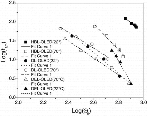
shows a linear relationship between log(t1/f) and for all the studied OLEDs, where it was set at 1/f=3/4 and where Θ0 was chosen in different times, corresponding to the initial times for estimating the respective t1/f values. As can be seen, all the OLEDs really exhibited linear trends between log(t1/f) and
. Using the linear function y=ax+b, the following parameters were obtained via linear regression. Intercept b and slope a can be seen in . These estimative are almost as inaccurate as those in . The accuracy can be improved, however, by using more data in the test interval. This can be done by effectively increasing the rate of acquiring the luminous intensity of the OLED. This is a fairly simple way of increasing the signal-to-noise ratio. Another important issue is that the behavior of OLEDs in the first seconds or minutes of operation may often be disregarded without compromising the analysis, improving the regularity of the light intensity.
Figure 4. Linear fitting for estimating the OLED half-lifetimes using the 1/f lifetime equation (12). (■) HBL-OLED (22°C), (□) HBL-OLED (70°C); (▲) DEL-OLED (22°C), (▵) DEL-OLED (70°C); and (•) DL-OLED (22°C), (gcirc) DL-OLED (70°C).

Table 3. Kinetics parameters obtained from fractional relative light intensity using 1/f=3/4.
Conclusion
In this work, a faster way of analyzing the results of a lifetime experiment is shown, using a generalized rate equation based on the chemical kinetics approach, to compare different OLED structures in different operating conditions, allowing a general function to be obtained for modeling all devices and for calculating the lifetime while using only three kinetic parameters in a shorter time stability experiment. Although this is an empirical and phenomenological study whose main goal was to formalize a way of comparing the lifetimes of many currently existing OLEDs, its assumptions are based on the consolidated consistent observations made in previous studies and the results of theoretical analysis. Thus, it may become the starting point for the development of a more detailed model that takes into account the molecular phenomena and electric charge transport in organic materials.
References
- C.W. Tang and S.A. Van Slyke, Appl. Phys. Lett. 51, 913 (1987).
- S. Forrest, Chem. Rev. 97, 1793 (1997).
- J. Kalinowski, J. Phys. Appl. Phys. 32, R-179 (1999).
- E.M. Han, L.M. Do, N. Yamamoto, and M. Fujihira, Thin Solid Films 273, 202 (1996).
- Y. Sato and H. Kanai, Mol. Cryst. Liq. Cryst. 253, 143 (1994).
- J. McElvain, H. Antoniadis, M.R. Hueschen, J.N. Miller, D.M. Roitman, J.R. Sheats, and R.L. Moon, J. Appl. Phys. 80, 6002 (1996).
- S.A. Van Slyke, C.H. Chen, and C.W. Tang, Appl. Phys. Lett. 69, 2160 (1996). doi: 10.1063/1.117151
- J. Kalinowski, P. Di Marco, N. Camaioni, V. Fattori, W. Stampor, and J. Duff, Synth. Met. 76, 77 (1996).
- Z.D. Popovic, H. Aziz, N.-X. Hu, and P.N.M. dos Anjos, published in Conference Record of the 20th International Display Research Conference, Palm Beach, Florida, 25–28 September, published by Society for Information Display (SID), 2000, pp. 333–336.
- Z.D. Popovic, H. Aziz, N. Hu, P.N.M. dos Anjos, and A. Ioannidis, Proceedings of IS&T's NIP-16: International Conference on Digital Printing Technologies, The Society for Imaging Science and Technology, 2000, pp. 350–353.
- H. Aziz, Z.D. Popovic, N.X. Hu, A.M. Hor, and G. Xu, Science 283, 1900 (1999).
- Y. Hamada, T. Sano, K. Shibata, and K. Kuroki, Jpn J. Appl. Phys. 34, L824 (1995).
- Z.D. Popovic, S. Xie, N. Hu, A. Hor, D. Fork, G. Anderson, and C. Tripp, Synth. Met. 363, 6 (2000).
- P.N.M. dos Anjos, H. Aziz, N.-X. Hu, and Z.D. Popovic, Org. Electron. 3, 9 (2002).