Abstract
Presented is an interferometric modulator display characterized by double layers of liquid crystal (LC) Fabry–Pérot filters. With this design, no polarizers and color filters are needed, and both the color and amplitude can be tuned by electrically controlling the LC's birefringence. Instead of the conventional RGB trisubpixel color scheme, a bisubpixel structure is proposed to render a super-wide color gamut. Through simulations, the device performance was numerically studied. The device was proven to be quite suitable for green-display application.
1. Introduction
Liquid crystal displays (LCDs) are currently ubiquitous in consumer electronics, ranging from small handheld devices to large televisions [Citation1]. In terms of light utilization, however, LCDs, by nature, are not an energy-efficient solution, mainly suffering from polarizers and color filters, which could result in a low optical throughput (typically around 5%) [Citation2]. To date, a number of approaches have been proposed to address this issue. For instance, the replacement of absorptive polarizers with reflective polarizers enables the recycling of light in the backlight unit [Citation3]. A special liquid crystal (LC) panel serving as a stencil mask to provide grayscale modulation was developed as a polarizer-free display [Citation4]. Furthermore, the field sequential color (FSC) driving scheme can eliminate the need for color filters, but the color breakup accompanying moving objects is basically inevitable [Citation5].
To develop an eco-friendly display other than LCDs, Iridigm et al. invented a reflective-type display system based on the interferometric modulation technology [Citation6]. This system offers low energy consumption as well as color rendering, but the inherent bistable nature of microelectromechanical systems greatly limits the resolution and color gamut of the display.
In this paper, an interferometric modulator display featuring double Fabry–Pérot (FP) filters is proposed. A stack of two FP filters with relatively low fineness were tuned in tandem by applying different voltages to LC layers to control the transmission over the entire visible regime (400–700 nm). Instead of a conventional RGB tricolor scheme, a bicolor scheme implemented by only two subpixels was used to render a super-wide color gamut, thereby increasing the resolution by one-third. With the absence of polarizers and color filters but still being able to adjust both the image contrasts and colors, the proposed solution may be a promising candidate for green-display application.
2. Operation principle
2.1 Proposed structure
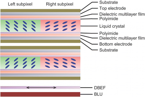
is a schematic drawing of the cross-section of the proposed structure, where LC was sandwiched in between two polyimide layers adjacent to reflective dielectric multilayer films (DMFs) and electrodes to form an FP filter. The top electrode was grounded, whereas the bottom electrode could be driven via thin-film transistors. The LC directors within the upper and lower FP filters tilt in opposite directions for angular-dependence compensation. Each LC interlayer was modulated independently, and a unit pixel was divided into two subpixels. In addition to the two FP filters, a white-light backlight unit (BLU) along with a dual-brightness enhancement film [Citation7] was laminated underneath to emit linearly polarized light in the horizontal direction.
Figure 1. Schematic diagram of the proposed double-layer FP-filter-based LCD system.
2.2 Intensity modulation
To illustrate its operational principle, the transmittance of a single FP filter with one LC interlayer can be expressed as [Citation8]
where
The first term in Equation (1), the maximum transmittance, depends on the reflectance R and absorbance A of the reflective DMFs. The second term is the well-known airy function that determines the central wavelength, where the peak transmission appears. By applying a voltage to the LC interlayer, the average refractive index n of the LC can be tuned to change the phase difference δ, according to Equation (3). This also means that the central wavelength of an FP filter can be adjusted. A single FP filter, however, is incapable of tuning the maximum transmittance, which is the first term in Equation (1).
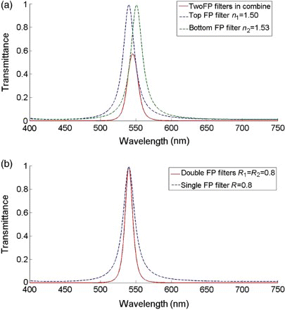
To gain full control over both the wavelength and transmittance in the transmission spectrum, another FP filter is introduced, as can be seen from . The overall transmission spectra of the two FP filters with a slight mismatch in transmission peaks exhibit intensity modulation of the transmitted light, as shown in (a). Moreover, the two FP filters could further narrow the transmission bandwidth so that the color purity of the double FP filters with relatively low fineness F can be improved, as shown in (b).
Figure 2. (a) Transmission spectrum of the top and bottom FP filters with different average refractive indices of the top and bottom LC interlayers, and the overall transmission spectrum. (b) Transmission spectrum of the single and double FP filters when R1=R2=0.8, d=320 nm, and θ1=0.
2.3 Wavelength modulation
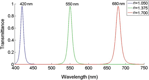
In addition to the control over the transmittance of a certain wavelength, the wavelength tuning ability of a single FP filter by applying different voltages is also preserved in the proposed double-FP-filter structure. As can be seen from , with properly designed parameters, the central wavelength of the transmission peaks could cover the entire visible light range without the presence of any undesired transmission peak by simply controlling the applied voltage on the LC interlayer. This is achieved by optimizing the wavelength separation between the adjacent transmission peaks, which is defined in Equation (5) [Citation8]
Figure 3. Transmission spectrum of a single subpixel (in a double-FP-filter structure) varying when the average refractive index changed with the applied voltages, where R1=R2=0.9, d=200 nm, and θ1=0.
According to Equation (5), an ultra-thin LC interlayer with a thickness d of around 200 nm is required to eliminate the undesired transmission peak within a wide range (400–700 nm). To realize this design, a more sophisticated cell assembly process may be needed to define the cell gap of several hundreds of microns. Moreover, the coverage of the whole visible regime demands a very large LC material birefringence of above 0.65, as shown in the inset of . Although the commercially used LCs exhibit a birefringence of around 0.2, LCs with –0.8 at room temperature have been reported [Citation9].
3. Results and discussion
3.1 Simulations
Due to the unavailability of an LC with a birefringence larger than 0.65 and a 200 nm spacer, simulations had to be performed to calculate the profile of the LC directors. The commercial software (DIMOS{_}2D) was used to calculate the tilt angles of the LC directors under different voltages. By substituting the tilt angles into Equation (6) [Citation10], the average refractive index n of the LC interlayer with respect to a certain incident angle can be obtained from
Table 1. Parameters used in the LC simulation.
As mentioned in Section 2, the advantages of the proposed double-FP-filter display include precise intensity and color control over each subpixel, high resolution with a bisubpixel design, and a wide color gamut that covers the entire CIE1931 color space. Other characteristics, such as the contrast ratio and the possibility of light recycling, will hereinafter be discussed.
3.2 Transmittance and CR
From , it can be seen that there is a trade-off between the maximum transmittance and the contrast ratio. Although high contrast and color purity are possible with a high reflectance R, the backlight utilization efficiency should be considered as a limited FWHM will reject most of the wavelengths of light for a white-light source, and as the maximum transmittance is relatively low. Compared with the single-FP-filter devices, the design of the double-FP-filter devices requires a lower reflectance R for a certain contrast ratio, which will translate into fewer DMF layers.
Table 2. Figure of merits of the proposed system with different reflectance values.
Moreover, as the rejection band of an FP filter is mostly reflected back into the BLU, light recycling is technically feasible. The light rejected by one specific pixel will re-enter the BLU, will be scattered and reflected by the diffusers or other elements of the BLU, and will be recycled as backlight by the other pixels.
3.3 Color reproduction
As both the contrast and color of a single subpixel can be controlled over the entire visible regime by applying different voltages to the LC interlayer, the transmitted colors of a single subpixel with a white-light source are literally located on the spectral locus in the CIE1931 color space. It follows Grassman's law, which states that all the colors that lie in a straight line between two points in the color space can be formed by mixing these two colors [Citation11]. For this reason, the combination of two subpixels with the transmitted colors lying on the spectral locus, and the full control over the transmittance of each subpixel, will result in a super-wide color gamut that can literally span the entire CIE1931 color space. More importantly, this bisubpixel color scheme is supposed to be able to increase the display resolution by one-third compared with the traditional RGB subpixel layout.
3.4 Viewing angle dependence
Like other interference-based devices, the transmission spectrum of a double-FP-filter device also depends heavily on the incident angle, as can be seen in Equations (1) and (3). The ‘blue shift’ of the conventional FP filter in (a), which is inherent as the incident angle varies, will hinder the perception of the content from a large oblique angle. Although other interference-based display systems, such as Mirasol [Citation6], have proposed several solutions to this problem, the increased structure complexity is not desirable for the practical applications.
Figure 4. Transmission spectrum with respect to different incident angles of (a) a single-FP-filter device, where R=0.9, d=320 nm, and n=1.7; and (b) a double-FP-filter device with opposite pretilt angles, where R1=R2=0.9, d=320 nm, and V1=V2=10 V.
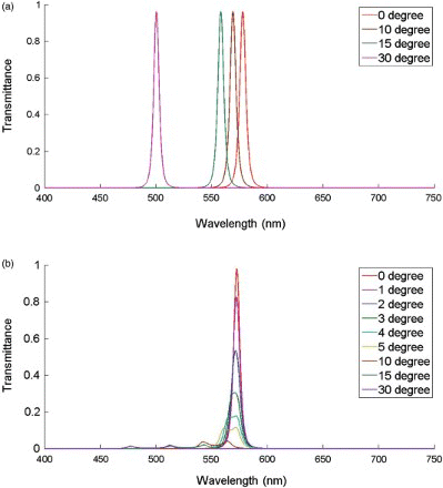
In the solution proposed herein, a high LC birefringence is utilized together with the double-FP-filter structure to compensate for and weaken the blue-shift effect. When the incident angle changes, the average refractive index n of the LC also changes, according to Equation (6). As mentioned in Section 2, the pretilt angles of the proposed double-FP-filter device are intentionally set to be opposite to each other. Thus, the changes in the n1 and n2 of the upper and lower LC interlayers will counteract each other regardless of the symmetry of the incident angle. Without preference, n1 is assumed to increase, and n2 is assumed to decrease, then the phase difference δ1 is compensated for when the incident angle varies within a limited range, and the phase difference δ2 is reduced, resulting in a minimal variation of the transmission spectrum of the upper FP filter within a limited range, and a larger blue shift of the lower FP filter. The high birefringence of the LC will lead to a mismatch of the upper and lower transmission spectra that is big enough to block the light outside a limited incident cone, so that the blue shift will be eliminated in the overall transmission spectrum. The tilt angles of the LC were first simulated under certain applied voltages, then these results were processed according to Equation (6) to obtain the average refractive index n under different incident angles. Finally, the spectral response of the double-FP-filter device was calculated using Equation (1) and is shown in (b).
In , within an incident cone of 30°, the transmission peak of the conventional single-FP-filter device shifts from 572.6 to 495.0 nm. On the other hand, the transmission peaks of the double-FP-filter device with opposite pretilt angles exhibit a minor blue shift despite the fact that the viewing cone is confined. For large-panel applications, a limited viewing cone may be problematic, whereas for mobile applications, this is acceptable as the limited viewing cone can be expanded to some extent through the use of diffusers.
4. Conclusions
In conclusion, proposed herein is an interferometric modulator display with double-layer LC FP filters, which can enable both intensity and wavelength modulations. Its operational principles are elaborated, followed by the presentation of the detailed simulation results. With a unique bisubpixel structure, not only a wider color gamut but also a higher resolution can be realized. This type of display is suitable for green-display applications requiring no polarizers and color filters. In particular, it is more advantageous for small mobile panels, where the viewing angle will not be the primary concern.
Funding
This work was sponsored by 973 Program (2013CB328804), the National Natural Science Foundation of China (61307028), and the Science & Technology Commission of the Shanghai Municipality (11JC1405300&13ZR1420000).
References
- C.P. Chen, J.H. Lee, T.-H. Yoon, and J.C. Kim, Opt. Lett. 34, 2222–2224 (2009). doi: 10.1364/OL.34.002222
- H.-P.D. Shieh, Y.-P. Huang, F.-C. Lin, H.-M. P. Chen and Y.-K. Cheng , SID Symp. Dig. 40, 228–231 (2009). doi: 10.1889/1.3256748
- D.J. Broer, L. Lub and G.N. Mol, Nature 378, 467–469 (1995). doi: 10.1038/378467a0
- C.-H. Chen, F.-C. Lin, Y.-T. Hsu, Y.-P. Huang and H.-P.D. Shieh, J. Disp. Technol. 5, 34–39 (2009). doi: 10.1109/JDT.2008.2001578
- Y.-P. Huang, F.-C. Lin and H.-P.D. Shieh, J. Disp. Technol. 7, 630–632 (2011). doi: 10.1109/JDT.2011.2166056
- M.W. Miles, J. SID 5, 379–382 (1997).
- T. Liu and M. O'Neill, Inf. Disp. 24, 26–30 (2008).
- M. Born and E. Wolf, Principles of Optics: Electromagnetic Theory of Propagation, Interference and Diffraction of Light, 7th ed. (Cambridge University Press, Cambridge, 1999).
- S. Gauza, C.-H. Wen, S.-T. Wu, N. Janarthanan and C.-S. Hsu, Jpn. J. Appl. Phys. 43, 7634–7638 (2004). doi: 10.1143/JJAP.43.7634
- C.P. Chen, T.-C. Chung and T.-S. Jen, Phot. Lett. Poland 3, 23–25 (2011).
- N. Ohta and A. Robertson, Colorimetry: Fundamentals and Applications (Wiley, Hoboken, NJ, 2005).