 ?Mathematical formulae have been encoded as MathML and are displayed in this HTML version using MathJax in order to improve their display. Uncheck the box to turn MathJax off. This feature requires Javascript. Click on a formula to zoom.
Abstract
Two bottom-up methods based on the turbulence closure and bulk model were utilised to estimate drag coefficients at high wind speeds based on ocean current and temperature profiles observed by two subsurface buoys during Typhoon Megi in the South China Sea. A numerical experiment was conducted using the turbulence closure model to test the impact of missing measurements in the upper mixed layer on the wind stress estimate and reconstruction of the upper ocean current. The results were sufficiently robust after several time steps. The wind stresses derived from the two methods were consistent with each other. Wind stress increased quickly with increasing wind force, and then was constant. A parametric typhoon wind model was applied to obtain the wind field and estimate the corresponding drag coefficient. The results showed that the drag coefficient increased to a maximum at a critical wind speed of about 30 m s−1, and then levelled off with increasing wind speed. The uncertainty of the maximum drag coefficient was about ±0.5 due to neglect of nonlinear terms, the uncertainty of the model wind speeds and the drag coefficient. The critical wind speed for the maximum drag coefficient varied by at least ±5 m s−1. The uncertainty of the drag coefficient parameterisation was about 24% due to wind speed. These results indicate that a bottom-up method can be used to estimate drag coefficients at the forced stage during the passage of typhoons or hurricanes.
1. Introduction
Accurate estimates of wind stress over the sea surface during high winds are paramount to forecasting the storm track and intensity correctly, as well as accurately predicting storm surges, ocean waves and currents. Conventional methods of determining air–sea momentum transfer originate from the atmospheric boundary layer based on wind profile or turbulent flux measurements near the sea surface, which are top-down methods (Jarosz et al., Citation2007). Wind stress,τ, is generally calculated as:(1)
(1)
where τx and τy are wind stress with respect to the x and y directions, ρa is air density, U10 is wind speed at 10 m above the sea surface and CD is the drag coefficient.
Many field wind stress measurements have been taken at wind speeds <20 m s−1 (Wu, Citation1980; Large and Pond, Citation1981; Geernaert et al., Citation1987; Smith et al., Citation1992; Yelland and Taylor, Citation1996; Toba et al., Citation2001; Edson et al., Citation2007; Petersen and Renfrew, Citation2009). As reported, CD monotonically increases with wind speed, and the drag coefficient is routinely expressed as a linear function of wind speed. Owing to the lack of observations under extreme wind conditions, such as tropical cyclones, hurricanes and typhoons, the monotonic increase in the drag coefficient with wind speed obtained at low to moderate wind speeds (<20 m s−1) has been extrapolated to high wind speeds and deployed in wave, surge and circulation numerical models. However, recent studies show that such an extrapolation may result in overestimation of the air–sea momentum transfer and unrealistic model predictions.
Since the pioneering work of Powell et al. (Citation2003), several laboratory and field measurements have demonstrated a reduction or saturation of the drag coefficient when wind speed is greater than a critical value of 24–40 m s−1 (Donelan et al., Citation2004; French et al., Citation2007; Jarosz et al., Citation2007; Holthuijsen et al., Citation2012; Takagaki et al., Citation2012; Zhao et al., Citation2015). Several studies have attempted to provide physical explanations for the reduction in the drag coefficient at high wind speeds (Andreas, Citation2004; Makin, Citation2005; Kudryavtsev and Makin, Citation2011; Liu et al., Citation2012). However, the behaviour of CD at high wind speeds has been poorly investigated due to the lack of observational data in the field. In fact, it is very difficult to measure the momentum flux directly from the air side near the air–sea interface under high wind conditions, as vigorous wave breaks produce sea spray in the lower atmospheric boundary layer. In this situation, the meteorological observations above the sea surface are not reliable due to significant contamination by water droplets and movement of the instruments. For example, the work of Powell et al. (Citation2003) was based on wind profiles measured in the vicinity of the hurricane eyewalls through GPS sondes dropped from aircraft at altitudes of 1.5–3 km. Some studies have suggested that estimates of air–sea momentum flux can be determined from observations of the wind-driven ocean current profiles through a bottom-up method (Yu and O’Brien, Citation1991; Jarosz et al., Citation2007). Yu and O’Brien (Citation1991) estimated the drag coefficient and vertical distribution of eddy viscosity from observations of ocean current profiles in the north-western Sargasso Sea using a variational optimal control technique with a modified Ekman layer model. By integrating the momentum equation with the observed ocean current profile, Jarosz et al. (Citation2007) used a bulk method to determine wind stress in the Gulf of Mexico. These studies indicate that a bottom-up method can be applied to estimate drag coefficients using observations of ocean current profiles.
Following the approach mentioned above, two bottom-up methods were applied to estimate wind stresses and drag coefficients through the observed ocean current and temperature profiles during Typhoon Megi, which passed two mooring subsurface buoys in the northern South China Sea (SCS) in October 2010. As part of the South China Sea Internal Wave Experiment (Guan et al. Citation2014), Ocean University of China deployed mooring subsurface buoys to record continuous current and temperature profiles. Section 2 will introduce Typhoon Megi, the two mooring subsurface buoys and the corresponding observational data. The two bottom-up methods and a numerical experiment are briefly described in Section 3. The wind stresses and drag coefficients are estimated using the observational data as well as a parametric typhoon model in Section 4. Finally, the conclusions are given in Section 5.
2. Typhoon Megi and observational data
Typhoon Megi was originally generated in the western North Pacific Ocean on 13 October 2010. According to the Joint Typhoon Warning Centre (JTWC), Typhoon Megi gradually reached category 5 on October 17 east of the Philippines, and significantly weakened to category 2 during its passing through the Philippines on October 18. After entering the SCS, Typhoon Megi quickly re-intensified to category 4 at 18:00 UTC on October 19, heading toward the northern SCS. Finally, Typhoon Megi made landfall on the southern coast of Fujian Province on October 23. Fortunately, the centre of Typhoon Megi passed through the middle of the two subsurface buoys at 00:00 UTC on October 22, with a distance of about 25 km to the right side subsurface buoy (RSB), and 30 km to the left side subsurface buoy (LSB) (Fig. ). The locations of the RSB and LSB are 118°25.61′E, 21°03.59′N and 117°52.66′E, 21°06.57′N, where water depths were 2,480 m and 968 m, respectively. Both buoys were equipped with upward-looking 75 kHz acoustic Doppler current profilers at a water depth of about 400 m, which measured the current profiles from near the instrument to a water depth of about 40 m with a vertical spatial resolution of 8 m every 3 min. In addition, the RSB was also equipped with a 300 m-long temperature chain capable of measuring the temperature profile from a depth of 60–360 m using 28 thermometers and two CTDs with a vertical spatial resolution of 10 m and a time interval of 1 min (Fig. ). The velocity and temperature data were interpolated into uniform levels at 5 m intervals and averaged every 30 min to produce a time series with 30 min resolution. Last, the effective vertical ranges of velocity and temperature were 50–375 m and 60–360 m, respectively (Guan et al., Citation2014). The results are shown in Fig. .
Fig. 1. The track of Typhoon Megi (black curve) and the locations of the two subsurface buoys (black triangles) to the left (LSB) and right (RSB) sides of the storm track.
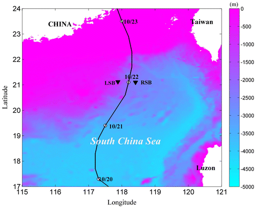
Fig. 2. Sea surface temperature (SST) (a) and the temperature profile (b) varying with time observed at the right side subsurface buoy (RSB). Here, the SSTs between 10/20 and 10/23 are shown in a). The SST for the RSB was read based on the location of the subsurface buoys and it is shown as a top band in b).
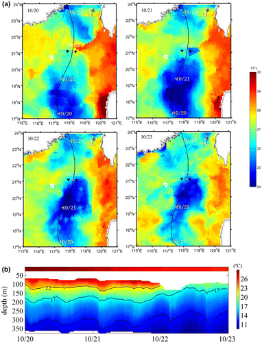
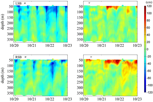
Fig. 3. Ocean current profiles of the eastward and northward components varying with time at the left side subsurface buoy (LSB) and right side subsurface buoy (RSB).
Sea surface temperature (SST) was obtained from Merged Microwave and InfraRed SST daily products (MW_IR SST, available online at www.remss.com). Figure (a) illustrates the variability in SST during the passage of Typhoon Megi, and shows that SST decreased from 28.4 °C on October 20 to 25.2 °C on October 22. The cooler SST was induced by vertical entrainment of colder water upward to the upper ocean, which accordingly led to the isotherms moving upward (Fig. (b)). In the case of RSB, the isotherms were enhanced at around 50 m toward the sea surface.
Before we were able to use the observed current profiles to derive wind stress, the measurement error, high-frequency motion and tidal currents were removed from the observational data. A fourth-order low-pass Butterworth filter with a 6 h cut-off period was deployed twice, once forward and once backward, to minimise phase distortion for the measurement errors and high-frequency motion, following Mitchell et al. (Citation2005), Jarosz et al. (Citation2007) and Teague et al. (Citation2007).
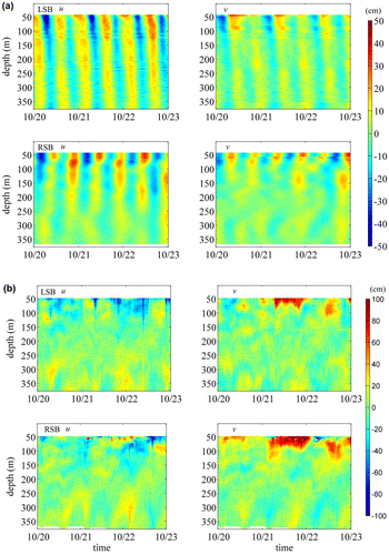
The tidal harmonic coefficients and velocities were computed for the tidal currents using the tidal analysis program T_TIDE (Pawlowicz et al., Citation2002). As shown in Fig. (a), 29 components were distinguished, where semidiurnal and diurnal tides are dominant. After removing the high-frequency motion and tidal currents from the observational data, the resulting current profiles at the LSB and RSB are shown in Fig. (b).
Fig. 4. Contour of the eastward and northward components of the tides (a) and currents after removing tides vs. depth and time (b).
The ocean currents in the upper layer at the RSB were significantly stronger than those at the LSB. This bias behaviour of ocean currents between the right and left sides of the typhoon track has been explained by Price (Citation1981). Owing to the forward movement of the typhoon, the wind stress vector turns clockwise with time on the right side of the track and turns counter-clockwise on the left side of the track. Wind stress and near-inertial current rotate in the same direction on the right side of the track, which leads to a near-resonant coupling to enhance the ocean current. However, the wind stress and wind-driven near-inertial current rotate in opposite directions on the left side of the track, resulting in a reduction of wind-driven near-inertial currents.
3. Turbulence closure and bulk models
3.1. Models
Considering a continuously stratified and horizontally unbounded ocean surface layer with water depth H and the z-axis vertically upwards, and assuming the flow is homogeneous in the horizontal, the rotational hydrodynamic equation and temperature equation can be written as (D’Alessio et al., Citation1998):(2)
(2)
(3)
(3)
(4)
(4)
where u and v are the velocity components with respect to the x and y directions, θ is potential temperature, KM is eddy viscosity, KH is eddy diffusivity, f is the Coriolis parameter, QSR is solar shortwave radiation, ρw is water density and cpw is water heat capacity at constant pressure.
Equations (Equation2–4) are mainly driven by atmospheric forcing at the surface, z = 0. The upper ocean satisfies the following boundary conditions. At the surface, the continuity of wind stress implies:(5)
(5)
(6)
(6)
The surface heating/cooling condition is:(7)
(7)
where Q represents net non-solar heat (i.e. sum of net long-wave radiative, sensible and evaporative heat fluxes) received at the surface and is positive for heating and negative for cooling.
It is clear that the key issue for this model is to determine the eddy viscosity and diffusivity in Equations (Equation5–7). One useful method is to solve the TKE budget equations directly through different turbulence closure schemes. The General Ocean Turbulence Model (GOTM) contains a variety of different turbulence closure schemes, such as an empirical model, energy models and two-equation models (Burchard et al., Citation1999). The commonly used two-equation turbulence closure models in geophysical fluid flow problems are the k–ε (Launder and Spalding, Citation1972; Sasmal et al., Citation2015) and k–kl (Mellor and Yamada, Citation1982) models. They are widely used for the mixed layers of the ocean and atmosphere and in various engineering and geophysical flow situations. In this study, the GOTM with the k–kl closure scheme was utilised to simulate ocean currents at the LSB and RSB locations in the SCS. Wind stress was determined through an iteration technique by minimising the differences in the current and temperature profiles between the model and observations.
Yu and O’Brien (Citation1991) assimilated the observational current velocity profile data into Equations (Equation2(2)
(2) ) and (Equation3
(3)
(3) ) using the optimal variation technique. By minimising the cost function, which measures the difference between the model results and observational data, the unknown boundary condition, namely, wind stress or drag coefficient, and the vertical eddy viscosity distribution are derived from the observational data. The optimal variation method does not require temperature profile data, but the computation is relatively complex. Yu and O’Brien (Citation1991) reported that the variational optimal method is useful to estimate drag coefficients.
Jarosz et al. (Citation2007) vertically integrated Equations (Equation2(2)
(2) ) and (Equation3
(3)
(3) ) from the sea surface to the sea bottom to eliminate the eddy viscosity estimate and suggested that the momentum equation can be written as:
(8)
(8)
(9)
(9)
where U and V are the depth-integrated velocity components in the x and y directions and τb is friction at the bottom of the sea. Jarosz et al. (Citation2007) obtained the drag coefficients at high wind speeds from Equations (Equation8(8)
(8) ) and (Equation9
(9)
(9) ) by using their observed current velocity profiles from the subsurface buoys in the Gulf of Mexico and assuming a parametric expression for bottom friction. The advantage of this bulk method is that eddy viscosities do not need to be determined explicitly. This bulk method was also applied to estimate wind stress in this study.
3.2. Numerical experiment
As our observational current and temperature data were constrained between water depths of 50 and 375 m, we lack data from the sea surface to a depth of 50 m. Therefore, it must be confirmed in advance by numerical simulation that GOTM performs well in the case of some missing current information within the mixed layer. In this section, we tested the GOTM model to retrieve the correct wind stresses in the case of the missing upper layer data. The GOTM model was evaluated comprehensively using various wind stresses.
In the numerical experiment, water depth was set to 300 m with vertical grid spacing of 5 m and a time step of 1 s. The Coriolis parameter, f, was 5.23 × 10⁻⁵ rad s−1, corresponding to the latitude of the RSB. The initial conditions were as follows: SST of 24 °C, which uniformly decreased by 0.02°C/m with depth, and the current profiles and heat flux were set to zero. Therefore, only the turbulent mixing induced by shear instability was considered, which is similar to the circumstances at high wind speeds. The wind stress applied was increased from 1 to 3 N/m2 to simulate an actual situation in which the wind is unsteady, corresponding to winds of 20–30 m s−1.
The current profiles at the 30 min output intervals from the GOTM were taken as target current profiles (TCPs). The TCPs from the sea surface to depths of 20, 40, 60 and 80 m were removed to simulate the observed current profiles (OCPs).
The optimal steps of the variation technique using OCPs to derive wind stress are:
| (1) | OCP at time 1 was taken as the initial current to input into the GOTM; an estimate of wind stress was given at the same time. | ||||
| (2) | After GOTM was run for 30 min, the simulated current profiles (SCPs) were outputted from the GOTM, and the bias between SCPs and OCPs at time 2 was computed. | ||||
| (3) | Wind stress was changed to make the bias reach the set criterion (10−2) at time 2. This step usually requires iteration, depending on the wind stress estimate. | ||||
| (4) | The current profile output from the GOTM at time 2 was considered the initial current to input into the GOTM, and iterations were used to find wind stress so the SCPs were similar to the OCPs at time 3. | ||||
| (5) | Repeat the above step 1 to 4 again and again, then obtained the following wind stresses from GOTM. | ||||
Figure shows the relative error between the model result and the OCP changing with depth and time. From the top to the bottom subfigures, the TCP information was removed above depths of 20, 40, 60 and 80 m, respectively.
Fig. 5. Current profiles for the numerical experiment. From top to bottom, the information in target current profiles (TCPs) is discarded above depths of 20, 40, 60 and 80 m, respectively. The numbers in the horizontal coordinate show the results at different moments of given TCPs. The solid, dashed and dotted curves are denoted as the TCPs, first simulated current profiles (SCPs) and final SCPs, respectively. The solid arrows and dashed arrows in the upper part of the subfigures are the “observed” and simulated wind stresses.
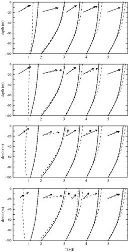
The first SCP (dashed line) largely deviated from the TCP at time 1, when using the wind stress estimate. After several iterations, the relationship improved: the final SCPs (solid line) and TCPs (dotted line) almost overlapped. However, the simulated wind stresses (dashed arrows) deviated from the ‘observed’ wind stress (solid arrows). The more information that is missing, the greater the deviations. At time 2, the initial velocity profile was taken as the final SCP of time 1. It is clear that the deviation from TCPs was reduced compared to that of time 1. The same situation occurred for the ‘observed’ and simulated wind stresses. After repeating step 4 three times at time 5, the simulated results for the velocity profile and wind stress were almost the same as the ‘observed’ ones. Therefore, the GOTM model has the ability to restore the actual situation under the condition of missing mixed layer information.
4. Results and discussion
4.1. Estimate of wind stress
The oceanic response to a typhoon is typically separated into the forced stage and the relaxation stage. During the forced stage, the ocean currents respond significantly to the strong wind force. As pointed out by Price et al. (Citation1994), the ocean response to a very strong wind stress is mainly baroclinic during the forced stage corresponding to the actual storm passage, which induces mixed-layer currents and substantial cooling of the mixed layer and sea surface by vertical mixing. In this situation, the locally generated inertial currents dominated the upper oceanic layer at the observational sites and the background currents were relatively small. The relaxation stage corresponded to the oceanic response after passage of the typhoon. It is an inherently nonlocal baroclinic response to the stress curl of the typhoon. The energy of the wind-driven mixed-layer currents was dispersed in a spreading wake of near-inertial frequency internal waves that penetrated the thermocline, eventually leaving behind a baroclinic current along the storm track (Gill, Citation1984; Price et al., Citation1994).
According to the typhoon track and the location of the subsurface buoys, wind forcing began to increase significantly on October 20 and reached a maximum on October 21. The coincident currents near the sea surface were also greatly enhanced at the LSB and RSB. This period of time corresponded to the forced stage. As mentioned above, bottom-up methods can be applied to the forced stage of the typhoon when the ocean currents are remarkably affected by strong wind stress. Therefore, the simulation was conducted for the time period from 00:00 to 17:00 UTC on October 21 to estimate wind stress from the observational data.
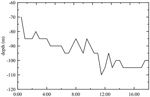
Figure illustrates the corresponding depths of the mixed layer at the RSB varying with time. The depth of the mixed layer was determined by the temperature difference equal to 0.5 °C from the SST. Fig. shows that the depth of the mixed layer decreased continuously during this time, which indicates the forced stage of the typhoon.
At this stage, both the turbulence closure GOTM model and the bulk model were applied to estimate the wind stress in the SCS. The GOTM model used the same water depth, time step and latitude as the idealised experiment. As the temperature profile information is only available at RSB, the GOTM model is only applied at the RSB to estimate the wind stress and drag coefficients. The initial velocity and temperature profiles are taken from the RSB observational data. Owing to the lack of observational data, the initial velocity profile above a depth of 50 m was set to 0, the temperature profile above a depth of 50 m was linearly interpolated using the satellite SST and observational temperature at the RSB, and the initial estimate for momentum flux was 0 N/m2. The observational data at 22:00 UTC on October 20 were taken as the initial condition and the procedure ran continuously for 1 day, corresponding to the forced stage during Typhoon Megi’s pass through the RSB. Wind stress was derived by minimising the difference between SCPs and OCPs.
Following Jarosz et al. (Citation2007), the bulk method can also be used to estimate wind stress. The current velocities at a depth of 0–50 m were taken as the velocity at 50 m. The current profile was integrated from water depths of 0–350 m. It is reasonable to assume that bottom friction is zero. Therefore, from Equations (Equation8(8)
(8) ) and (Equation9
(9)
(9) ), the wind stress was estimated by:
(10)
(10)
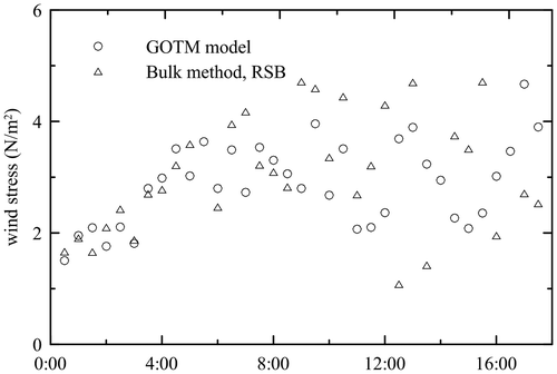
Figure shows the wind stresses estimated by the GOTM and bulk models at the RSB. Wind stress increased continuously and consistently before 8:00 UTC, and then it stopped increasing and varied considerably. The wind stress did not intensify consistently from low to high wind speed, indicating that the drag coefficient decreases at high wind speeds. This result is independent of the exact magnitude of the wind speed. The same behaviour was also found when using the bulk model at the LSB.
Fig. 7. The wind stresses by the General Ocean Turbulence Model (GOTM) and bulk method vs. time (UTC) at the right side subsurface buoy (RSB).
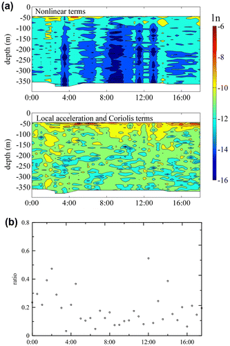
The nonlinear terms were omitted from Equations (Equation2–4) before further calculating the drag coefficient, which may have resulted in an estimate error. The same situation also occurred in the study of Jarosz et al. (Citation2007). The three nonlinear terms, including u ∂ (u, v)/ ∂ x + v ∂ (u, v)/ ∂ y + w(u, v)/ ∂ z, were evaluated as follows. According to the locations of the subsurface buoys, RSB and LSB are nearly in the same latitude; thus, the first term, the eastward component of horizontal advection, u ∂ (u, v)/ ∂ x, can be directly estimated from the observational data of the two buoys. For the northward component of horizontal advection, v ∂ (u, v)/ ∂ y, it is generally reasonable to assume that it is comparable with the first term. To evaluate the third term, w (u, v)/ ∂ z, the vertical velocity, w, was calculated as the time derivative of the vertical displacement of the isotherm, which was measured by the temperature chain equipped in the RSB.
Figure (a) shows the amplitudes of the nonlinear, local acceleration and Coriolis terms that changed with time during October 21. Fig. (b) illustrates the ratios of the nonlinear terms to local acceleration and the Coriolis terms. Most of the ratios were < 0.2, indicating that the one-dimensional model can be roughly used for deriving wind stress.
4.2. Estimate of wind speed
Wind speeds must be obtained to estimate drag coefficients from wind stresses. In this study, a parametric model by Holland et al. (Citation2010) was applied to construct the typhoon wind field combined with the JTWC data (available online at http://www.usno.navy.mil/JTWC). The data download from JTWC contained the basin, time, location (latitude and longitude), maximum wind speed and its corresponding radius, wind speeds at radii of 35, 50, 65 and 100 kts, central pressure and pressure and radius of the last closed isobar. According to Holland et al. (Citation2010), the wind speed at a height of 10 m above the sea surface is derived from:(11)
(11)
where r is the radius of the wind and rm is the radius corresponding to maximum wind U10m. The exponent bs is a scaling parameter that defines the proportion of the pressure gradient near the maximum wind radius:(12)
(12)
where ρs is surface air density, e is the base of natural logarithms, pcs is central pressure and pns is a defined external pressure. The exponent α is a scaling parameter that adjusts the profile shape:(13)
(13)
where αn is a scaling parameter α corresponding to the peripheral observations at radius rn. The parameters bs and αn must be obtained first before determining the wind speed. The parameter bs was calculated by inputting maximum wind speed, central pressure and pressure at the radii of the last closed isobar into Equation (Equation12(12)
(12) ). αn was determined using wind speed at the radii defined at 35, 50, 65 or 100 kts. In this study, αn was determined by the average of α35, α50, α65 and α100, which are calculated by respectively inputting wind speeds at the radii of 35, 50, 65 and 100 kts into Equation (Equation11
(11)
(11) ) with bs estimated from Equation (Equation12
(12)
(12) ). The wind field can be calculated with bs and αn using Equation (Equation11
(11)
(11) ). Following the method of Guo and Sheng (Citation2015), the translational velocity of the typhoon was also added to the typhoon wind field.
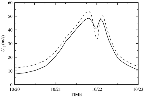
Figure shows the variation in wind speed with time from October 20 to October 23 at the RSB and LSB. Wind speed increased sharply on October 21, and the eye of the typhoon crossed in the middle of the RSB and LSB at midnight with a translation speed of 2.95 ms−1. Maximum wind speed was 50 ms−1.
Fig. 9. Wind speeds varying with time from October 20 to October 23 at the right side subsurface buoy (dashed line) and the left side subsurface buoy (solid line).
Wind speed, U10, was not a directly measured quantity but obtained from a parametric typhoon wind model, which depends on the parameters U10m and rm. According to Landsea and Franklin (Citation2013), the uncertainty of U10m is about ( 5 ms−1 compared with satellite and aircraft data, whereas rm was normally unobtainable before the satellite era. We considered that U10m and rm, varied at ( 5 ms−1 and ±5 km, respectively, to analyse the uncertainty in U10. The uncertainties in U10 generated by U10 m and rm were ±3.5 and ±2.5 ms−1, respectively. Uncertainty decreases with the distance between the typhoon centre and the subsurface buoys. Total uncertainty of U10 was about ± 5 ms−1 after considering the uncertainty of both U10 m and rm.
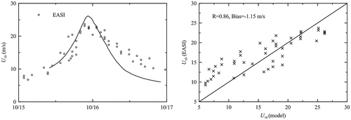
We also validated the wind models with observations from the Impact of Typhoons project on the Ocean in the Pacific (ITOP) experiment that took place during August–November 2010 in the Philippine Sea, east of Taiwan (D’Asaro et al., Citation2014; Drennan et al., Citation2014). Three typhoons were observed during the ITOP program, including Typhoon Megi. A specially designed extreme air–sea interaction (EASI) buoy was deployed to measure winds and waves locally, in which maximum 30 min winds at the buoys reached 26 ms−1, and maximum wave heights over 10 m were recorded (Drennan et al., Citation2014). Figure shows a comparison of model wind speeds with those observed by EASI on October 15 and 16. The model and observed wind speeds were generally consistent with each other with a correlation coefficient of 0.86 and mean bias of −1.15 ms−1. Therefore, the wind field model was applied to calculate the drag coefficients further.
4.3. Drag coefficient and its parameterisation
The drag coefficient was calculated using Equation (Equation1(1)
(1) ) and the wind stress and wind speed were obtained as described above. Figure shows the results derived from the GOTM and bulk model at the RSB and LSB. The drag coefficients were relatively similar to each other despite the high scatter. The standard deviations are also illustrated in Fig. with a bin average over 2 ms−1. The drag coefficients levelled off at wind speeds of 29–32 ms−1.
Fig. 11. Drag coefficient vs. wind speed calculated from the General Ocean Turbulence Model (GOTM) and bulk models. Error bars show ± 1 standard deviation from the bin averaged over 2 ms−1.
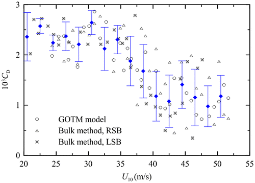
Based on the wind stress errors induced by nonlinear terms and wind speed induced by the model winds, the total uncertainty of the drag coefficients was comprehensively estimated. Fig. gives the mean drag coefficient values with uncertainties (vertical bar). It can be seen that the uncertainties roughly increase with wind speed, and the largest uncertainty is about ±0.5. Figure includes the observational data of Jarosz et al. (Citation2007), who also derived data from subsurface buoys using the bulk method. The field observational data of Powell et al. (Citation2003) and Holthuijsen et al. (Citation2012) are illustrated for comparison. Considering the uncertainties of the observational data, it is clear that our results are consistent with previous studies. Combining the four data sets, the best fit was expressed by a second-order polynomial (solid curve in Fig. ).(14)
(14)
Fig. 12. Parameterisation of the drag coefficients obtained by Powell et al. (2003), Holthuijsen et al. (2012), and Jarosz et al. (2007) corresponding to the resistance coefficient 0.001 cm s−1 and our study denoted by error bars. The shadow shows the uncertainties in the drag coefficient parameterisation due to wind speed.
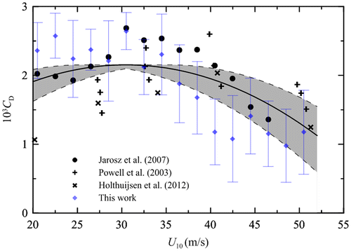
The estimated uncertainty of Equation (Equation14(14)
(14) ) was about 24% as a whole after considering the uncertainty of wind speed. It is clear that Equation (Equation14
(14)
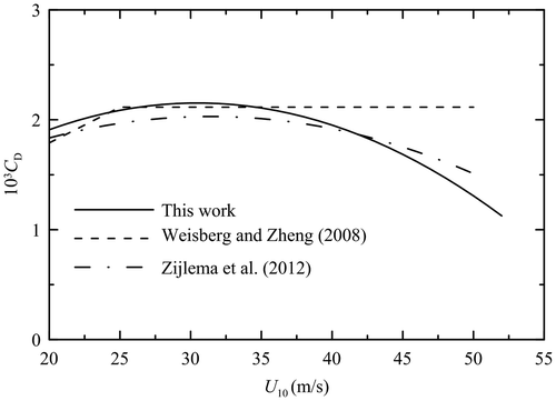
(14) ) is valid for wind speeds of 20–50 ms−1, in which CD attains its maximum value of 2.02 × 10⁻³ at a wind speed of 29.5 ms−1.
To parameterise the decrease in the drag coefficient at high wind speeds, Weisberg and Zheng (Citation2008) simply modified the CD parameterisation proposed by Large and Pond (Citation1981) by setting CD constant at 2.115 × 10⁻³ when wind speed is > 25 ms−1. Zijlema et al. (Citation2012) averaged nine authoritative data sets over 2 ms−1 wind speed bins (see their Fig. ). Based on these data, they fitted CD as a second-order polynomial, in which CD attained its maximum at a wind speed of 31.5 ms−1. This parameterisation is adopted by the SWAN wave model. Figure shows a comparison of Equation (Equation14(14)
(14) ) with the CD parameterisations of Weisberg and Zheng (Citation2008) and Zijlema et al. (Citation2012). Figure shows that the three parameterisations are roughly consistent at wind speeds < 40 ms−1.
Fig. 13. Comparison of the drag coefficient (CD) parameterisations using Equation (Equation14(14)
(14) ), Weisberg and Zheng (Citation2008) and Zijlema et al. (Citation2012).
This study shows a roll-off of CD at a critical wind speed of about 30 ms−1, which is almost the same as that of Jarosz et al. (Citation2007). Powell et al. (Citation2003) and Donelan et al. (Citation2004) determined that CD reaches its maximum at a wind speed of 33 ms−1. French et al. (Citation2007) found a roll-off at a much lower wind speed of about 21 ms−1 using direct observations from an aircraft, although they claimed to remain uncertain. A similar result obtained by Potter et al. (Citation2015) showed evidence of a roll-off CD at a wind speed of 22 ms−1 with the direct buoy observations in typhoons. Based on the wind profile measured from a tower, Zhao et al. (Citation2015) revealed that CD begins to decrease at wind speeds of 24 ms−1. However, with the high-resolution wind profiles collected with GPS drop sondes, Holthuijsen et al. (Citation2012) reported that CD begins to decrease at a wind speed of about 40 ms−1, which is much greater than those of French et al. (Citation2007), Potter et al. (Citation2015) and Zhao et al. (Citation2015). It is clear that the critical wind speeds for maximum CD need to be investigated further.
In addition to wind speed, the drag coefficient also depends on other factors. In fact, the drag coefficient, CD, represents sea surface roughness, which is mainly ascribed to the effect of wind waves and swells. Therefore, instead of wind speed, the drag coefficient is directly related to ocean waves and their breaking, especially under typhoon conditions. For example, Holthuijsen et al. (Citation2012) showed that the wind speed dependence of CD varies spatially around a tropical cyclone in response to sea state caused by wind–swell interactions. In the case of cross swell, they found that CD increases considerably compared with the situation of no or opposing and following swells. In addition, Liu et al. (Citation2012) suggested that CD depends on the development of wind waves during high winds. Holthuijsen et al. (Citation2012) also emphasised the significant effect of wave breaking on CD. At very high wind speeds, a whitecap is blown off the crest in a layer of spray droplets, and the air–sea interface forms a foam, spray and bubble emulsion layer. Such evolution of the sea surface affects the drag coefficient. Holthuijsen et al. (Citation2012) indicated that the mechanism of roll-off of CD is due to the streaks merging into white out and a high-velocity surface jet developing. Owing to the lack of comprehensive observational data, most studies have focused on the dependence of the drag coefficient on wind speed, which is only a proxy for ocean waves. The same situation also occurs under low and moderate wind conditions.
5. Concluding remarks
It is unknown how the momentum transfer from wind stress on the surface from the air side splits between wave growth and current generation on the water side. Many studies have shown that almost all momentum input for wave growth is dissipated by waves breaking. At most, 10% of the wind input is used for wave growth (Mitsuyasu, Citation1985; Terray et al., Citation1996). Much of the momentum transferred from the wind to waves is lost by wave breaking and is delivered to currents. Bottom-up methods estimate the momentum transferred across the sea surface via ‘skin friction’ coupled with momentum input from wave dissipation. Thus, the results can be used to represent total wind stress with a slight underestimate.
Typhoon Megi passed through the middle of two subsurface buoys in the SCS in October 2010, which provided us with an opportunity to study the drag coefficient under strong wind conditions. Based on the observational data of the ocean current and temperature profiles, two bottom-up methods, GOTM and the bulk model, were applied to estimate wind stress under typhoon wind conditions.
The results show that the wind stresses derived from the GOTM and the bulk model were consistent with each other. As wind forcing increased, wind stresses intensified continuously with time and became constant. Notably, this result is independent of wind speed magnitude. A parametric typhoon wind model proposed by Holland et al. (Citation2010) was adopted to obtain the wind field, and drag coefficients were derived accordingly. The drag coefficients increased up to a maximum and then decreased with increasing wind speed. Combined with previous observational data, a new parameterisation of the drag coefficient with a maximum at a critical wind speed of 29.5 ms−1 is proposed.
We have also analysed the error estimate due to the neglect of the nonlinear terms, uncertainty in model wind speeds and the drag coefficient. A final estimate of the uncertainty in the drag coefficient was calculated after combining these factors. The total uncertainty in CD at maximum wind speed was about ±0.5, and the critical wind speed varied at least ±5 ms−1. This issue remains to be investigated in the future. These results indicate that a bottom-up method can be applied to estimate wind stress and the drag coefficient during the forced stage of typhoons and hurricanes, in which the oceanic response to a typhoon is dominated by inertial motion affected by strong wind stress.
Disclosure statement
No potential conflict of interest was reported by the authors.
Funding
This work was supported by the Public Science and Technology Research Funds Projects of Oceans [grant number 2014CB745000]; the Major State Basic Research Development Program of China (973 Program) [grant number 20120132110004]; the National Natural Science Foundation of China [grant number 41276015]; the Strategic Priority Research Program of the Chinese Academy of Sciences [grant number XDA11010403]; the Joint Project for the National Oceanographic Centre by the NSFC and Shandong Government [grant number U1406401]; and the Doctoral Fund of the Ministry of Education of China [grant number 201505007].
Acknowledgements
The authors are grateful to Ms. Dianna Francisco for the English proofreading. The efforts of the researchers who obtained and published the data adopted in this study as well as their funding organisations are much appreciated. The observational data read from the corresponding published papers are available from Dongliang Zhao through e-mail: [email protected].
References
- Andreas, E. L. 2004. Spray stress revisited. J. Phys. Oceanogr. 34, 1429–1440.10.1175/1520-0485(2004)034<1429:SSR>2.0.CO;2
- Burchard, H., Bolding, K. and M. R. Villarreal. 1999. GOTM, a general ocean turbulence model: theory, implementation and test cases. Tech. Rep. EUR 18745, Euro Comm.
- D’Alessio, S. J. D., Abdella, K. and McFarlane, N. A. 1998. A new second–order turbulence closure scheme for modeling the oceanic mixed layer. J. Phys. Oceanogr. 28, 1624–1641.10.1175/1520-0485(1998)028<1624:ANSOTC>2.0.CO;2
- D’Asaro, E. A., Black, P. G., Centurioni, L. R., Chang, Y.-T., Chen, S. S. and co-authors. 2014. Impact of typhoons on the ocean in the Pacific. Bull. Am. Meteorol. Soc. 95, 1405–1418. DOI:10.1175/BAMS-D-12-00104.1.
- Donelan, M. A., Haus, B. K., Reul, N., Plant, W. J., Stiassnie, M., and co-authors. 2004. On the limiting aerodynamic roughness of the ocean in very strong winds. Geophys. Res. Lett. 31, 102. DOI:10.1029/2004GL019460.
- Drennan, W. M., Graber, H. C., Collins, C. O. III, Herrera, A., Potter, H. and co-authors. 2014. EASI: An air–sea interaction buoy for high winds. J. Atmos. Oceanic Technol. 31, 1397–1409. DOI:10.1175/JTECH-D-13-00201.1.
- Edson, J. B., Crawford, T., Crescenti, J., Farrar, T., French, J., and Co-authors. 2007. The coupled boundary layers and air–sea transfer experiment in low winds (CBLAST–Low). Bull. Am. Meteorol. Soc. 88, 342–356.
- French, J. R., Drennan, W. M., Zhang, J. A. and Black, P. G. 2007. Turbulent fluxes in the Hurricane boundary layer. Part I: Momentum flux. J. Atmos. Sci. 64, 1089–1102.10.1175/JAS3887.1
- Geernaert, G. L., Larsen, S. E. and Hansen, F. 1987. Measurements of the wind stress, heat flux, and turbulence intensity during storm conditions over the North Sea. J. Geophys. Res. 92(C12), 13127–13139.10.1029/JC092iC12p13127
- Gill, A. E. 1984. On the behavior of internal waves in the wakes of storms. J. Phys. Oceanogr. 14, 1129–1151.10.1175/1520-0485(1984)014<1129:OTBOIW>2.0.CO;2
- Guan, S., Zhao, W., Huthnance, J., Tian, J. and Wang, J. 2014. Observed upper ocean response to typhoon Megi (2010) in the Northern South China Sea. J. Geophys. Res. Oceans 119, 3134–3157. DOI:10.1002/2013JC009661.
- Guo, L. and Sheng, J. 2015. Statistical estimation of extreme ocean waves over the eastern Canadian shelf from 30-year numerical wave simulation. Ocean Dyn. 65, 1489–1507.10.1007/s10236-015-0878-y
- Holland, G. J., Belanger, J. I. and Fritz, A. 2010. A revised model for radial profiles of hurricane winds. Mon. Weather Rev. 138(12), 4393–4401.10.1175/2010MWR3317.1
- Holthuijsen, L. H., Powell, M. D. and Pietrzak, J. D. 2012. Wind and waves in extreme hurricanes. J. Geophys. Res. 117, C09003. DOI:10.1029/2012JC007983.
- Jarosz, E., Mitchell, D. A., Wang, D. W. and Teague, W. J. 2007. Bottom–up determination of air–sea momentum exchange under a major tropical cyclone. Science 315, 1707–1709.10.1126/science.1136466
- Kudryavtsev, V. N. and Makin, V. K. 2011. Impact of ocean spray on the dynamics of the marine atmospheric boundary layer. Bound.-Layer Meteor. 140(3), 383–410.10.1007/s10546-011-9624-2
- Large, W. G. and Pond, S. 1981. Open ocean momentum flux measurements in moderate to strong winds. J. Phys. Oceanogr. 11, 324–336.10.1175/1520-0485(1981)011<0324:OOMFMI>2.0.CO;2
- Launder, B. E. and Spalding, D. B. 1972. Lectures in Mathematical Models of Turbulence Academic Press, London, p. 169.
- Landsea, C. W. and Franklin, J. L. 2013. Atlantic hurricane database uncertainty and presentation of a new database format. Mon. Weather Rev. 141(10), 3576–3592.10.1175/MWR-D-12-00254.1
- Liu, B., Guan, C. and Xie, L. 2012. The wave state and sea spray related parameterization of wind stress applicable to from low to extreme winds. J. Geophys. Res. 117, C00J22. DOI: 10.1029/2011JC007786.
- Makin, V. K. 2005. A note on the drag of the sea surface at hurricane winds. Bound.-Layer Meteor. 115, 169–176.10.1007/s10546-004-3647-x
- Mellor, G. L. and Yamada, T. 1982. Development of a turbulence closure model for geophysical fluid problems. Rev. Geophys. Space Phys. 20, 851–875.10.1029/RG020i004p00851
- Mitchell, D. A., Teague, W. J., Jarosz, E. and Wang, D. W. 2005. Observed currents over the outer continental shelf during Hurricane Ivan. Geophys. Res. Lett. 32, 12513. DOI:10.1029/2005GL023014.
- Mitsuyasu, H. 1985. A note on the momentum transfer from wind to waves. J. Geophys. Res. 90, 3343–3345.10.1029/JC090iC02p03343
- Pawlowicz, R., Beardsley, B. and Lentz, S. 2002. Classical tidal harmonic analysis including error estimates in MATLAB using T_TIDE. Computers & Geosciences 28(8), 929–937.10.1016/S0098-3004(02)00013-4
- Petersen, G. N. and Renfrew, I. A. 2009. Aircraft-based observations of air–sea fluxes over Denmark Strait and the Irminger Sea during high wind speed conditions. Quart. J. Roy. Meteor. Soc. 135, 2030–2045.10.1002/(ISSN)1477-870X
- Powell, M. D., Vickery, P. J. and Reinhold, T. A. 2003. Reduced drag coefficient for high wind speeds in tropical cyclones. Nature 422, 279–283.10.1038/nature01481
- Potter, H., Graber, H. C., Williams, N. J., Collins, C. O. III, Ramos, R. J. and co-authors. 2015. In situ measurements of momentum fluxes in typhoons. J. Atmos. Sci. 72(1), 104–118.10.1175/JAS-D-14-0025.1
- Price, J. F. 1981. Upper ocean response to a hurricane. J. Phys. Oceanogr. 11, 153–175.10.1175/1520-0485(1981)011<0153:UORTAH>2.0.CO;2
- Price, J. F., Sanford, T. B. and Forristall, G. Z. 1994. Forced stage response to a moving hurricane. J. Phys. Oceanogr. 24, 233–260.10.1175/1520-0485(1994)024<0233:FSRTAM>2.0.CO;2
- Sasmal, K., Maity, S. and Warrior, H. V. 2015. Modeling of turbulent dissipation and its validation in periodically stratified region in the Liverpool Bay and in the North Sea. Ocean Dyn. 65, 969–988.10.1007/s10236-015-0852-8
- Smith, S. D. Anderson, R. J., Oost, W. A., Kraan, C., Maat, N. and Co-authors. 1992. Sea surface wind stress and drag coefficients: the HEXOS results. Bound.-Layer Meteor. 60, 109–142.10.1007/BF00122064
- Takagaki, N., Komori, S., Suzuki, N., Iwano, K., Kuramoto, T. and co-authors. 2012. Strong correlation between the drag coefficient and the shape of the wind sea spectrum over a broad range of wind speeds. Geophys. Res. Lett. 39, L23604. DOI:10.1029/2012GL053988.
- Teague, W. J., Jarosz, E., Wang, D. W., and Mitchell, D. A. 2007. Observed oceanic response over the upper continental slope and outer shelf during Hurricane Ivan. J. Phys. Oceanogr. 37, 2181–2206.10.1175/JPO3115.1
- Terray, E. A., Donelan, M. A., Agrawal, Y. C., Drennan, W. M., Kahma, K. K. and co-authors. 1996. Estimates of kinetic energy dissipation under breaking waves. J. Phys. Oceanogr. 26, 792–807.10.1175/1520-0485(1996)026<0792:EOKEDU>2.0.CO;2
- Toba, Y., Smith, S. D. and Ebuchi, N. 2001. Historical drag expressions. In: Wind Stress Over the Ocean (eds. I. S. F. Jones and Y. Toba). Univ. Press, Cambridge, pp. 35–53.10.1017/CBO9780511552076
- Weisberg, R. H. and Zheng, L. 2008. Hurricane storm surge simulations comparing three–dimensional with two–dimensional formulations based on an Ivan–like storm over the Tampa Bay, Florida region. J. Geophys. Res. 113, C12001. DOI:10.1029/2008JC005115.
- Wu, J. 1980. Wind-stress coefficients over sea surface near neutral conditions — a revisit. J. Phys. Oceanogr. 10, 727–740.10.1175/1520-0485(1980)010<0727:WSCOSS>2.0.CO;2
- Yelland, M. J. and Taylor, P. K. 1996. Wind stress measurements from the open ocean. J. Phys. Oceanogr. 26, 541–558.10.1175/1520-0485(1996)026<0541:WSMFTO>2.0.CO;2
- Yu, L. and O’Brien, J. J. 1991. Variational estimation of the wind stress drag coefficient and the oceanic eddy viscosity profile. J. Phys. Oceanogr. 21, 709–719.10.1175/1520-0485(1991)021<0709:VEOTWS>2.0.CO;2
- Zhao, Z.-K., Liu, C.-X., Li, Q., Dai, G.-F., Song, Q.-T. and co-authors. 2015. Typhoon air-sea drag coefficient in coastal regions. J. Geophys. Res. Oceans 120, DOI:10.1002/2014JC010283.
- Zijlema, M., van Vledder, G. P. and Holthuijsen, L. H. 2012. Bottom friction and wind drag for wave models. Coastal Eng. 65, 19–26.10.1016/j.coastaleng.2012.03.002

