
 ?Mathematical formulae have been encoded as MathML and are displayed in this HTML version using MathJax in order to improve their display. Uncheck the box to turn MathJax off. This feature requires Javascript. Click on a formula to zoom.
Abstract
This article analyses the unsteady hydromagnetic free convection flow near impulsive as well as accelerated motion of the infinite vertical porous plate. The governing momentum and energy partial differential equations exhibiting the physics of the flow formation are presented. Using suitable dimensionless parameters, the equations are transformed to their corresponding dimensionless form and solved exactly in the Laplace domain using the well-known Laplace transform technique. However, the Riemann-sum approximation method is used to invert the solution from the Laplace domain to time domain due of the complexity of the solutions obtained in the Laplace domain. The effect of various pertinent parameters such as suction/injection, Hartmann number, Grashof number, and Prandtl number is discussed with the aid of line graphs.
Nomenclature
| = | constant uniform magnetic field | |
| = | specific heat of the fluid at constant pressure | |
| = | acceleration due to gravity | |
| = | Grashof number | |
| = | Hartmann number | |
| = | dimensionless time | |
| = | dimensional time | |
| = | dimensional constant | |
| = | dimensional fluid velocity | |
| ν0= | = | constant velocity in transverse direction |
| = | Prandtl number | |
| = | suction/injection parameter | |
| = | density | |
| = | Laplace parameter, | |
| = | thermal diffusivity | |
| = | electrical conductivity | |
| = | thermal conductivity | |
| = | temperature of the fluid | |
| = | volumetric coefficient of thermal expansion | |
| = | constant heat flux | |
| = | kinematic viscosity | |
| = | skin friction |
1. Introduction
The effect of suction/injection on the boundary-layer control has contributed a significant role in the field of aerodynamic and space science. Shojaefard et al. [Citation1] applied wall suction/injection to regulate fluid flow on the surface of subsonic airplane. Uwanta and Hamza [Citation2] explored the role of suction/injection on transient hydromagnetic convective flow of reactive viscous fluid between vertical porous plates with thermal diffusion. Later, Jha and Apere [Citation3] investigated the hall and ion-slip effects on the unsteady MHD Couette flow in the rotating system with suction/injection. Jena and Mathur [Citation4] examined free convection in the laminar boundary-layer flow of a thermo-micropolar fluid past a vertical flat plate with suction/injection. Devi and Kandasamy [Citation5] studied the effects of chemical reaction, heat and mass transfer on non-linear MHD laminar boundary-layer flow over a wedge with suction or injection. In other related work, the influence of chemical reaction and radiation absorption on the unsteady MHD free convection flow past a semi-infinite vertical permeable moving plate with heat source and suction is examined by Ibrahim et al. [Citation6].
Stokes [Citation7] was one of the first authors to study flow of an incompressible viscous fluid past an impulsively started infinite horizontal flat plate in its own plane. Later, Sahoo and Sahoo [Citation8] studied the hydromagnetic free convection and mass transfer flow past an impulsively started vertical plate through a porous medium by assuming the magnetic lines of force to be fixed relative to the fluid. Jha and Apere [Citation9] discussed the natural convection flow formation of conducting fluid near moving infinite vertical porous plate when the magnetic field is fixed with a moving porous plate or fluid. They concluded that flow formation is enhanced with an increase in the Hartmann number when the magnetic field is fixed relative to the moving porous plate. The effect of the magnetic field on the free-convective flow has been presented by Georgantopoulos et al. [Citation10].
Singh [Citation11] studied the effect of uniform transverse magnetic field on natural convection flow of electrically conducting fluid past an infinite, vertical, porous plate for constant as well as time-dependent motion of the porous plate when the magnetic field is fixed relative to the fluid or moving porous plate. Chandran et al. [Citation12] discussed unsteady hydromagnetic free convection flow due to accelerated motion of infinite vertical plate with imposed heat flux on the plate. In another article, Chandran et al. [Citation13] examined the unsteady hydromagnetic natural convection flow formation due to impulsive as well as accelerated motion of an infinite vertical porous plate with imposed heat flux on the porous plate. Recently, Ellahi et al [Citation14] scrutinized the structural impact of kerosene-Al2O3 nanoliqiud on MHD Poiseuille flow with variable thermal conductivity, while Bhatti et al. [Citation15] further extended the work by creating mathematical modelling of heat and mass transfer effects on MHD peristaltic propulsion of two-phase flow through a Darcy–Brinkman–Forchheimer porous medium. Other related considered literatures can be found in [Citation16–20]. From all the above cited articles, they have yielded less cumbersome governing equations which could be subjected to simple analytical solution procedure, but the closed form solution is still dependent on the nature of the initial and boundary conditions.
The objective of this study is to investigate the role of suction/injection on unsteady hydromagnetic flow near an infinite vertical porous plate subjected to wall heat flux. The dimensionless parameters characterizing the magnetic and buoyancy force for the unsteady flow of electrically conducting fluid when the flow takes place near an infinite vertical porous plate subject to impulsive/accelerated motion as well as heat flux is also considered. It is hoped that the mathematical solutions presented in this article will not only provide useful information for industrial application, but also serve as an improvement to the previous studies.
2. Mathematical analysis
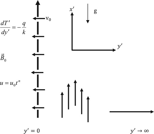
The physical configuration considered is that of the unsteady two-dimensional flow of an incompressible viscous and electrically conducting fluid near an infinite vertical non-conducting porous plate. Taking the along the plate in the vertical direction and the
perpendicular to the plate (see Figure ). A uniform magnetic field
is assumed to be applied in the direction perpendicular to the direction of flow. It is assumed that magnetic Reynolds number is small which corresponds to the negligible induced magnetic field compared to the externally applied one. Initially, the plate and the fluid are at rest and at the same temperature
. Afterward, the porous plate is set into a sudden impulsive or accelerated motion with velocity
in the
direction, where (
) is the time variable and
is a constant having dimension of velocity or acceleration. Simultaneously, heat is also supplied to the plate at a constant rate. As it is common in flow problems past porous plate of the type considered here, it is assumed that the convective and pressure gradients terms in the momentum and energy equations are negligible. Also, as a result of boundary-layer approximations on the flow variable, the physical variables become functions space variable
and time variable
only. To obtain these explicit solutions for two types of boundary motion which are discussed above, namely impulsive and accelerated motions which correspond to
and
, respectively. Using the Boussinesq approximation [Citation21], the governing momentum and energy partial differential equations when the magnetic field is fixed relative to the fluid is written in dimensional form as follows:
(1)
(1)
(2)
(2)
When the magnetic field is fixed relative to the moving boundary with velocity
, the momentum equation (1) takes the form
(3)
(3)
Equations (1) and (3) can be combined into the single equation as
(4)
(4)
where
Equations (2) and (4) are to be supplemented by the initial and boundary conditions
(5)
(5)
The following dimensionless quantities are introduced to obtain the governing equations in dimensionless form:
(6)
(6)
Figure 1. Schematic of the problem.
2.1. Impulsive motion
The dimensionless parameters governing flow formation in the case of impulsive case is obtained by setting in Equation (6)
Using Equation (6), Equations (2) and (4) can be expressed in the dimensionless forms respectively as
(7)
(7)
(8)
(8)
Subject to the initial and boundary conditions:
(9)
(9)
In order to solve Equation (7) subject to the conditions (9), we have to first obtain the temperature distribution from Equation (8). The exact solution in Laplace domain will be obtained using the Laplace transform defined as follows:
(10)
(10)
where
Taking the Laplace transforms of Equations (7) and (8), the equations results to a set of (ordinary) differential equations for the transformed functions in the independent variable . On solving them with the corresponding transformed boundary conditions, we obtain the velocity and temperature distribution in the Laplace domain respectively as follows:
(11)
(11)
(12)
(12)
where
,
,
(13)
(13)
To obtain the velocity and temperature distributions in time domain, Equations (11) and (12) have to be inverted. Since these equations are difficult to be inverted in a closed form, a numerical procedure used in Jha and Apere [Citation22], which is based on the Riemann-sum approximation method, is employed. In this method, any functions in the Laplace domain can be inverted to the time domain
as follows:
(14)
(14)
(15)
(15)
where Re refers to the “real part of”,
is the imaginary number and
is the number of terms used in the Riemann-sum approximation and
is the real part of the Bromwich contour that is used in inverting Laplace transforms. The Riemann-sum approximation for the Laplace inversion involves a single summation for the numerical process. Its accuracy depends on the value of
and his truncation error dictated by
. According to Tzou [Citation23], the value of
must be selected so that the Bromwich contour encloses all the branch points. For faster convergence, the quantity
gives the most satisfactory results.
3. Skin friction
An associated quantity of practical interest in the boundary-layer flow is the skin friction.
The skin friction is obtained by differentiating the velocity with respect to
as follows:
(16)
(16)
The solutions are converted to time domain by applying the Riemann-sum approximation procedure stated in Equation (14).
4. Steady state solution (SSS)
By neglecting the time derivative in Equations (7) and (8) subject to (9) , the steady state (time independent) velocity for impulsive boundary motion and temperature distribution are respectively obtained as
(17)
(17)
(18)
(18)
where
(19)
(19)
4.1. Accelerated motion
In this case at
for
, and the non-dimensional variable governing flow formations are obtained by setting
in Equation (6):
The temperature equation is exactly the same with that of impulsive case, while the momentum equation for the case of accelerated motion of the boundary is given by
(20)
(20)
The solution procedure runs parallel to the case of impulsive motion discussed above and is not repeated for brevity. Considering the boundary condition
at
,
in this case, the velocity profile in the Laplace domain is obtained as
(21)
(21)
which also transforms to time domain by using Equation (14).
5. Results and discussion
In order to have a physical insight into the problem, a MATLAB programme is written to compute and generate graphs for the velocity profile and skin friction for both impulsive and accelerated motions cases. Line graphs of the velocity profiles and skin friction are presented in Figures to reveal the influence of the governing parameters, such as the Hartmann number , suction/injection parameter
, buoyancy force parameter
and dimensionless time
.
Figure 2. Velocity profile showing the effect of for
for impulsive motion
.
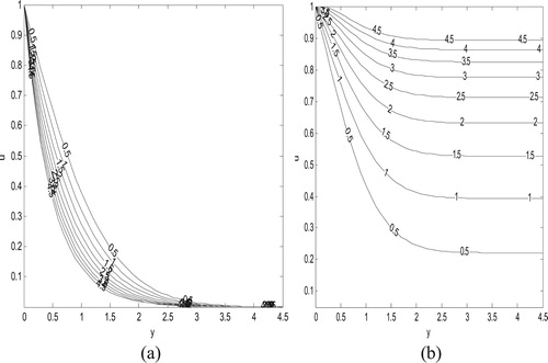
Figure 3. Velocity profile showing the effect of for
for accelerated motion
.
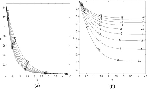
Figure 4. Velocity profile showing the effect of for
for impulsive motion
.
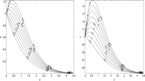
Figure 5. Velocity profile showing the effect of for
for accelerated motion
.
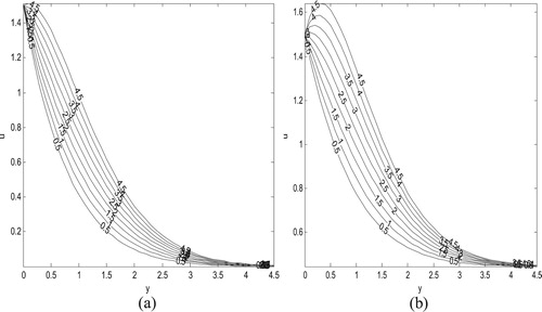
Figure 6. Velocity profile showing the effect of suction/injection parameter for
for impulsive motion
.
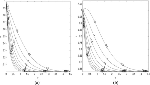
Figure 7. Velocity profile showing the effect of suction/injection parameter for
for accelerated motion
.
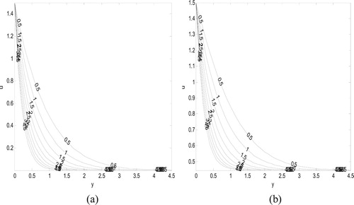
Figure 8. Variation of skin friction versus time for different values of with
for impulsive motion
.
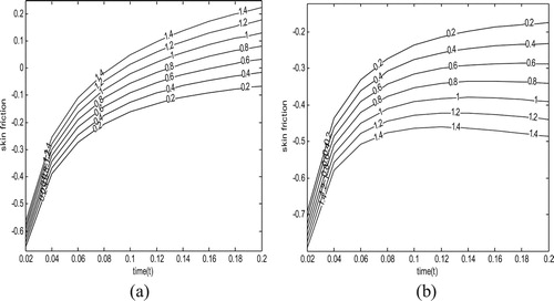
Figure 9. Variation of skin friction versus time for different values of with
for accelerated motion
.
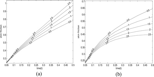
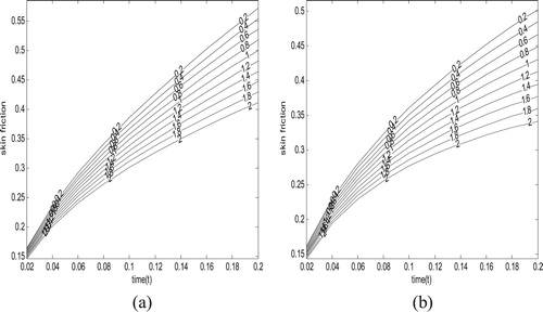
Figure 10. Variation of skin friction versus time for different values of for
for impulsive motion
.
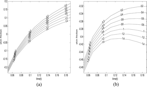
Figure 11. Variation of skin friction versus time for different values of for
for accelerated motion (
.
Figures and exhibit the effect of magnetic field on the fluid velocity for a fixed value of and
. It is noticed that for both impulsive and accelerated cases, velocity increases as the Hartmann number decreases when the magnetic field is fixed relative to the fluid
while a reverse trend is observed when the magnetic field is fixed relative to moving porous plate (
).
Figures and show the variations of buoyancy force parameter at fixed value of and
. From these figures, it is revealed that as the buoyancy force parameter increases, the velocity increases regardless of either impulsive or accelerated motion cases.
Figures and , on the other hand, display impact of suction/injection parameter on fluid velocity. It is found for both impulsive and accelerated motions, respectively, fluid velocity decreases as fluid suction/injection parameter
increases. This can be attributed to transversely impose fluid suction, which tends to distort flow formation in the axial direction. A careful look at these figures indicates a sharp decrease in fluid velocity for the impulsive case compared to the accelerated case.
Figures and exhibit the effect of magnetic field parameter and time on the shear stress both impulsive and accelerated cases, respectively. It is observed that, for both cases, shear stress decreases as the magnetic parameter increases for while a reversal in this trend is noticed for
.
Figures and illustrate the role of buoyancy force and time on shear stress for impulsive and accelerated boundary motions, respectively. It is revealed that for both impulsive and accelerated motion cases respectively regardless of the nature of magnetic field application ( ) shear stress decreases as the buoyancy force increases.
For accuracy check, Tables present numerical comparisons with the published work of Chandran et al. [Citation13] for a non-porous plate . These comparisons give an excellent agreement.
Table 1. Numerical comparison of velocity obtained using the Riemann-sum approximation method and those obtained using the convolution integrals method by Chandran et al. [Citation13] at  , , (impulsive case).
Table 2. Numerical comparison of velocity obtained using the Riemann-sum approximation method and those obtained using the convolution integrals method by Chandran et al. [Citation13] at , , (impulsive case).
Table 3. Numerical comparison of velocity obtained using the Riemann-sum approximation method and those obtained using the convolution integrals method by Chandran et al. [Citation13] at , , (accelerated case).
Table 4. Numerical comparison of velocity obtained using the Riemann-sum approximation method and those obtained using the convolution integrals method by Chandran et al. [Citation13] at , , (accelerated case).
Table 5. Numerical comparison of skin friction obtained using the Riemann-sum approximation method and those obtained using the convolution integrals method by Chandran et al. [Citation13] [impulsive] , , .
Table 6. Numerical comparison of skin friction obtained using the Riemann-sum approximation method and those obtained using the convolution integrals method by Chandran et al. [Citation13] [accelerated case] , , .
6. Conclusion
This study considered the role of fluid suction/injection on magnetohydrodynamic natural convection flow in a vertical plate with impulsive and accelerated motions of the boundary. The mathematical model governing the present physical situation is solved using a combination of the Laplace transform technique and Riemann-sum approximation approach. The main findings are:
As the Hartmann number increases, there is a decrease in the fluid velocity for
Velocity increases with time and finally reaches a steady state situation for impulsive movement of the porous plate.
The shear stress decreases as the Hartmann number increases for
Shear stress increases with time.
Fluid velocity increases as the injection parameter decreases, while shear stress increases as the suction parameter increases.
Disclosure statement
No potential conflict of interest was reported by the authors.
References
- Shojaefard MH, Noorpoor AR, Avanesians A, et al. Numerical investigation of flow control by suction and injection on a subsonic aircraft. Amer J Appl Sci. 2005;20:1474–1480.
- Uwanta IJ, Hamza MM. Effect of suction/injection on unsteady hydrodynamic convective flow of reactive viscous fluid between vertical porous plates with thermal diffusion. Int Sch Res Notices. 2014;14:980270.
- Jha BK, Apere CA. Hall and ion-slip on unsteady MHD Couette flow in a rotating system with suction and injection. J. Phys. Soc. Jpn. 2011;80:114401. doi: 10.1143/JPSJ.80.114401
- Jena SK, Mathur MN. Free convection in the laminar boundary layer flow of a thermomicropolar fluid past a vertical flat plate with suction/injection. Acta Mech. 1982;42:227–238. doi: 10.1007/BF01177194
- Devi SPA, Kandasamy R. Effects of chemical reaction, heat and mass transfer on non-linear MHD laminar boundary-layer flow over a wedge with suction or injection. Int Commun Heat Mass Transfer. 2002;5:707–716. doi: 10.1016/S0735-1933(02)00389-5
- Ibrahim FS, Elaiw AM, Bakr AA. Effect of chemical reaction and radiation absorption on the unsteady MHD free convection flow past a semi-infinite vertical permeable moving plate with heat source and suction. CommunNonlinear Sci Numer Simulation. 2008;13:1056–1066. doi: 10.1016/j.cnsns.2006.09.007
- Stokes G. On the effect of internal friction of fluids on the motion of pendulums. Mathematical and physics papers (1901) reprinted from Trans Cambridge Philos Soc. 1851; 9:(3): 1–141.
- Sahoo DG, Sahoo PK. Hydromagnetic free-convection and mass transform flow past an impulsively started vertical plate through a porous medium. Indian J. Technol. 1986;24:553.
- Jha BK, Apere CA. MHD natural convection flow of fluid of different Prandtl numbers in Stokes problem for a vertical porous plate. J. Phys. Soc. Jpn. 2012;81:064401. doi: 10.1143/JPSJ.81.064401
- Georgantopoulos GA. Effects of free convection on the hydromagnetic accelerated flow past a vertical porous limiting surface. Astrophys. Space Sci. 1979;65:433–441. doi: 10.1007/BF00648508
- Singh AK. MHD free convection flow in Stokes problem for a porous vertical plate. Astrophys Space Sci. 1982;87:455–461. doi: 10.1007/BF00648936
- Chandran P, Sacheti NC, Singh AK. Unsteady hydromagnetic free convection flow with heat flux and accelerated boundary motion. J. Phys. Soc. Jpn. 1989;67:124–129. doi: 10.1143/JPSJ.67.124
- Chandran P, Singh AK, Sacheti NC. A unified approach to analytical solution of a hydromagnetic free convection flow. Sci Math Jpn. 2001;53:467.
- Ellehi R, Zeeshan A, Shehzad N, et al. Structural impact of kerosene-Al2O3 nanoliqiud on MHD Poiseuille flow with variable thermal conductivity: application of cooling process. J Mol Liq. 2018;265:607–615. doi: 10.1016/j.molliq.2018.05.103
- Bhatti MM, Zeeshan A, Ellahi R, et al. Mathematical modelling of heat and mass transfer effects on MHD peristaltic propulsion of two-phase flow through a Darcy-Brinkman-Forchheimer porous medium. Adv Power Technology. 2018;29:1189–1197. doi: 10.1016/j.apt.2018.02.010
- Afsart khan A, Ellahi R, Mudassar Gulzar M, et al. Effect of heat transfer on peristaltic motion of Oldroyd fluid in the presence of inclined magnetic flied 2014. J Magn Magn Mater. 2014;372:97–106. doi: 10.1016/j.jmmm.2014.07.051
- Ellahi R, Khan M, Nehad AS. Combine porous and magnetic effect on some fundamental motions of Newtonian fluids over an infinite plate. J Porous Media. 2018;21(7):589–605. doi: 10.1615/JPorMedia.v21.i7.20
- Zeeshan A, Ijaz N, Abbas T, et al. The sustainable characteristic of bio-bi-phase flow of peristaltic transport of MHD Jeffery fluid in human body. Sustainability. 2018;10(8):2671. doi: 10.3390/su10082671
- Ambreem AK, Fauzia M, Ellahi R, et al. Mass transport on chemicalized fourth-grade fluid propagating through a curved channel with magnetic effects. J Mol Liq. 2018;258:186–195. doi: 10.1016/j.molliq.2018.02.115
- Jha BK, Oni MO. Electromagnetic natural convection flow in a vertical microchannel with joule heating: exact solution. J Taibah Univ Sci. 2018;12:661–668. doi:10.1080/16583655.2018.1494423.
- Jha BK, Oni MO, Aina B. Steady fully developed mixed convection flow in a vertical micro-concentric annulus with heat generating/absorbing fluid: an exact solution. Ain Shams Eng J. Epub Ahead of Print., doi:10.1016/j.asej.2016.08.005.
- Jha BK, Apere CA. Unsteady MHD Couette flow in annuli, The Riemann-Sum approximation approach. J. Phys. Soc. Jpn. 2007;79:124403/1-5.
- Tzou DY. Macro to microscale heat transfer: the lagging behaviour. Washington (DC): Taylor and Francis; 1997.