
 ?Mathematical formulae have been encoded as MathML and are displayed in this HTML version using MathJax in order to improve their display. Uncheck the box to turn MathJax off. This feature requires Javascript. Click on a formula to zoom.
ABSTRACT
The microstructural characteristics and mechanical properties of rotary melting furnace processed aluminium alloyed ductile irons were investigated in this study. This was aimed at developing high performance – low material and processing cost ductile irons, suitable for the production of automobile components. Different compositions of the alloys were processed containing 1–4 wt.% aluminium. X-ray diffractometry, optical, scanning electron microscopy and mechanical properties measurements, were used to characterize the alloys. The results show that the ductile irons consists essentially, nodular and vermicular graphite-type distributed in a predominantly pearlite – ferrite matrix structures which attest to the viability of rotary furnace melt processing for ductile iron production. The nodule count were observed to increase with increase in Al wt.% but nodule sizes and degree of sphericity decreased with increase in Al wt.%. The mechanical properties of the ductile irons increased with increase in Al wt.%, except the ductility which decreased slightly with increase in Al wt.%.
1. Introduction
Ductile iron belongs to the family of cast iron, and in the as-cast condition, the microstructures usually consist of spheroid or vermicular forms of graphite in a pearlite and/or ferrite matrix. Sometimes, the matrix may contain cementite or a combination of these phases. Apart from fundamental factors such as processing technique and cooling rate that dictate would be microstructures and properties [Citation1], addition of some specific important alloying element(s) further improves the performance of ductile irons in service applications.
Ductile irons are traditional materials used in the development of automobile components such as piston rings, exhaust manifolds, disk brake rotor, cylinder linings, camshafts, brake drum; and heat exchangers [Citation2–6]. The increasing demand for more competitive materials which can offer better fuel economy, engine efficiency and overall cost reduction, has challenged the ductile iron community. There is now the need to improve ductile iron metallurgy in order to preserve its relevance as first choice material for several automobile components development.
In recent times, attention has been focused on the addition of aluminium to cast iron for performance enhancement. Apart from being a relatively low-cost metallic material, Al serves as a graphitizer in cast iron and thus helps in the development of carbide free pearlite matrix and high nodules count [Citation7–9]. Al equally, increases the eutectoid temperature of cast irons, thereby increasing the allowable working temperatures [Citation10–12]. The achievement of these microstructural features in cast irons, which are relevant to the improvement of mechanical properties and oxidation and corrosion resistance [Citation13–14], are reported to be dependent on processing factors, and thus the same outcomes are not guaranteed when process factors are altered.
The present study explores the use of rotary melting furnace for the production of Al alloyed ductile irons. Findings from the literature show that induction furnace, vacuum furnace or gas-fired crucible furnace, are principally used for Al alloyed ductile iron production. Very sparse reports exist on the use of rotary furnace for the production of Al alloyed ductile iron. Rotary furnaces are produced locally and are relatively cheaper than most of the conventional furnaces for ductile iron production. Therefore, the aim of this research is to investigate the viability of producing Al low alloyed ductile irons with the use of rotary furnace, with the specific objectives of establishing the effect of rotary furnace processing and Al addition on the microstructure and mechanical properties of ductile irons.
2. Materials and methods
2.1. Materials
The materials used in the research include 72.5% analytical grade of ferro-silicon (FeSi) alloy in both lumps and powders, 5.2% ferro-silicon-magnesium (FeSiMg) alloy, 66% grade of graphite, 98.64% grade of aluminium ingot and engine sleeve scraps of cast iron. The chemical compositions of the engine sleeve cast iron scraps and the alloying additions are presented inTables and .
Table 1. Composition of cast iron sleeve scraps used for the production of the Al alloyed ductile iron (wt%).
Table 2. Composition of the Nodulirizer (MgFeSi), Innoculant (FeSi) and Graphite used for treating ductile iron melt.
2.2. Alloy production
In order to achieve alloys that the chemical composition of the melt will be consistent with the targeted composition, the charge calculation was done using the expression in Equations (1) and (2) which are in accordance with [*Citation15–16,Citation10]. The oxidizing flame that will bring the melt to the required temperature is in direct contact with the charge in the rotary furnace process. This will definitely lead to elemental constituent and high carbon loss during melting. Therefore, consideration was given to that and an appropriate percentage addition was introduced to balance the charge composition [Citation17].
(1)
(1)
(2)
(2)
The Al alloyed ductile cast iron with composition range presented in Table was produced in a 100 kg capacity rotary furnace fired with diesel oil. Six different batches of melt were prepared for the study using sand casting technique. The prepared charge material which was engine sleeve scraps were broken into small pieces and charged into the furnace already pre-heated to 1300°C. The continuous rotation of the furnace ensured even distribution of heat in the furnace and homogenization of the melt. The aluminium ingot was prepared by breaking it into small chips, pre-heated to about 450°C and charged into the ladle alreadycontaining the covered nodularizer. The melt was super-heated to 1727°C, after which it was tapped into the pre-heated ladle that contains both the nodularizer and aluminium chips, and gently stirred for homogenization. This melt practice helped delay the reaction process in the ladle, which prevents fading (burn off) of the magnesium. This was followed by de-slagging of the melt, and subsequently, the nodularized melt was poured at a temperature of about 1350°C into prepared sand moulds. After the casts have cooled, they were removed for fettling and machining to required test specimens specifications.
Table 3. Chemical composition of the alloys produced.
2.3. Chemical analyses of ductile irons
The quantitative measurement of the elemental composition of the ductile iron produced was determined using a model 2000-3 Spetro-CJRO Arc-Spectrometer. The surface of the test sample was prepared by grinding to ensure flatness and mounted on the sparking point of the spectrometer. Each sample was sparked three (3) times and the average value taken. The carbon equivalent values (CEV) of the alloys were obtained using Equation (3).
(3)
(3)
where: C. E is the Carbon Equivalent Value and %C, %Si, %P, %Mn, %S and %Al are the percentages of carbon, silicon, phosphorous, manganese, sulphur and aluminium, respectively that are present in the ductile irons.
2.4. Structural characterization
The microstructures of the ductile irons were examined using a Axio-observer A1 m optical metallurgical microscope equipped with Axio-Cam ERc5 camera for image capturing. Samples were ground and polished successively using emery papers of grades 220, 400, 600, 800, 1000, and 1200 grit size. Final polishing was done on polishing cloth with diamond polish suspension of 3 microns as abrasive. The samples were etched with 2% nital solutions for two minutes before the microstructural examination was embarked on. Further structural analyses of the ductile irons were performed using a JEOL scanning electron microscope (SEM) (a model-JSM 6480LV equipped with energy dispersive spectroscopy EDS), and PW1710 Philips diffractometer with monochromatic Cu target K-α radiation at 40 kV and 45 mA using an high score X’Pert software.
2.5. Mechanical testing
Three tensile samples of gauge length of 28 mm and gauge diameter of 7 mm were prepared for each ductile iron composition, and testing was performed using a table-top universal tensiometer of model KPL 2000–1 with self-aligned Instron 8800 digital controlled panel. The samples were pulled in tension to fracture using a quasi-static strain rate of 10−3/s; and the mean values of the ultimate tensile strength and % elongation determined from the data generated. The specimens preparation, testing procedures and data analysis were all performed in accordance with [*Citation18] standard. Tinius Olsen model JBN-300 capacity impact testing machine with a direct reading gauge was used to determine the impact strength of the ductile irons. Three specimens each of size (10 × 10 × 50) mm with v-notch at the centre at an angle of 45o and a striking load of 75 kg weight were used for testing, and mean values obtained were reported as impact toughness of the ductile irons. The sample specification, testing and analysis of results were in accordance with [*Citation19] specification. Hardness test was conducted to determine micro-hardness values of the ductile irons using a micro-hardness Vickers tester (FALCON 500 series) with diamond indenter under an applied load of 100 gf and dwelling time of 15 s on the polished sample surface. A minimum of five indentations was made for each sample composition and the average value reported as the hardness value. The sample preparations and testing were performed in accordance with [*Citation20,Citation5] standard.
3. Results and discussions
3.1. Chemical composition of the ductile irons
Table presents the results of the spectrographic chemical analyses of the ductile irons produced. For all the compositions, it is observed that they have C.E values above 4.3 which is an indication that the alloys produced should contain hyper-eutectic structure. It is a well-understood phenomenon that higher C.E. values, favour graphite precipitation during cast iron formation on cooling from the liquid state [Citation21], which is necessary for nodules production in ductile irons.
3.2. Microstructural characterization
3.2.1. Microstructural examination
The optical micrographs of the Al alloyed ductile irons produced are presented in Figures . The un-etched micrographs (Figures (a), 2(a), 3(a), 4(a) 5(a) and 6(a) were used to evaluate the graphite type, distribution and nodular counts in accordance with [*Citation22–23] standards. The micrographs show that the chemical composition of the ductile irons influenced the graphite type, sizes and volume of nodules formed. The comparative analyses of the nodule type, counts and distribution as well as the volume fractions of the phases are presented in Table . It is observed from Table that the nodule count increases as the Al wt.% increases. Specifically, the nodules increased from 188 mm-2 for ductile iron composition without aluminium addition to 780 mm-2 for the ductile iron composition containing 3.74 wt.% Al, which is a significant increase in nodule count (∼415%). The increase in nodule count in the Al alloyed ductile iron compositions, is attributable to the graphitizing effect Al has on cast irons. Al addition widens the temperature range of stable and unstable eutectic region, leading to the enhancement of graphitization process [Citation24]. The nodule counts observed in the study are within the range reported in related studies [Citation11,Citation25].
Figure 1. (a) Un-etched optical micrograph of As-cast ductile iron at 20 μm mag. (b) Etched optical micrograph of As-cast ductile iron at 20 μm mag. (2% Nital for 12 s).
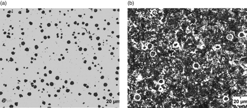
Figure 2. (a) Un-etched optical micrograph of 1.05% Al-ductile iron at 20 μm mag. (b) Etched optical micrograph of 1.05% Al-ductile iron at 20 μm mag. (2% Nital for 12 s).
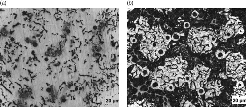
Figure 3. (a) Un-etched optical micrograph of 1.575% Al-ductile iron at 20 μm mag. (b) Etched optical micrograph of 1.575%Al-ductile iron at 20 μm mag. (2% Nital for 12 s).
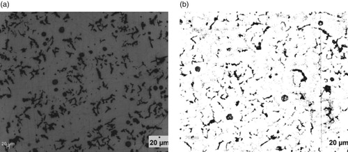
Figure 4. (a) Un-etched optical micrograph of 2.29% Al-ductile iron at 20 μm mag. (b) Etched optical micrograph of 2.29% Al-ductile iron at 20 μm mag. (2% Nital for 12 s).
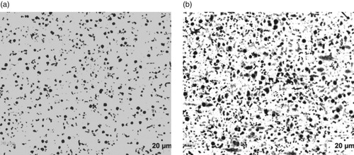
Figure 5. (a) Un-etched optical micrograph of 3.02% Al-ductile iron at 20 μm mag. (b) Etched optical micrograph of 3.02% Al-ductile iron at 20 μm mag. (2% Nital for 12 s).
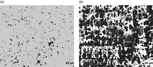
Figure 6. (a) Un-etched optical micrograph of 3.74% Al-ductile iron at 20 μm mag. (b) Etched optical micrograph of 3.74% Al-ductile iron at 20 μm mag. (2% Nital for 12 s).
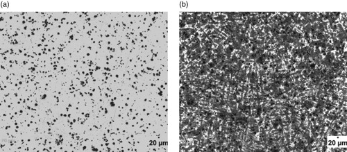
Table 4. Volume of Graphite, Pearlite and Ferrite in the Al alloyed ductile iron.
However, it can also be observed that the wt.% of Al contained in the ductile irons affected the nodular volume fraction. That is, the amount of non-spherical graphite increased with Al content greater than 3 wt.% in the ductile irons. The implication is that 3.02 and 3.74 wt.% Al in the ductile irons, hindered complete spheroidization process. It has been reported that aluminium presence disrupts uniformity in carbon diffusion at the surface layer of austenite towards the graphite leading to reduction in its sphericity [Citation25]. In addition, due to the increased nucleation sites for graphite precipitation and their distribution in the matrix, the growing graphite nodules may impinge on one another, resulting in non-sphericity of the graphite. Hence the explanation for some vermicular type graphite also observed in the ductile irons [Citation12].
The Al content also influenced the proportions of the graphite types contained in the ductile irons, although they consist majorly of types VI, V and IV graphite. The matrix of 3.74% Al-ductile alloy contains 80% of graphite type VI – IV of sizes 6 and 7 in various proportions. This is with more portion of type IV. However, 2.29% Al-ductile iron gives the optimum microstructural features with 85% of type VI –IV, The type VI being 25% of it but with traces of type III. Other Al alloyed ductile iron compositions contain the type III, a vermicular type of graphite nodules in various proportion, with the 1.05% Al alloyed ductile iron having the highest proportion of this graphite type in its matrix structures. The sizes of the nodules were observed to generally decrease with Al addition in the ductile irons, which are on account of the enhanced nucleation sites for graphite precipitation facilitated by Al. The 2.29 wt.% Al alloyed ductile iron produced the least sizes of 7 and 8 for the various graphite types it contained. This is in agreement with the work of Soinski et al. [*Citation26] and; Kiani-Rashid and Edmonds [*Citation11], where it was reported that in the presence of aluminium, graphitization process into smaller nodular sizes is greatly enhanced but absolute spheroidization is hindered.
Figures – show the microstructures of the ductile irons which were used for the phase quantification and characterization. It is observed that the matrix structures consists of pearlite (dark) and ferrite (light) phases with graphite nodules embedded in them. Precisely, it can be seen from Table that ductile iron compositions containing 3.02 and 3.74 wt.% Al had higher pearlite contents of 55.95 and 66.40%, respectively. Both compositions were also linked with low nodules volume fraction, which implies that though the nodules count are more, they are relatively smaller in size which is a direct effect of Al on the Fe-C-Al alloy system [Citation12].
3.2.2. SEM-EDS analyses
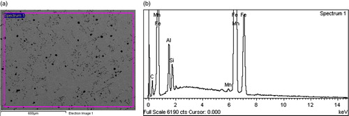
Figures show representative secondary electron mode images and EDS profiles of some of the Al alloyed ductile irons produced. The micrographs confirm the presence of nodular graphite morphology in the ductile irons, which have already been described in Figures –; while the EDS profiles confirm that Al is an alloying addition present in the ductile irons produced.
Figure 7. (a) SEM-EDS electron image of 1.05% Al-ductile cast iron. (b) EDS Graph of 1.05% Al-ductile cast iron.
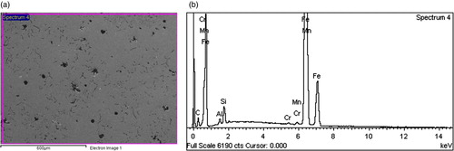
Figure 8. (a) SEM-EDS electron image of 2.29% Al-ductile cast iron. (b) EDS Graph of 2.29% Al-ductile cast iron.
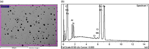
Figure 9. (a) SEM-EDS electron image of 3.02% Al-ductile cast iron. (b) EDS Graph of 3.02% Al-ductile cast iron.
3.2.3. XRD analyses
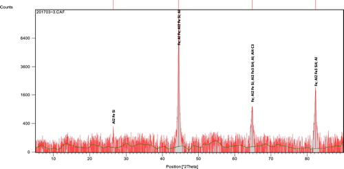
Representative X-ray diffractograms of the ductile irons are presented in Figures and . The profiles which were analysed using a high score X’Pert software, indicated the peak positions, identified pattern lists and sets of miller indices (011, 002, 112), (111, 022, 113, 222, 004) and (111, 002, 022, 113, 222). From the sets of diffracting crystal planes, body-centred cubic (BCC) ferrite and its mixture with face-centred cubic (FCC) were confirmed. This is suggestive that pearlite structure which is a mixture of ferrite and cementite is found as phases in the ductile irons. Apart from the two main phases of ferrite, cementite and/or their mixture as pearlite, some other compounds were also identified in the pattern. These include: Aluminum-Silicon-Carbide (Al4SiC4), Magnesium-Silicon (Mg2Si), Aluminum-Iron-Silicon (Al2Fe3Si4 and Al5FeSi), Aluminum-Carbide (Al4C3) and Aluminum-Iron (AlFe). The phases identified in the ductile irons produced are principally in agreement with that reported by [*Citation27–28].
Figure 10. Intensity (counts) against 2 theta (degree) of 1.575% Al-ductile cast iron alloy produced.
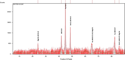
Figure 11. Intensity (counts) against 2 theta (degree) of 2.29% Al-ductile cast iron alloy produced.
3.3. Mechanical properties of the Al-ductile cast iron produced
The mechanical test results of the ductile irons produced are presented in Figures . It is observed from Figures and that the hardness and ultimate tensile strength of the ductile irons increased with increase in Al content. For the hardness values, (that is, in comparison with the as-cast ductile iron composition), increase of 3%, 11%, 29.6%, 13% and 46% were attained with the use of 1.05, 1.575, 2.29, 3.02, and 3.74 wt.% Al, respectively. It could be deduced that the hardness values were basically at the same level for the ductile irons containing 3.02 and 3.74 wt.% Al. For the ultimate tensile strength, there was increase of 6%, 16.4%, 17.9%, 20.3%, and 23.8% with the addition of 1.05, 1.58, 2.29, 3.02 and 3.74 wt.% Al, respectively. The significantly improved hardness observed in the ductile irons containing 3.03 and 3.74 wt.% Al, may be attributed to the increase in the pearlite content achieved for both compositions (55.95% and 66.40%, respectively as observed in Table ), which resulted in phase strengthening. The strengthening mechanism was on account of solid solution strengthening the effect of the aluminium and boundary strengthening on account of the refinement of grain sizes of the ductile irons. The solid solution strengthening impacted by the aluminium and fine graphite precipitates observed in the matrices also enhance the strength of the ductile irons. In addition, the presence of Al also resulted in the formation of some intermetallic compounds within the matrix structure which contributed to the increased strength observed in the Al alloyed ductile irons [Citation29,Citation1]. This claim is supported by microstructural evidences as presented in Figures – and Table , and also agrees with findings from related works [Citation30–31,Citation2,Citation7].
Figure 12. Variation of hardness values (HV0.1) with aluminium content (wt%) in ductile cast iron produced.
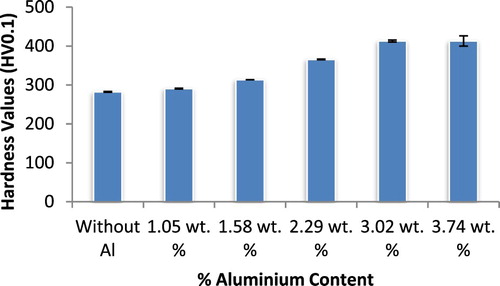
Figure 13. Variation of ultimate tensile strength withaluminium content (wt%) in ductile cast iron produced.
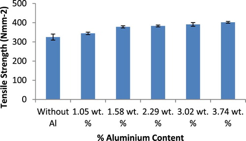
Figure 14. Variation of % elongation with aluminium content (wt%) in ductile cast iron produced.
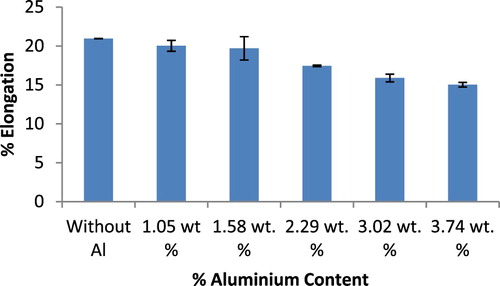
Figure 15. Variation of impact toughness with aluminium content (wt%) in ductile cast iron produced.
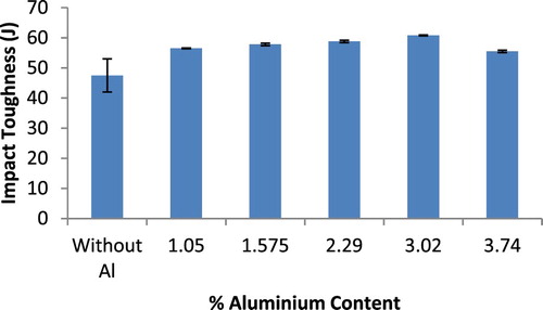
The percentage elongation results of the ductile irons are presented in Figure . It is observed that the elongation values unlike the hardness and tensile strength results, scales inversely with increase in Al content in the ductile irons. The values decreased from 20.96% for the as-cast ductile iron composition to 15% for the ductile iron composition containing 3.74 wt.% Al. It is well established for ferrous materials that strength increases is usually accompanied with decreased ductility. It is however noted that the ductility values recorded for the ductile irons, is within the range 12–22% specified in [*Citation32] standard. Also, the ductility reduction is not so as significant. It is posited that the improved graphitization and nodule counts in the Al alloyed ductile irons, coupled with reasonable ferrite phase proportion, contributed to the satisfactory ductility values observed despite the high strength of the ductile irons [Citation31]. In the case of impact strength (Figure ), it is observed that the values for the Al alloyed ductile irons produced increased with an increase in the % Al up to 3.02 wt.%, and decreased for the ductile iron composition containing 3.74 wt.% Al. This suggests that the composition containing 3.74 wt.% Al may not be so suitable for applications requiring a good combination of strength and toughness compared with the composition containing 2.29 and 3.02 wt.% Al. It can be argued that the generally enhanced nodules count facilitated by the aluminium addition, help serve as crack arrester, which increases the ductile iron resistance to crack propagation thereby leading to an improvement in the toughness [Citation33].
4. Conclusion
In this study, the microstructural characteristics and mechanical properties of rotary melting furnace processed Al alloyed ductile irons were investigated. From the results, the following conclusions are drawn:
The ductile irons consist essentially of nodular and vermicular type graphite distributed in a predominantly pearlite – ferrite matrix structure – features attesting to the viability of rotary melt processing for ductile iron production.
nodule count increases with an increase in Al wt.% but nodule sizes and degree of nodule sphericity decrease with an increase in Al wt.% in the ductile irons.
The hardness, tensile strength and to an extent, impact toughness of the ductile irons increased with an increase in Al wt.%, but the ductility decreased slightly with an increase in Al wt.%.
The ductile iron compositions containing 2.29 and 3.02 wt.% Al were considered to have the best combination of mechanical properties of the ductile irons produced.
Disclosure statement
No potential conflict of interest was reported by the authors.
ORCID
A. O. Adebayo http://orcid.org/0000-0001-5446-6760
References
- Cocco VD, Iacoviello D, Iacoviello F, et al. Graphitenodules Influence on DCIs mechanical properties: experimental and Numerical Investigation. Procedia Engineering. Procedia Eng. 2015;109:135–143. doi: 10.1016/j.proeng.2015.06.223
- Kiani-Rashid AR. Influence of austenitising conditions and aluminium content on microstructure and properties of ductile irons. J Alloys Compd. 2009;470:323–327. doi: 10.1016/j.jallcom.2008.02.070
- Kashani S, Boutorabi SMA. As-Cast acicular ductile aluminium Cast iron. J Iron Steel Res Int. 2009;16(6):23–28. doi: 10.1016/S1006-706X(10)60022-2
- Agostinoa LD, Coccoa VD, Fernandinob DO, et al. Damaging micromechanisms in an As Cast Ferritic and a Ferritized ductile Cast iron. Procedia Structural Integrity. 2017;3:201–207. doi: 10.1016/j.prostr.2017.04.045
- Omole SO, Oyetunji A, Alaneme KK, et al. Structural characterization and mechanical properties of pearlite – enhanced micro-alloyed ductile irons. J King Saud Univ – Eng Sci. 2018 ( Article in Press).
- Tong G, Zengqiang L, Junhao F, et al. Preparation of a Novel Mg–Fe Master alloy and its Spheroidizing effect on graphite in ductile irons. Results Phys. 2018;10:155–159. doi: 10.1016/j.rinp.2018.05.035
- Haqu MM, Young JM. Production of Spheroidal graphite aluminium Cast iron and the factors affecting it. J Mater Process Technol. 1995;55:186–192. doi: 10.1016/0924-0136(95)01952-9
- Haghdadi N, Bazaz B, Erfanian-Naziftoosi HR, et al. Microstructural and mechanical properties of Al-alloyed ductile iron upon casting and annealing. Int J Miner, Metall Mater. 2012;19(9):812–820. doi: 10.1007/s12613-012-0633-z
- Jimenez J, Frommeyer G. The ternary iron-aluminium carbides. J Alloys Compd. 2011;509:2729–2733. doi: 10.1016/j.jallcom.2010.12.017
- Soiński MS, Góraj J. The influence of Cerium mixture addition on the structure of Cast iron containing about of 5% aluminium. Arch Foundry Eng. 2009;9(4):215–218.
- Kiani-Rashi AR, Edmonds DV. Microstructural characteristics of Al-alloyed austempered ductile irons. J Alloys Compd. 2009;477:391–398. doi: 10.1016/j.jallcom.2008.10.038
- Soiński MS, Kordas P, Skurka K, et al. Investigations of Ferritic nodular Cast iron containing about 5-6% aluminium. Arch Foundry Eng. 2016;16(4):141–146. doi: 10.1515/afe-2016-0099
- Kopyciński D. Effect of Ti, Nb, Cr and B on structure and mechanical properties of high aluminium Cast iron. Arch Foundry Eng. 2013;13(1):77–80. doi: 10.2478/afe-2013-0015
- Fras E, Kopycinski B, Lopez-Hugo F. Processing and properties of high aluminium Fe-Al-C alloys. Int J Cast Met Res. 2012;15(1):9–16. doi: 10.1080/13640461.2002.11819458
- Ziółkowskia E, Wrona R. Using fuzzy optimisation method in calculation of charge burden to correct the chemical composition of metal melt. Arch Foundry Eng. 2007;7(3):183–186.
- Khanna OP. Materials Science and Metallurgy. Dhanpat Rail Publication Limited, New Delhi, 2009.
- Alasoluyi JO, Omotoyinbo JA, Olusunle SOO, et al. Investigation of the mechanical properties of ductile iron produced from Hybrid inoculants using rotary furnace,International. J Sci Technol. 2013;2(5):388–393.
- ISO 6892-1-2016. Metallic materials- tensile testing- Part 1: method of test at Room temperature.
- ISO 148-1-2016. Metallic materials- Charpy Pendulum impact test- Part 1: test method.
- ISO 6507-1-2018. Metallic materials-Vickers hardness test- Part 1: test method.
- Seidu SO, Riposan I. Thermal analysis of innoculated ductile irons. U.P.B. Science Bulletin, B:73. 2014: 13–23.
- PN ISO 945-1. Microstructure of cast iron – Part 1: graphite classification by visual analysis.
- ISO 16112. Compact (vermicular) graphite Cast irons – classification.
- Soiński MS, Jakubus A, Kordas P, et al. The effect of aluminium on graphitization of Cast iron treated with Cerium mixture. Arch Foundry Eng. 2014;14(2):95–100. doi: 10.2478/afe-2014-0044
- Shayesteh-Zeraati A, Naser-Zoshki H, Kiani-Rashid AR, et al. The effect of aluminium content on morphology, size, volume fraction and number of graphite nodules in ductile Cast iron. Proc. IMechE, Part L. 2010;224.
- Soiński MS, Jakubus A, Kordas P, et al. Characteristics of graphite Precipitate in aluminium Cast iron treated with Cerium mixture. Arch Foundry Eng. 2015;15(1):93–98. doi: 10.1515/afe-2015-0017
- Palm M. Concepts derived from phase diagram studies for the strengthening of Fe-Al based alloys. Intermetallic. 2005;13:1286–1295. doi: 10.1016/j.intermet.2004.10.015
- Connectable D, Lacaze J, Maugis P, et al. A Calphad assessment of Al-C-Fe system with the K-carbide modelled as an ordered form of the FCC phase. Comput Coupling Ph Diagr Thermochem. 2008;32:361–370. doi: 10.1016/j.calphad.2008.01.002
- Shayesteh-Zeraatia A, Naser-Zoshkib H, Kiani-Rashid AR. Microstructural and mechanical properties (hardness) investigations of Al-alloyed ductile cast iron. J Alloys Compd. 2010;500:129–133. doi: 10.1016/j.jallcom.2010.04.003
- Hampl J, Elbel T, Valek T. European Union Metal. Conference Brno; May 21-23, 2014; Czech Republic.
- Gonzaga RA. Influence of ferrite and pearlite content on mechanical properties ductile cast irons. Mater Sci Eng A. 2013;567:1–8. doi: 10.1016/j.msea.2012.12.089
- ISO 1083-2005. Spheroidal graphite cast irons – Classification.
- Shaba SK, Dyuti S, Haque MM, et al. Development of New Route for Fe-C-Al Cast iron production. J Appl Sci. 2010;10(12):1196–1199. doi: 10.3923/jas.2010.1196.1199