
 ?Mathematical formulae have been encoded as MathML and are displayed in this HTML version using MathJax in order to improve their display. Uncheck the box to turn MathJax off. This feature requires Javascript. Click on a formula to zoom.
ABSTRACT
In this article, a theoretical analysis is carried out to understand the role of electrokinetic effect on transient natural convection flow in a vertical microchannel. By incorporating the electrokinetic body force and the natural convection term in the classical Navier–Stokes equations, the governing momentum equation for the current investigation is developed and solved analytically using the classical Laplace transform technique. Due to the complexity of solutions obtained in Laplace domain, the Riemann-sum approximation (RSA) technique is used to transform the solutions from Laplace domain to time domain. For accuracy check, the steady-state solution is also computed and compared with the implicit finite difference method and RSA at large time. Results show that skin-friction at the walls as well as the mass-flux can be optimized by careful selection of flow controlling parameters. In addition, it is found that the time required to attain steady-state skin-friction and mass-flux is weakly dependent on EDL size while strongly dependent on Knudsen number.
Nomenclature
| = | specific heats at constant pressure and constant volume, respectively | |
| = | dimensional streaming potential | |
| = | dimensionless streaming potential (dimensionless) | |
| = | Faraday’s constant (dimensionless) | |
| = | acceleration due to gravity | |
| = | Grashof number (dimensionless) | |
| = | dimensionless parameter | |
| = | spacing between the microchannel walls | |
| = | dimensionless volume flow rate (dimensionless) | |
| = | universal gas constant | |
| = | dimensionless mass-flux (dimensionless) | |
| = | dimensional time | |
| = | dimensionless time (dimensionless) | |
| = | dimensional temperature | |
| = | ambient fluid temperature | |
| = | temperature of the wall at | |
| = | temperature of the wall at | |
| = | absolute temperature | |
| = | axial velocity | |
| = | dimensionless axial velocity (dimensionless) | |
| = | vectorial velocity profile | |
| = | valence number of ions in the solution (dimensionless) | |
| = | axial and transverse coordinates respectively | |
| = | dimensionless axial coordinate (dimensionless) | |
| = | dimensionless transverse coordinate (dimensionless) |
Greek letters
| = | thermal diffusivity | |
| = | thermal expansion coefficient | |
| = | dimensionless variables (dimensionless) | |
| = | fluid permittivity | |
| = | dimensional zeta-potential | |
| = | dimensionless zeta-potential (dimensionless) | |
| = | wall-ambient temperature difference ratio (dimensionless) | |
| = | thermal and tangential momentum accommodation coefficients, respectively (dimensionless) | |
| = | ratio of specific heats ( | |
| = | fluid–wall interaction parameter, | |
| = | magnitude of electrokinetic effect (dimensionless) | |
| = | electrostatic potential | |
| = | externally imposed electrostatic potential | |
| = | Debye–Hückel parameter (dimensionless) | |
| = | mean free path | |
| = | Debye length | |
| = | dimensional EDL potential | |
| = | dimensionless EDL potential (dimensionless) | |
| = | fluid thermal conductivity | |
| = | fluid dynamic viscosity | |
| = | fluid density | |
| = | skin-friction (dimensionless) | |
| = | kinematic viscosity | |
| = | charge density | |
| = | dimensionless temperature (dimensionless) |
1. Introduction
The study of time-dependent natural convection flow in a vertical channel is a known problem in the literature. In parallel plates channel, Jha et al. [Citation1] obtained an exact solution for the transient free convective flow of a viscous and incompressible fluid in a vertical channel due to symmetric heating of channel walls. The correlation between time to attain steady state and Prandtl number is established and they concluded that nature of relationship is linear when Prandtl number is greater than one and cubic for Prandtl number less than one. Later, Singh and Paul [Citation2] analytically studied transient natural convection between two vertical walls heated/cooled asymmetrically and concluded that there exists a formation of upward flow closed to the heated wall while the downward flow is formed near the cooled wall for negative value of buoyancy distribution parameter. Other related physical articles on transient natural convection flow are available in [Citation3–5]. Natural convection in a vertical microchannel on the other hand has significant application in micro-electro-mechanical-system (MEMS) and nano-electro-mechanical systems (NEMS) designs as cooling mechanism. Though there are notable number of scientific, engineering and industrial applications found for MEMS devices, further understanding of flow formation and heat transfer enhancement in such MEMS devices is still far from being detailed. On the other hand, the performance of MEMS frequently disobeys calculations made using scaling laws developed for large systems. So, heat can be easily built up in a densely packed MEMS protective housing, which results to undesirable or even destructive deformation [Citation6]. Therefore, there is a demanding necessity for reliable computational competences for accurate predictions of these devices.
It has been established that the Knudsen number is the key parameter which decides the division of rarefied gas flow [Citation6–8] and can be defined as the fraction of the molecular mean free path to characteristic length scale. For a given fluid flow problem, when
, the flow domain can be treated as a continuum flow, in which the Navier–Stokes equation in conjunction with the no-slip wall boundary conditions become applicable. In the case of Knudsen number greater than 10
, the flow becomes unrestricted molecule in nature, because of insignificant molecular collisions. For
, the slip flow regime is considered and the no-slip boundary condition becomes invalid, though continuum conservation equations are used to characterize the bulk flow. A number of articles have been dedicated to predict flow formation and heat transfer problems in microchannel. Chen and Weng [Citation9] analytically studied the steady fully developed natural convection in an open-ended vertical parallel plate microchannel with asymmetric wall temperature. It was established that rarefaction and fluid wall interaction effects enhance volumetric flow rate and reduce heat transfer. This result was later extended by taking into account suction/injection on the microchannel walls by Jha et al. [Citation10]. They resolved that suction/injection parameter intensely influences skin-friction as well as rate of heat transfer. Other related works on flow formation in vertical microchannel can be found in [Citation11–13].
The analysis of the electrokinetic effect on flow formation has been widely studied in relation to pressure gradient. The electrokinetic phenomenon gets its applications in laboratory experimentations, industrial and engineering applications such as the removal of contaminants in soil and imposing electric ion on flow formation [Citation14]. It involves the passing of low-voltage direct current electric field across the boundary of a fluid. Other applications can be found in medical field for cardiopulmonary resuscitation and development or recharging of battery cells [Citation14]. When a liquid containing small amount of ions is brought in contact with a solid boundary, the like charges repel while the unlike charges attract. This condition leads to the formation of electric-double layer (EDL) closed to the walls containing excess counter ions. The pioneer works available on electrokinetic effect are Reuss [Citation15] and Probstein [Citation16]. Since then, different experimental and analytical studies have been carried out for further understanding of this phenomenon. Helmholtz [Citation17] formulated the theory of EDL, which relates the electric field and flow parameters for electrokinetics, Patankar and Hu [Citation18] derived a numerical simulation of microfluidic injection using electroosmotic force through the intersection of two channels. Ren and Li [Citation19] examined the electroosmotic flows in microchannels with axially non-uniform zeta potentials for variable cross-sections. One of the major approximations used in the study of electroosmotic flow is the Debye–Hückel approximation [Citation20] which is applicable when the electric potential is low. Yang and Li [Citation21] employed the Debye–Hückel approximation to develop a numerical algorithm for electrokinetically driven Newtonian liquid flow. They found that for a liquid solution of low ionic concentration and a solid surface of high zeta-potential, the liquid flow in rectangular microchannel is clearly controlled by the presence of the EDL field and hence deviates from the flow characteristics described by classical fluid mechanics. Recently, many contributions have been communicated to study the combined effect of pressure and electrokinetic effects on flow formation in channel and microchannel [Citation22–27]. Mukhopadhyay et al. [Citation22] presented an exact solution to investigate the fully developed hydrodynamic and thermal transport of combined pressure and electrokinetically driven flow with asymmetric boundary condition. They established that both heat transfer characteristics and flow formation are significantly affected by the asymmetries in wall boundary conditions for both purely electroosmotic and combined pressure-driven and electroosmotic flows. Peralta et al. [Citation28], Medina et al. [Citation29], Soong and Wang [Citation23] and Jha and Oni [Citation30] gave a theoretical analysis on the effects of asymmetries in wall conditions and zeta-potential on electrokinetic flows in a microchannel and concluded that the asymmetric conditions have significant effect on flow formation, temperature distribution and heat transfer. Other related reviewed references can be found in [Citation31–34].
Generally, flows in the vertical microchannel are often been acted upon by force of gravity. Also, unequal wall heating at the microchannel walls leads to density difference thereby setting up natural convection current in the microchannel. This phenomenon has been widely neglected by researches in the study of electroosmotic flow. Recently, Khan et al. [Citation35] investigated the mixed convection in a vertical channel in the presence of electrical double layers and found that the flow formation is slightly dependent on Debye–Hückel parameter.
The aim of this study is to theoretically examine the electrokinetic effect on transient natural convection flow in a vertical microchannel subjected to asymmetric zeta-potential and asymmetric wall heating.
The novelty of this analysis is to discuss the role of electrokinetic effect on transient natural convection flow formation in a vertical microchannel subjected to asymmetric wall heating. In application, it is hoped that this study will help in understanding flow formation enhancement and minimization of skin-friction at the microchannel walls. The transient as well as steady-state solutions (SSS) are obtained using the combination of Laplace transform techniques as well as Riemann-sum approximation (RSA) approach and method of underdetermined coefficients. Also, the implicit finite difference (IFD) approach is used to justify the accuracy of the solution obtained. Furthermore, the impact of various controlling parameters on flow formation is discussed with the help of graphs and tables.
2. Mathematical analysis
In this article, we considered a transient, laminar, fully developed flow in a vertical microchannel of width with non-uniform wall temperatures of
and
and electric potentials
and
at the walls
and
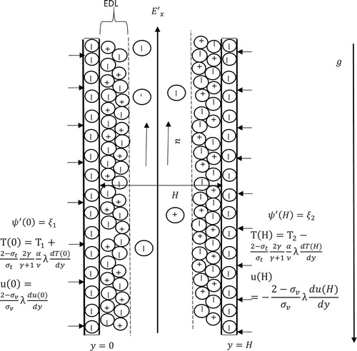
, respectively. The temperature difference at the walls results to density difference, which induced natural convection current the microchannel. In this current article, flow formation is assumed to be driven by combined externally applied voltage gradient and buoyancy force as displayed in Figure . The charge distribution in the EDL follows Boltzmann distribution, therefore, the effects ion convection are negligible. Also, the wall potentials are considered low enough for Debye–Hückel linearization to be valid. This has been proven to be a valid assumption for flow formation in micro-geometries [Citation36]. Furthermore, the externally applied voltage is significantly higher than the flow-induced voltage. Except otherwise stated, all other thermodynamics and hydrodynamics physical parameters are assumed constant.
Figure 1. Schematic of the problem.
Based on the above assumptions, the electrical potential distribution is gotten from Poison–Boltzmann equation as
(1)
(1) The potential,
is as a result of externally imposed field
and EDL potential
, where,
is the vector differential operator and
is the net volume charge density of symmetric electrolyte and defined as [Citation37]
(2)
(2)
Since this current investigation is concern with the fully developed region, the external potential gradient is along axial direction only, i.e. and
. So that
(3)
(3) subject to the boundary conditions:
(4)
(4) The momentum equation for the current investigation is obtained by incorporating the electrokinetic body force to the Navier–Stokes equation in the axial direction only.
Using Boussinesq approximation defined by
(5)
(5)
Incorporating the Boussinesq approximation, the governing momentum and energy equations describing the flow formation and temperature distribution in the dimensional form are respectively given by
(6)
(6)
(7)
(7) subject to the following conditions:
(8)
(8) where
is the electric body force which represents the impact of EDL on transient flow formation in the vertical microchannel,
is the molecular mean free path and
is the tangential momentum accommodation coefficient,
is the thermal accommodation coefficient which depends on the fluid and surface materials, particularly for air and water, it assumes typical values near unity [Citation7]. The boundary conditions (8) represent the velocity slip and the temperature jump at the walls
and
.
2.1. Dimensionless analysis
The following dimensionless parameters are employed to transform the governing equations (1)–(8) into their respective dimensionless forms:
(9)
(9)
Using the dimensionless parameters defined in (9), and considering the fact that the wall potential is assumed low enough for Debye–Hückel linearization to be valid, Equations (3)–(8) describing the electric potential, flow formation and temperature distribution in the vertical microchannel are respectively given in dimensionless form as
(10)
(10)
(11)
(11)
(12)
(12)
(13)
(13)
with the initial and boundary conditions:
(14)
(14)
2.2. Analytical solution
Solving Equation (10) with boundary conditions (11), the electric potential is obtained as
(15)
(15) The temperature distribution as well as velocity profile in the vertical microchannel is also obtained by solving the energy and momentum equations, respectively. Since these equations are time-dependent, it is convenient to use the well-known Laplace transform technique to transform the partial differential equations into ordinary differential equations as follows:
where
is the Laplace transform parameter which is greater than zero for convergence.
Taking the Laplace transform of Equations (12) and (13), with boundary conditions (14) and solving the transformed ordinary differential equations, the temperature distribution as well as velocity distribution are respectively obtained in Laplace domain as follows:
(16)
(16)
(17)
(17)
The skin-frictions at the microchannel walls and
are respectively deduced in the Laplace domain as
(18)
(18)
(19)
(19)
Also, the dimensionless mass-flux in the Laplace domain is given by
(20)
(20)
2.3. Riemann-sum approximation
The solutions obtained in Equations (16)–(20) are in the Laplace domain and need to be transformed to time domain in order to ascertain the aim of this current analysis. Due to the complexity of the closed-form expressions obtained in Laplace domain, a numerical Laplace inversion technique used in [Citation38–41], which is based on the RSA, is employed. This numerical Laplace inversion technique has been seen to be a useful and reliable tool in obtaining time-dependent problems [Citation4,Citation39]. In this technique, the temperature distribution, velocity profile, skin-friction and mass-flux which are in Laplace domain are inverted to the time domain respectively as follows:
(21)
(21)
(22)
(22)
(23)
(23)
(24)
(24)
(25)
(25) where
denotes to the real part,
the imaginary number.
is the number of terms used in the RSA and
is the real part of the Bromwich contour that is used in inverting Laplace transforms. The Riemann-sum Laplace inversion approximation involves a single summation for the numerical process. Its correctness depends on the value of
and the truncation error dictated by
. According to Tzou [Citation41] and based on inspection, the value of
that best satisfied the result is 4.7.
2.4. Steady-state solution
It is worth computing the steady-state value for temperature distribution and velocity profile in the vertical channel as it helps to validate the accuracy of the RSA approach used in Equations . It is expected that at large time, the RSA results should correspond with the SSS. The SSS are obtained by taking
in Equations (12) and (13), and solving the ordinary differential equation under relevant boundary conditions. The following exact solutions are obtained for temperature distributions and velocity profile respectively at steady state:
(25)
(25)
(26)
(26) where
are constants defined in the Appendix.
In many research works, the externally applied electric field is often prescribed. This assumption deviates from the physics of electroosmotic flow, therefore, the electric field strength shall be computed in this current research. It is known that the electrical field generated is driven by a hydrostatic pressure through a microchannel with charged walls, which results in a streaming current, defined in dimensionless form as [Citation35]
(27)
(27)
Also, the streaming potential produces a conduction current in the reverse direction, which is given in dimensionless form as
(28)
(28)
At steady state, the sum of the streaming current and the electrical conduction current equals zero, so that
(29)
(29) So that
(30)
(30) where
is a constant.
By the use of Equation (30), the dimensionless streaming potential is obtained as
(31)
(31) where
are constants defined in the Appendix.
By the use of the exact solution obtained for velocity profile in Equation (26), the skin-frictions at the channel walls are obtained as
(32)
(32)
(33)
(33)
The mass-flux in the vertical microchannel at steady state is given as
(34)
(34)
2.5. Implicit finite difference approach
By employing the IFD method, the electric potential, energy and momentum equations given in (10)–(14) are solved. This involves discretization of the equations into finite difference equations at the grid point . The discretized electric potential, momentum and energy equations respectively become [Citation42]
(35)
(35)
(36)
(36)
(37)
(37)
Subject to:
(38)
(38)
(39)
(39)
The indexes “i” and “j” represent and
respectively. The backward difference formula is used for the time derivative, while the central difference formula is used for other spatial derivatives. The equations given above are solved using the Thomas algorithm which involves the complex manipulation of a system of linear algebraic equations in the tridiagonal form.
In each time step, the solution to the electric potential was first obtained. This followed by the temperature distribution
after which the velocity,
is obtained by using the already known values of
and
. The computation process is continued further, until a steady state is approached which satisfies the following convergence criterion [Citation43]:
(40)
(40) We have that
stands for the velocity, temperature fields and electric potential,
is the number of interior grid points and
is the maximum absolute value of
.
In our numerical computation, we have chosen 51 grid points for the numerical variable. Also, it is very necessary to be careful in specifying the value of, in order to obtain a steady-state result as quickly as possible, but also not too small enough to avoid instabilities. Hence, for this computation, it is set to
(41)
(41) The parameter “stabr” is determined by numerical experiment in order to achieve convergence and stability of the solution procedure. After concise tests, it was observed that the value 1.0 was suitable for the numerical computations.
While trying to ascertain the accuracy of the numerical procedure, the results of this present approach (IFD) are compared with that of the analytical solution obtained for the steady state as well as those of RSA at large time. This comparison justifies the reliability of solution techniques (Table ).
Table 1. Numerical comparison of velocity profile for different solution method at  .
.
3. Results and discussion
In this article, the role of the electrokinetic effect on transient natural convection flow in a vertical microchannel is presented semi-analytically as well as numerically. For saltwater working fluid, the Prandtl number which controls the nature of fluid based and defined as the ratio of kinematic viscosity to thermal diffusivity. For further understanding on solutions obtained for flow formation and shear stress, line graphs are plotted to see the effects of various pertinent parameters governing flow formation. Throughout this article except as/where otherwise stated, the buoyancy force distribution parameter is taken from
which measures the level of asymmetric wall heating (
,
denote purely asymmetric heating and symmetric heating of the microchannel walls, respectively),
which denotes the microchannel walls zeta-potential, Debye–Hückel parameter
, which is inversely proportional to EDL size is taken over the range of
, the Grashof number controlling the buoyancy force strength is taken over
, the Knudsen number controlling the flow regime is taken over the range
to cover both the continuum and slip flow regimes. Except otherwise stated, the reference values in the present work are
,
. These values have been carefully selected to solve a physical problem in microfluidic [Citation22].
For accuracy check of the solution obtained, Table computes the velocity profile at different points in the microchannel for different values of using the RSA, exact solution (SSS) and the IFD approaches. This comparison gives an accurate agreement.
3.1. Streaming potential
Figure presents streaming potential as a function of Debye–Hückel parameter , Knudsen number and buoyancy force distribution parameter
for a fixed value of
,
at steady state. It is obvious from this figure that the maximum streaming potential is achieved at the slip regime
compare to the continuum regime
. In addition, increase in buoyancy force distribution parameter
leads to a corresponding increase in steaming potential. As expected, a careful look at this figure suggests that the streaming potential tends to zero as
. This is due to the fact that increasing
corresponds to a thinner EDL until no EDL is present.
Figure 2. Dimensionless streaming potential for different values of Kn and .
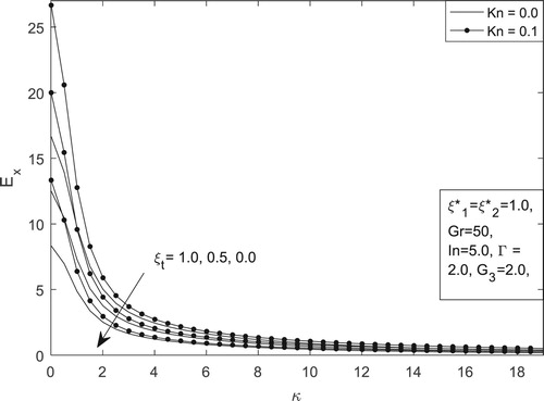
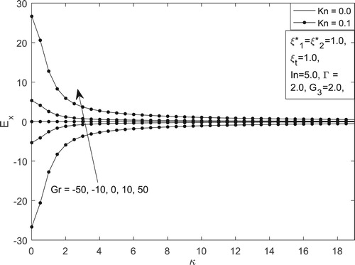
Figure on the other hand depicts the combined role of Knudsen number and
on streaming potential in the vertical microchannel. It is interesting to note an asymmetric behaviour in
between positive and negative values of
for different values of
and
. Also, it is found that streaming potential in the vertical microchannel can be enhanced by increasing the positive Grashof number.
Figure 3. Dimensionless streaming potential for different values of Kn and Gr.
3.2. Velocity profile
The main objective of this present study is to comprehend the role of the electrokinetic effect on transient natural convection flow in a vertical microchannel. In view of this, Figures – are attributed to this effect. Figure shows the influence of time and Knudsen number
on transient natural convection flow in a vertical microchannel at fixed value of other governing parameters. It is obvious from this figure that flow at continuum regime attains steady-state faster than flows in slip flow regime. This is due to the fact that at slip flow regime, the ratio of molecular mean free path to the channel width is higher and thereby enhancing fluid motion in the vertical microchannel compared to the continuum flow regime.
Figure 4. Velocity profile for different values of Kn and t.
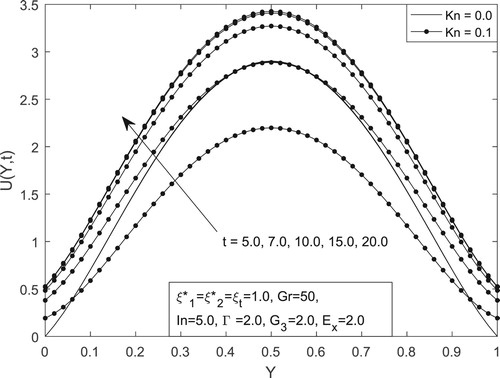
Figure 5. Velocity profile for different values of Gr and .
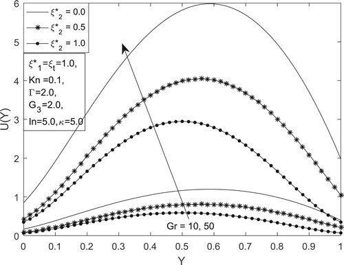
Figure 6. Velocity profile for different values of and
.
For proper understanding on the role of asymmetric wall zeta-potential, Figure illustrates the velocity profile for different values of Grashof number and
at steady state. It is interesting to note that flow formation in steady-state situation can be enhanced for purely asymmetric zeta-potential compared to symmetric or partially symmetric cases. In addition, increase in magnitude of buoyancy force leads to corresponding increase in flow formation in the microchannel. This could be attributed to the fact that increase in
increases the buoyancy force in the fluid which leads to rise in fluid motion.
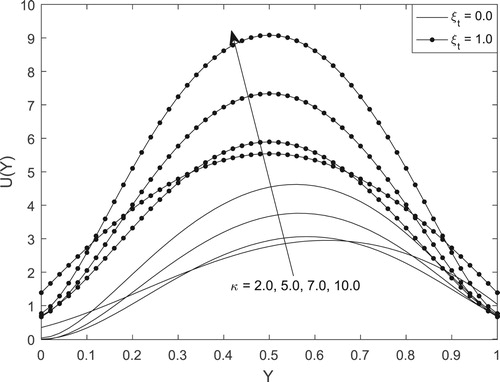
Figure on the other hand exhibits the steady-state velocity as a function of Debye–Hückel parameter and
at fixed value of
. It is obvious that fluid velocity in the vertical microchannel is higher for the case of symmetric heating case
compared to asymmetric wall heating case
regardless of the EDL size. Also, the maximum fluid velocity is observed in the central region of the microchannel for thin EDL
. From this figure, one can conclude that the presence of large EDL leads to retardation of fluid motion in the microchannel irrespective of symmetric or asymmetric wall heating conditions.
3.3. Skin-friction and mass-flux
Understanding the skin-friction as well as mass-flux of transient electrokinetic natural convection flow at microchannel walls has significant application in engineering designs such as drug delivery at microscale and batteries designs. Figures – represent the skin-friction as well as mass-flux, both at transient state as well as the steady-state situation. Figures and show the steady-state skin-friction for different values of and
at the walls
and
, respectively. It is evident that the role of EDL is to reduce the drag at the walls regardless of flow regime. On the other hand, skin-friction is maximum at both walls for purely asymmetric wall heating. Also, at the wall
, there exist point of inflexion while varying
. At this point, skin-friction is independent of
.
Figure 7. Skin-friction for different values of Kn and .
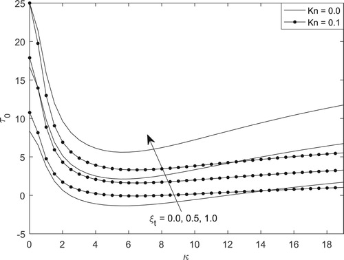
Figure 8. Skin-friction for different values of Kn and .
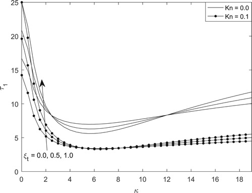
Figure 9. Mass flux for different values of Kn and .
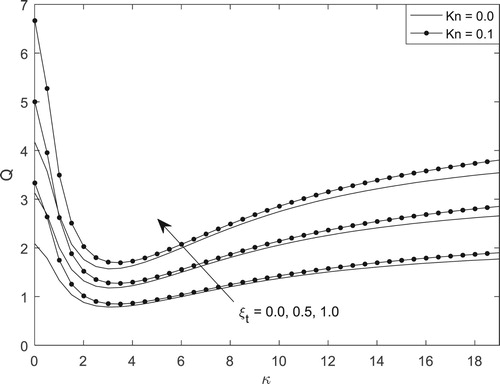
Figure 10. Mass flux for different values of Gr and .
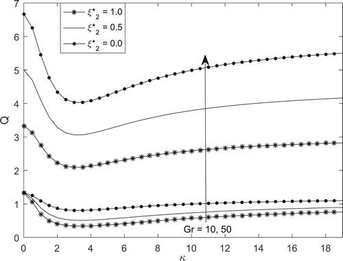
Figure 11. Skin-friction for different values of and
.
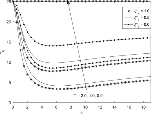
Figure 12. Skin-friction for different values of and
.
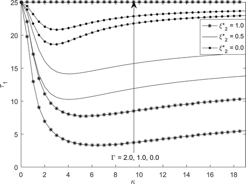
Figure 13. Skin-friction for different values of Kn and t (Y = 0).
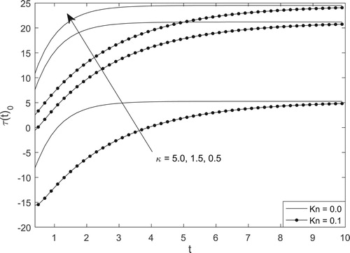
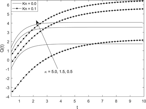
Figure 14. Mass-flux for different values of Kn and .
Figures and simulate the steady-state mass-flux by varying Debye–Hückel parameter , Knudsen number
and asymmetric wall zeta-potential
. Figure shows that mass-flux is higher in slip flow regime relative to the continuum flow regime regardless to the value of
. One can resolve that mass-flux can be enhanced by subjecting the walls to symmetric walls heating in slip flow regime. Figure on the other hand explains the importance of
and
on mass-flux in the microchannel. Also, it is observed that the amount of fluid passing through the microchannel can be enhanced by subjecting the walls to purely asymmetric zeta-potential and increasing the magnitude of buoyancy force. This is because an increase in buoyancy force leads to a corresponding increase in fluid velocity, thereby increasing the amount of fluid passing through the microchannel.
Figures and depict the variation of skin-friction at the walls and
respectively as a function of
and
. It is found from both figures that skin-friction at the microchannel walls can be minimized by increasing the magnitude of the electrokinetic effect, reducing the EDL length and subjecting the walls to symmetric wall zeta-potential.
Figures – present the steady-state skin-friction and mass-flux. It is paramount to understand the transient state skin-friction as well as mass-flux. A careful look at Figures and clearly reveal that for transient skin-friction and mass-flux, the time required to attain steady-state is weakly dependent on EDL size , while strongly dependent on Knudsen number. From Figure , the skin-friction at the wall
is seen to increase with time until steady state. This behaviour is also noticed for transient mass-flux.
The solutions obtained in this current article deserve pronounced attention not just because of their engineering applications in flow formation enhancement but can also serve as an accuracy check for various conducted experimental results.
4. Conclusion
A theoretical analysis is carried out to examine the role of electrokinetic effect on transient natural convection flow in a vertical microchannel subjected to asymmetric wall zeta-potential. Using the classical Navier–Stokes equation, the governing momentum partial differential equation is presented and solved using the Laplace transform technique and RSA. For numerical justification of result, the IFD approach is employed as well as the SSS is obtained and compared with the RSA solution. Based on the solutions as well as pictorial representations, the following conclusions are drawn:
Velocity, mass-flux and skin-friction increase with time until steady state is achieved.
Velocity profile and mass-flux in the microchannel can be enhanced by subjecting the walls to purely asymmetric zeta-potential.
Skin-friction at the microchannel walls can be minimized by considering symmetric zeta-potential and reducing Grashof number.
The streaming potential can be enhanced by considering large EDL subjected to symmetric wall heating.
Disclosure statement
No potential conflict of interest was reported by the authors.
References
- Jha BK, Singh AK, Takhar HS. Transient free convective flow in a vertical channel due to symmetric heating. Int J Appl Mech Eng. 2003;8(3):497–502.
- Singh AK, Paul T. Transient natural convection between two vertical walls heated/cooled asymmetrically. Int J Appl Mech Eng. 2006;11:143–154.
- Jha BK, Oni MO. Natural convection flow in a vertical tube inspired by time-periodic heating. Alexandria Eng J. 2016;55(4):3145–3151. doi: 10.1016/j.aej.2016.08.025
- Jha BK, Oni MO. Transient natural convection flow between vertical concentric cylinders heated/cooled asymmetrically. Proc IMechE Part A: J Power Energy. 2018;232(7):926–939. doi: 10.1177/0957650918758743
- Kao TT. Laminar free convective heat transfer response along a vertical flat plate with step jump in surface temperature. Lett Heat Mass Transf. 1975;2:419–428. doi: 10.1016/0094-4548(75)90008-9
- Jha BK, Oni MO. Electromagnetic natural convection flow in a vertical microchannel with Joule heating: an exact solution. J Taibah Univ Sci. 2018. doi:10.1080/16583655.2018.1494423.
- Jha BK, Oni MO, Aina B. Steady fully developed mixed convection flow in a vertical micro-concentric-annulus with heat generating/absorbing fluid: an exact solution. Ain Shams Eng J. 2016. doi:10.1016/j.asej.2016.08.005.
- Schaaf SA, Chambre PL. Flow of rarefied gases. Princeton (NJ): Princeton University Press; 1961.
- Chen CK, Weng HC. Natural convection flow in a vertical microchannel. J Heat Transf. 2005;127:1053–1059. doi: 10.1115/1.1999651
- Jha BK, Aina B, Joseph SB. Natural convection flow in a vertical micro-channel with suction/injection. J Process Mech Eng. 2014;228(3):171–180. doi: 10.1177/0954408913492719
- Yu S, Ameel TA. Slip-flow heat transfer in rectangular microchannels. Int J Heat Mass Transfer. 2001;44:4225–4234. doi: 10.1016/S0017-9310(01)00075-8
- Jha BK, Oni MO. Impact of mode of application of magnetic field on rate of heat transfer of rarefied gas flow in a microtube. Alexandria Eng J. 2017. doi:10.1016/j.aej.2017.03.029.
- Biswal L, Som SK, Chakraborty S. Effects of entrance region transport processes on free convection slip flow in vertical microchannels with isothermally heated walls. Int J Heat Mass Transfer. 2007;50:1248–1254. doi: 10.1016/j.ijheatmasstransfer.2006.09.025
- Arulanandam S, Li D. Liquid transport in rectangular microchannels by electroosmotic pumping. Colloids Surf A: Physicochem Eng Asp. 2000;161:89–102. doi: 10.1016/S0927-7757(99)00328-3
- Reuss FF. Sur un nouvel effet de l'électricité galvanique. Mém Soc Impériale Naturalistes Moscou. 1809;2:327–337.
- Probstein RF. Physicochemical hydrodynamics: an introduction. New York (NY): Wiley; 1994.
- Helmholtz H. Studien über electrische Grenzschichten. Ann Phys. 1879;243:337–382. doi: 10.1002/andp.18792430702
- Patankar NA, Hu HH. Numerical simulation of electroosmotic flow. Anal Chem. 1998;70:1870–1881. doi: 10.1021/ac970846u
- Ren L, Li D. Electroosmotic flow in heterogeneous microchannels. J Colloid Interface Sci. 2001;243:255–261. doi: 10.1006/jcis.2001.7824
- Debye P, Hückel H. The theory of electrolytes. I. Lowering of freezing point and related phenomena. Phys Z. 1923;24:185–206.
- Yang C, Li D. Analysis of electrokinetic effects on the liquid flow in rectangular microchannels, J Colloids Surf. 1998;143:339–353. doi: 10.1016/S0927-7757(98)00259-3
- Mukhopadhyay A, Banerjee S, Gupta C. Fully developed hydrodynamic and thermal transport in combined pressure and electrokinetically driven flow in a microchannel with asymmetric boundary conditions. Int J Heat Mass Transf. 2009;52:2145–2154. doi: 10.1016/j.ijheatmasstransfer.2008.08.035
- Soong CY, Wang SH. Theoretical analysis of electrokinetic flow and heat transfer in a microchannel under asymmetric boundary conditions. J Colloid Interface Sci. 2003;256:202–213. doi: 10.1016/S0021-9797(03)00513-7
- Matin MH, Khan WA. Electrokinetic effects on pressure driven flow of viscoelastic fluids in nanofluidic channels with Navier slip condition. J Mol Liq. 2016;215:472–480. doi: 10.1016/j.molliq.2016.01.034
- Laser D, Santiago J. A review of micropumps. J Micromech Microeng. 2004;14:R35–R64. doi: 10.1088/0960-1317/14/6/R01
- Chakraborty J, Ray S, Chakraborty S. Role of streaming potential on pulsating mass flow rate control in combined electroosmotic and pressure-driven microfluidic devices. Electrophoresis. 2012;33:419–425. doi: 10.1002/elps.201100414
- Jha BK, Oni MO. Fully developed mixed convection flow in a vertical channel with electrokinetic effects: exact solution. Multidiscipline Modell Mater Struct. 2018. doi:10.1108/MMMS-10-2017-0123.
- Peralta M, Arcos J, Mendez F, et al. Oscillatory electroosmotic flow in a parallel-plate microchannel under asymmetric zeta potentials. Fluid Dyn Res. 2017, in press. doi:10.1088/1873-7005/aa6dd1.
- Medina I, Toledo M, Méndez F, et al. Pulsatile electroosmotic flow in a microchannel with asymmetric wall zeta potentials and its effect on mass transport enhancement and mixing. Chem Eng Sci. 2018. doi:10.1016/j.ces.2018.03.051.
- Jha BK, Oni MO. Mathematical modelling of combined pressure driven and electrokinetic effect in a channel with induced magnetic field: an exact solution. J King Saud Univ – Sci. 2018. doi:10.1016/j.jksus.2018.10.0091018-3647.
- Umavathi JC, Kumar JP, Sheremet MA. Heat and mass transfer in a vertical double passage channel filled with electrically conducting fluid. Physica A. 2016. doi:10.1016/j.physa.2016.07.073.
- Umavathi JC, Sheremet MA. Mixed convection flow of an electrically conducting fluid in a vertical channel using Robin boundary conditions with heat source/sink. Eur J Mech B/Fluids. 2015. doi:10.1016/j.euromechflu.2015.08.013.
- Wang X, Qi H, Xu H. Transient electroosmotic flow of generalized second grade fluids under slip boundary conditions. Can J Phys. 2017;99:1–10.
- Yang X, Qi H, Jiang H. Numerical analysis for electroosmotic flow of fractional Maxwell fluids. Appl Math Lett. 2017. doi:10.1016/j.aml.2017.10.012.
- Khan NMD, Xu H, Zhao Q, et al. Analysis of mixed convection in a vertical channel in the presence of electrical double layers. Z Naturforsch. 2018. doi:10.1515/zna-2018-0097.
- Liechty BC, Webb BW, Maynes RD. Convective heat transfer characteristics of electro-osmotically generated flow in microtubes at high wall potential. Int J Heat Mass Transf. 2005;48:2360–2371. doi: 10.1016/j.ijheatmasstransfer.2005.01.019
- Yang RJ, Fu LM, Lin YC. Electroosmotic flow in microchannels. J Colloids Interface Sci. 2001;239:98–105. doi: 10.1006/jcis.2001.7551
- Jha BK, Apere CA. Unsteady MHD Couette flow in annuli: the Riemann-sum approximation approach. J Phys Soc Jpn. 2010;79(12):124403–124405. doi: 10.1143/JPSJ.79.124403
- Jha BK, Oni MO. An analytical solution for temperature field around a cylindrical surface subjected to a time dependent heat flux: an alternative approach. Alexandria Eng J. 2018;57(2);927–929. doi: 10.1016/j.aej.2017.01.003
- Khadrawi AF, Al-Nimr MA. Unsteady natural convection fluid flow in a vertical microchannel under the effect of the dual-phase-lag heat conduction model. Int J Thermophys. 2007;28:1387–1400. doi: 10.1007/s10765-007-0207-x
- Tzou DY. Macro to microscale heat transfer: the lagging behaviour. Washington: Taylor and Francis; 1997.
- Wang X, Qi H, Yu B, et al. Analytical and numerical study of electroosmotic slip flows of fractional second grade fluids. Commun Nonlinear Sci Numer Simul. 2017. doi:10.1016/j.cnsns.2017.02.019.
- Oztop HF, Abu-Nada E. Numerical study of natural convection in partially heated rectangular enclosures filled with nanofluids. Int J Heat Fluid Flow. 2008;29(5):1326–1336. doi: 10.1016/j.ijheatfluidflow.2008.04.009