
 ?Mathematical formulae have been encoded as MathML and are displayed in this HTML version using MathJax in order to improve their display. Uncheck the box to turn MathJax off. This feature requires Javascript. Click on a formula to zoom.
Abstract
A theoretical model is developed to investigate the density gradient driven instability in an plasma system with the consideration of finite temperature of both the electrons and the ions where these species are magnetized. The dependence of temperature of the electrons and ions, charge of the ions, plasma background density, and strength of magnetic field on the variation of normalized growth rate has been investigated and portrayed for different channel lengths. The ion temperature gradient that generally exists in the considered plasma systems is also included to investigate its impact on the growth rate of the instability.
1. Introduction
From the last more than two decades, Hall thrusters have been widely adopted among several propulsion devices because of their higher thrust to power ratio and lower input power. Hall thrusters find diverse applications in commercial space missions and also in telecommunication satellites [Citation1]. On account of electrons’ azimuthal drift, they are termed as closed drift thrusters. Depending on the framework and material of the discharged channel, thrusters are of usually two types: Anode Layer Thruster and Magnetic Layer Thruster. The latter is comprised of one expanded acceleration channel, whereas the former is composed of two-stage channels for acceleration and ionization separately, which are separated by an electrode [Citation2, Citation3]. Because of the existence of radial magnetic field and axial electric field, Hall thrusters provide large thrust density and a high impulse. This in turn results in the acceleration of propellants to an immense velocity. Both acceleration and ionization of the propellant are achieved inside the insulated discharge region (cylindrical chamber), called a channel, in the existence of radial magnetic field and axial electric field. The erosion of the channel walls may occur due to the bombardment of the ions and the electrons. Consequently, the lifetime and efficiency of Hall thrusters may be affected significantly [Citation3, Citation4]. Moreover, a disruption in the communication through satellites may occur because of the electrostatic charging, produced due to the existence of extensive exhaust beam divergence [Citation5]. Therefore, several imperative parameters like optimum thrust to power ratio, minimum erosion rate, lower beam divergence, etc. are required to be analyzed for establishing a hassle-free and an effective thruster’s operation. Distinct varieties of the instabilities are originated from the oscillations developed in the chamber.
Several varieties of discharge instabilities originated in Hall thrusters, within the domain of 103–109 Hz, have been discussed by Choueiri [Citation2]. The growth of Rayleigh instability in a Hall thruster channel in the presence of dust has been investigated by Malik et al. [Citation6]. The transport and characteristics effects of the electron drift instability in Hall-effect thrusters were explored by Lafleur et al. [Citation7]. High-frequency instability and phenomena of electron transport in a Hall thruster have been investigated by Lazurenko et al. [Citation8]. With the negligence of thermal motion of the plasma species, Litvak and Fisch [Citation9] have analytically investigated the gradient-driven Rayleigh-type instabilities in Hall thrusters. The numerical study of low-frequency oscillations in Stationary Plasma Thruster (SPT) have been carried out by Chable and Rogier [Citation10].
In the azimuthal direction, an electric field is generated because of the difference in electron and ion drift velocities in the Hall thrusters. In the same direction, it leads to the generation of the electrostatic waves. In the plasma, such waves could absorb free energy from the density gradient, built-up and lead to instability. Therefore, with the extensive interpretation of physical phenomena accountable for such instabilities, we can have a better analysis of efficiency of Hall thrusters. Hence, with the development of these devices, the concern of investigation of instabilities has always been the centre of attention for several researchers [Citation11–14]. Barral and Ahedo [Citation15] have been developed a low-frequency approach of breathing oscillations. Barral and Peradzynski [Citation16] have investigated the low-frequency oscillations under the impact of ionization. In the strong magnetic field regimes, Meezan et al. [Citation17] have investigated the impact of fluctuations to electron transport. In a coaxial discharge plasma, an approach to determine the azimuthal drift current has been devised by Thomas et al. [Citation18]. By dealing with the finite temperature of electrons, a theoretical model has been presented by Kapulkin and Guelman [Citation19] to analyse the low-frequency instabilities around anode regime. On the other hand, Sedighi et al. [Citation20, Citation21] have investigated relevant instabilities in fluid-conveying C-BN hybrid – or hetero-nanotube under a magneto-thermal environment. Makinde et al. [Citation22] have investigated the role of transverse magnetic field on the development of steady flow regime for an incompressible fluid in the boundary layer limit of a semi-infinite vertical plate. Khurana et al. [Citation23] have used linear theory based on normal mode to study the magneto-convection influenced by a gyrotactic behaviour of algal suspensions along with rotation in the nanoliquid layer.
In this paper, we have developed a theoretical model for analyzing density gradient driven instabilities in an plasma where a gradient exists in the ion and electron temperature. This is inspired due to the fact that under the action of cross field, the plasma species can have different drifts and collisions because of which there are fair chances of energy exchange and alteration of their distribution. This can lead to the gradient in temperature of the ions and electrons. In the proposed system two types of gradient-driven instabilities are found to evolve, out of which one grows with a very small rate and hence, is not evaluated in detail. The growth rate is investigated through the solution of the dispersion equation. The magnitude of normalized growth rate is determined and depicted as a function of the magnetic field, charge on ions, ion temperature gradient, channel length, background plasma density and temperature of the ions and electrons. The finding of this work shall play an imperative role in the technologies like electric propulsion [Citation24] and magnetized plasma sources used in plasma material interaction / surface processing [Citation25–28].
2. Mathematical formulation
In the present work, we have considered both the ions and the electrons to be magnetized under the impact of the external magnetic field (), applied in the z-direction. We have assumed non-zero temperatures of both the ions and the electrons; thus, a non-zero pressure-gradient term has been considered in the respective fluid equations. The two-dimensional adiabatic approximation is adopted to investigate the given system, i.e. space coordinates are chosen to be varied in the x – and y – directions.
In the present model, is the mass,
is the temperature and
is the density of the ions (
) and the electrons (
).
and
, respectively, are the charges of the electrons and the ions. V and U depict the velocities of the ions and the electrons, respectively. The oscillating and un-perturbed parts of densities are represented by
and
respectively, whereas those of velocities are represented by
and
, respectively. The electric field has its oscillating value as
and the associated potential is
. The oscillating quantities are taken to vary as ei(ωt − ky), where ω is the frequency of oscillations and
is the wavenumber associated with the oscillations of wavelength
.
Continuity equations and equations of motion for both the ion and electron fluids, in the linearized form, are written as
2.1. For ions
Continuity equation
(1)
(1)
The x-component of the equation of motion
(2)
(2)
The y-component of the equation of motion
(3)
(3)
2.2. For electrons
Continuity equation
(4)
(4)
The x-component of equation of motion
(5)
(5)
The y-component of the equation of motion
(6)
(6)
Here, and
, respectively, are the electron-cyclotron and ion-cyclotron frequencies. This can be noted that the ion and electron temperature gradients are also retained in the respective equation of motions, since the plasma species in the considered plasma systems carry finite temperatures and the temperature also shows a spatial variation. The temperature is taken to have a gradient only in the axial direction, i.e. x-axis. The temperature gradient has also been seen in other fluidic motions [Citation29, Citation30]. The ions and electrons have
drifts in the y-direction.
The above equations (1)–(6) are solved for the oscillating quantities and relations are obtained for the perturbed densities and
in terms of the oscillating potential
. We define
=
,
,
,
,
and
, and put the expressions of
and
in the following Poisson’s equation
(7)
(7)
Hence, we obtain
(8)
(8)
Here ,
,
,
,
,
and
.
In the acceleration channel, the electron density, the ion density, the electron drift velocity and ion drift velocity have been assumed to follow
(9)
(9)
Here, the peak values of
and
are represented by
. Using the above velocities and densities profiles, the un-perturbed part of Equation (8) is solved to get the growth rate of the instabilities. After some mathematical calculations and arranging the terms, the following dispersion equation is obtained
(10)
(10)
where
,
,
,
,
,
and
.
Here, ,
,
,
,
,
,
,
,
,
,
,
,
,
,
,
,
,
,
,
,
and
.
3. Results and discussion
The above-defined dispersion equation, i.e. Equation (10) has been solved numerically to determine the growth rate of instabilities for various parameters like plasma background density, ion temperature, electron temperature, ion temperature gradient, magnetic field, charge on ions and channel length. In Figures , the growth rate of the instability has been normalized with the ion-plasma frequency (). The behaviour of the normalized growth rate as a function of the magnetic field (in Tesla) for different charge of the ions (Z) is investigated and portrayed in Figure with (i) channel length (d) = 2.5 m and (ii) d = 5 m. The magnitude of normalized growth rate is found to diminish with increasing magnetic field and higher charge of the ions for both the cases of channel length. The reduction in the growth rate with the magnetic field is consistent to the observation of Pachauri et al. [Citation31], who considered dust in the system; the result with higher charge also matches with their finding. Also, a slight reduction in the normalized growth rate is observed for the enlarged channel length from 2.5 m to 5 m. On the other hand, the difference in the magnitude of normalized growth rate for the different charge of the ions is significantly increased with increasing magnetic field for d = 2.5 m, whereas, there is not much enhancement for the case of d = 5 m.
Figure 1. Normalized growth rate as a function of magnetic field (in Tesla) for different charge on ions (Z) with (i) channel length (d) = 2.5 m and (ii) d = 5 m, when = 5 cm, x =
,
=
=
,
= 0.3 eV,
= 1.5 eV,
= 1.6. kg,
=
m/s,
=
m/s and
= 1 eV/m.
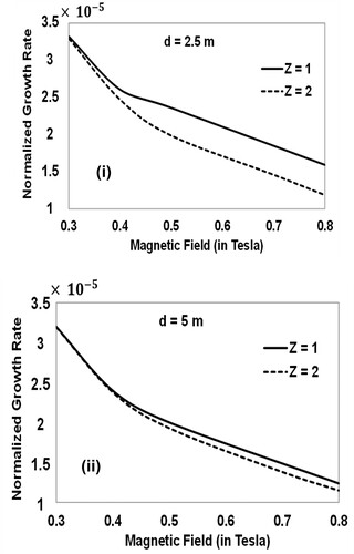
Figure 2. Normalized growth rate as a function of ion temperature gradient (in eV/m) for different values of x with (i) channel length (d) = 2.5 m and (ii) d = 5 m, when = 5 cm,
=
=
,
= 0.3 eV,
= 1.5 eV,
= 1.6. kg,
=
m/s,
=
m/s, Z = 1 and B = 1 T.
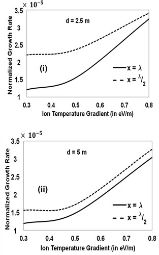
Figure 3. Normalized growth rate as a function of ion temperature (in eV) for different electron temperature in eV with (i) channel length (d) = 2.5 m and (ii) d = 5 m when
= 5 cm, x =
,
=
=
,
= 1.6. kg,
=
m/s,
=
m/s, Z = 1, B = 1 T and
= 1 eV/m.
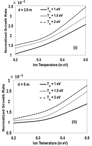
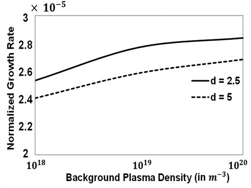
Figure 4. Normalized growth rate as a function of background plasma density (in ) for different channel lengths (d) when
= 5 cm, x =
,
= 0.3 eV,
= 1.5 eV,
= 1.6. kg,
=
m/s,
=
m/s, Z = 1, B = 1 T and
= 1 eV/m.
An equal temperature gradient is taken for both the species and hence, the normalized growth rate is plotted only as a function of the ion temperature gradient (in eV/m) in Figure . This is done for different values of x, i.e. at different positions in the channel as (i) channel length d = 2.5 m and (ii) d = 5 m. The magnitude of the growth rate is found to enhance with an increment in the ion temperature gradient. This can be seen from the basic relation (9) that the gradient reduces with increasing values of x from to
. Since the cause for the present instability is the gradient in the temperature as well as in the density, this is expected that the instability grows with higher rate for
. This is also an important observation that the difference in the magnitude of the normalized growth rate is decreased with the increasing gradient. Also, a small reduction in normalized growth rate is seen for the increased channel length from 2.5 m to 5 m, which confirms the results obtained in Figure .
The behaviour of normalized growth rate as a function of ion temperature (in eV) for different electron temperature in eV is studied through Figure with (i) channel length d = 2.5 m and (ii) d = 5 m. Larger growth rate is seen with the increased temperatures of both the ions and the electrons for both the cases of channel length. Also, a significant reduction in the magnitude of the normalized growth rate is recorded with an increased channel length from 2.5 m to 5 m.
Finally in Figure , we show the behaviour of normalized growth rate as a function of background plasma density (in ) for different channel lengths. Here, the magnitude of normalized growth rate is found to increase with the increased background plasma density, whereas it is reduced with the increased channel length. This confirms the results obtained in Figures , which also portrayed the reduction in normalized growth rate with the increased channel length. This can also be seen that the growth rate of the instability almost saturates for the much higher density. An early saturation takes place for the case of d = 2.5 in comparison to the case of d = 5. This is due to the stronger density gradient present in the system in the case of d = 2.5 that the instability grows with higher growth rate and also saturates early.
The above results show that the instability driven by the density gradient is very sensitive to the spatial variation of the ions and electrons temperature also. The instability does not grow at the same rate throughout the channel rather it depends on the position where one observes the same. The plasma density initially raises the growth of the instability at faster rate, after which the rate saturates. These results were obtained based on the linear analysis of the problem. However, computers (simulation) can do a greater job and provide the real scenario of the instabilities. This is also true that it becomes difficult to demarcate various instabilities while one uses the computer approach, but the present calculations can easily establish the regions for each kind of instability. The present calculations showed two types of the instabilities in the said system, but we plotted the results only for one kind of instability. Actually, the magnitude of the second kind of instability was very small in comparison to the discussed instability. Also, there were some propagating modes as per the dispersion equation (10), but their velocity was very small. For these reasons, we focused only on one instability and left the discussion on the others. Those small magnitude modes and instabilities could be understood as only the noise in the system and are not expected to grow sufficiently.
As an application of the present model, we mention that the plasma is used in Hall thrusters [Citation6, Citation14, Citation32] and magnetic nozzle [Citation24, Citation33] for prolonged space propulsion/mission. Also, inductively coupled plasma along with such a cross field arrangement has been used for etching [Citation34–36], film deposition [Citation37–39] etc. in semiconductor industries. However, in these applications, only the electrons are magnetized which enhance the plasma production and hence, ultimately control the etching aspect ratio and film quality. Since our calculations have shown that such a plasma is susceptible to the instability if there are gradients in the density and temperature of the plasma species, in view of this the current model would enable the experimentalists to conduct experiments smoothly as they can keep the system away from the instabilities by generating plasma with the required properties.
4. Conclusions
Density gradient driven instability in an plasma system was explored numerically by assuming the finite temperature of both the plasma species, i.e. the ions and the electrons. All the calculations were performed by considering both the electrons and the ions to be magnetized. The magnitude of normalized growth rate was found to increase with an increment in the ion and the electron temperature and background plasma density, whereas it diminished with the increasing magnetic field strength and charge of the ions. The growth rate was also found to increase when the plasma has larger ion or electron temperature gradient. The dependence of plasma parameters on the growth rate for different channel length was also evaluated and a reduction in its magnitude was observed with the increased channel length.
Nomenclature
| = | External magnetic field | |
| = | Electronic charge | |
| E1 | = | Perturbed electric field |
| = | Wavenumber | |
| λ | = | Wavelength of oscillations |
| = | Electron mass | |
| = | Ion mass | |
| = | Electron density | |
| = | Background electron density | |
| = | Perturbed electron density | |
| = | Ion density | |
| = | Background ion density | |
| = | Perturbed ion density | |
| ω | = | Frequency of oscillations |
| ωe | = | Electron plasma frequency |
| Ωe | = | Electron cyclotron frequency |
| ωi | = | Ion plasma frequency |
| Ωi | = | Ion cyclotron frequency |
| = | Perturbed electric potential | |
| = | Electron temperature | |
| = | Ion temperature | |
| = | Electron velocity | |
| = | x-component of electron velocity | |
| = | y-component of electron velocity | |
| = | Ion velocity | |
| = | x-component of ion velocity | |
| = | y-component of ion velocity | |
| = | Ion charge |
Disclosure statement
No potential conflict of interest was reported by the author(s).
Additional information
Funding
References
- Boeuf JP. Tutorial: physics and modeling of Hall thrusters. J Appl Phys. 2017 Jan 7;121(1):011101.
- Choueiri EY. Plasma oscillations in Hall thrusters. Phys Plasmas. 2001 Apr;8(4):1411–1426.
- Zhurin VV, Kaufman HR, Robinson RS. Physics of closed drift thrusters. Plasma Sources Sci Technol. 1999 Feb 1;8(1):R1.
- Goebel DM, Katz I. Fundamentals of electric propulsion: ion and Hall thrusters. California Institute of Technology; 2008 Dec 22.
- Keidar M, Boyd ID. Effect of a magnetic field on the plasma plume from Hall thrusters. J Appl Phys. 1999 Nov 1;86(9):4786–4791.
- Malik HK, Tyagi J, Sharma D. Growth of Rayleigh instability in a Hall thruster channel having dust in exit region. AIP Adv. 2019 May 23;9(5):055220.
- Lafleur T, Baalrud SD, Chabert P. Characteristics and transport effects of the electron drift instability in Hall-effect thrusters. Plasma Sources Sci Technol. 2017 Jan 31;26(2):024008.
- Lazurenko A, Krasnoselskikh V, Bouchoule A. Experimental insights into high-frequency instabilities and related anomalous electron transport in Hall thrusters. IEEE Trans Plasma Sci. 2008 Oct 28;36(5):1977–1988.
- Litvak AA, Fisch NJ. Rayleigh instability in Hall thrusters. Phys Plasmas. 2004 Apr 26;11(4):1379–1383.
- Chable S, Rogier F. Numerical investigation and modeling of stationary plasma thruster low frequency oscillations. Phys Plasmas. 2005 Mar 10;12(3):033504.
- Malik HK, Singh S. Conditions and growth rate of Rayleigh instability in a Hall thruster under the effect of ion temperature. Physical Review E. 2011 Mar 15;83(3):036406.
- Hepner ST, Jorns B. The role of low frequency drift waves in driving non-classical transport in magnetic nozzles. InAIAA Propulsion and Energy 2020 Forum 2020 (p. 3644).
- Tsikata S, Cavalier J, Héron A, et al. An axially propagating two-stream instability in the Hall thruster plasma. Phys Plasmas. 2014 Jul 17;21(7):072116.
- Tyagi J, Singh S, Malik HK. Effect of dust on tilted electrostatic resistive instability in a Hall thruster. J. Theoretical Appl. Phys. 2018 Mar;12(1):39–43.
- Barral S, Ahedo E. Low-frequency model of breathing oscillations in Hall discharges. Phys Rev E. 2009 Apr 1;79(4):046401.
- Barral S, Peradzyński Z. Ionization oscillations in Hall accelerators. Phys Plasmas. 2010 Jan 13;17(1):014505.
- Meezan NB, Hargus Jr WA, Cappelli MA. Anomalous electron mobility in a coaxial Hall discharge plasma. Phys Rev E. 2001 Jan 24;63(2):026410.
- Thomas CA, Gascon N, Cappelli MA. Nonintrusive characterization of the azimuthal drift current in a coaxial E× B discharge plasma. Phys Rev E. 2006 Nov 15;74(5):056402.
- Kapulkin A, Guelman MM. Low-frequency instability in near-anode region of Hall thruster. IEEE Trans Plasma Sci. 2008 Nov 17;36(5):2082–2087.
- Sedighi HM, Ouakad HM, Dimitri R, et al. Stress-driven nonlocal elasticity for the instability analysis of fluid-conveying C-BN hybrid-nanotube in a magneto-thermal environment. Phys Scr. 2020 Apr 6;95(6):065204.
- Sedighi HM, Malikan M. Stress-driven nonlocal elasticity for nonlinear vibration characteristics of carbon/boron-nitride hetero-nanotube subject to magneto-thermal environment. Phys Scr. 2020 Mar 5;95(5):055218.
- Makinde OD, Adesanya SO, Ferdows M. A note on the hydromagnetic blasius flow with variable thermal conductivity. J Appl Comput Mech. 2020 Mar 30;7(4):1925–1930.
- Khurana M, Rana P, Srivastava S, et al. Magneto-bio-thermal convection in rotating nanoliquid containing gyrotactic microorganism. J Appl Comput Mech. 2021 Oct 1;7(4):1973–1986.
- Malik L, Kumar M, Singh IV. A three-coil setup for controlled divergence in magnetic nozzle. IEEE Trans Plasma Sci. 2021 Jun 25;49(7):2227–2237.
- Dhawan R, Malik HK. Sheath formation criterion in collisional electronegative warm plasma. Vacuum. 2020 Jul 1;177:109354.
- Dhawan R, Malik HK. Behaviour of sheath in electronegative warm plasma. J Theoret Appl Phys. 2020 Jun;14(2):121–128.
- Dhawan R, Malik HK. Sheath characteristics in plasma carrying finite mass negative ions and ionization at low frequency. Chin J Phys. 2020 Aug 1;66:560–572.
- Dhawan R, Kumar M, Malik HK. Influence of ionization on sheath structure in electropositive warm plasma carrying two-temperature electrons with non-extensive distribution. Phys Plasmas. 2020 Jun 15;27(6):063515.
- Malik L, Tevatia A. Comparative analysis of aerodynamic characteristics of F16 and F22 combat aircraft using computational fluid dynamics. Def Sci J. 2021 Mar 1;71(2):137–145.
- Malik L, Rawat S, Kumar M, et al. Simulation studies on aerodynamic features of eurofighter typhoon and dassault rafale combat aircraft. Mater Today: Proc. 2021 Jan 1;38:191–197.
- Pachauri S, Chaudhary J, Misra KP. Instabilities in magnetized inhomogeneous dusty plasmas with the effect of recombination. Plasma Res Exp. 2022 May 23;4(2):025004.
- Tyagi J, Sharma D, Malik HK. Discussion on Rayleigh equation obtained for a Hall thruster plasma with dust. J Theoret Appl Phys. 2018 Sep;12(3):227–233.
- Malik L. Tapered coils system for space propulsion with enhanced thrust: A concept of plasma detachment. Propulsion Power Res. 2022 Jun 1;11(2):171–180.
- Shul RJ, McClellan GB, Casalnuovo SA, et al. Inductively coupled plasma etching of GaN. Appl Phys Lett. 1996 Aug 19;69(8):1119–1121.
- Parker ER, Thibeault BJ, Aimi MF, et al. Inductively coupled plasma etching of bulk titanium for MEMS applications. J Electrochem Soc. 2005 Aug 12;152(10):C675.
- Rawal DS, Malik HK, Agarwal VR, et al. BCl3/Cl2-based inductively coupled plasma etching of GaN/AlGaN using photoresist mask. IEEE Trans Plasma Sci. 2012 Aug 6;40(9):2211–2220.
- Li J, Kim SJ, Han S, et al. Characterization of sp2/sp3 hybridization ratios of hydrogenated amorphous carbon films deposited in C2H2 inductively coupled plasmas. Surf Coat Technol. 2021 Sep 25;422:127514.
- Kumar S, Malik A, Rawal DS, et al. Performance analysis of GaN/AlGaN HEMTs passivation using inductively coupled plasma chemical vapour deposition and plasma enhanced chemical vapour deposition techniques. Def Sci J. 2018 Nov 1;68(6):572–576.
- Kumar S, Rawal DS, Malik HK, et al. Memory effect in silicon nitride deposition using ICPCVD technique. J Theoret Appl Phys. 2019 Dec;13(4):299–304.