
 ?Mathematical formulae have been encoded as MathML and are displayed in this HTML version using MathJax in order to improve their display. Uncheck the box to turn MathJax off. This feature requires Javascript. Click on a formula to zoom.
Abstract
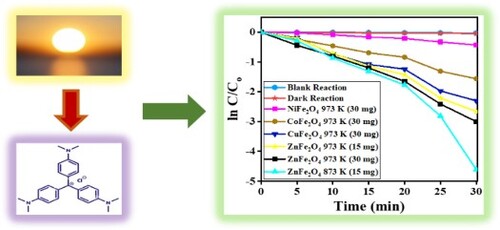
Using the co-precipitation oxidation method and metal salt precursors, pure MFe2O4 (M = Co, Zn, Cu and Ni) photocatalysts were prepared co-precipitation method. The several properties of photocatalysts were studied. In sunlight and at neutral pH, all photocatalysts degraded crystal violet and performance ranking was NiFe2O4 < CoFe2O4 < CuFe2O4 < ZnFe2O4. Among these photocatalysts, ZnFe2O4 showed the highest photocatalytic degradation performance due to the smallest particle sizes, which were widely distributed. More channels were obtained due to the small pore volume providing a high number of active sites with optical band gap values of 1.69–2.55 eV. The photocatalytic degradation was an effect of the ratio of Zn/Fe, photocatalyst loadings, and calcination temperature. Calcination time and reaction duration were studied. The photocatalytic degradation reaction was almost completed within 24 h using Zn:Fe (1:2). The reaction followed the first-order rate constant. Photocatalysts were stable for seven times recycles.
GRAPHICAL ABSTRACT
1. Introduction
Over the past decade, water pollution and the energy crisis have motivated scientific researchers to utilize solar energy by using different techniques and designing various semiconductor materials to degrade toxic pollutants [Citation1,Citation2]. A significant concern is the pollution caused by hazardous dyes, which affects water bodies and the environment. The contaminants are non-biodegradable and toxic organic dyes produced by industries and disposed of improperly [Citation3,Citation4]. Among the most common culprit industries are fabric and textile, ink and printing, leather, pharmaceutical and food industries [Citation5,Citation6] and natural resources such as fossil fuels [Citation5].
There is a current need to tackle polluted environments. Numerous scientific studies and many visible-light-driven photocatalysts [Citation7] have been proposed and conducted to address this issue. To reduce the level of contaminants, eliminate pollutants and remediate wastewater containing uranium [Citation8], several processes and technologies, such as photocatalytic oxidation, membranes, adsorption, chemical oxidation and biodegradation [Citation7–10], have been evaluated for their pollution remediating capabilities. A promising approach to treating and purifying water using various metal oxide semiconductors is the process of heterogeneous photocatalysis in the presence of light [Citation11,Citation12].
Semiconductor-based photocatalysts are vital to significant, suitable and successful applications in degradation reactions due to their formation of the S-scheme, which can enhance photocatalytic performances and the excitation of electrons under sunlight irradiations [Citation1,Citation13,Citation14] and fast recombination for photogeneration of electrons and hole pairs. Firstly, the electron–hole will be migrated and separated on the surface of semiconductors, then, an oxidation–reduction reaction is initiated. An undesired situation for photodegradation reaction is the recombination of the electron–hole in the bulk of semiconductors before arriving at the surface [Citation13–15]. The intrinsic properties of these compounds lends themselves to photocatalysis, as their morphology, light absorption range, optical properties and particle sizes and hierarchical shapes are appropriate for the task [Citation16–18]. Some semiconductors have limitations on the remediation of pollutants due to their wide band gaps, so designing successful and suitable photocatalysts with narrow band gaps that can utilize visible light and improve photodegradation reactions is a considerable challenge [Citation1,Citation19]. Constructing a heterojunction of α-Fe2O4 with other semiconductors can successfully separate electron–hole pairs of fabricated semiconductors. For this purpose, Cr-doped SrTiO3/Ti-doped α-Fe2O3 photoanodes have been fabricated to enhance the photoelectrochemical properties [Citation20]. To attain the advantages of using low energy consumption and sustainable energy from solar light resources with milder conditions, the metal organic framework-derived (MOFs) porous Fe2O4 nanostructures were used for pyridine denitrification for the first time. The high rate of photocatalytic reaction was superior due to the visible light absorption of Fe2O3, its porosity for fast transportation of electrons, and the role of an organic framework in improving the separation and transformation of photogenerated electron–hole pairs [Citation18]. Due to the chemical, electrical and mechanical properties, together with their high activity, low cost, magnetism, selectivity and capacity to be readily separated from media, high thermal MFe2O4 are attractive photocatalysts [Citation21,Citation22]. These materials of photocatalysts have been recognized as valuable and effective for cleaning the environment by photodegrading harmful organic pollutants with the aid of photoenergy [Citation23]. They were expected to be utilized with solar energy to provide hydrogen fuels by splitting water [Citation24–27]. Recent scientific research has evaluated photocatalytic H2 as clean and sustainable energy with a high thermal value [Citation24]. For that purpose, several photocatalysts of MoS2@ZnxCd1−xS [Citation25], CoFe2O4@ZnS core–shell [Citation26] and NiCo2O4@ZnS [Citation27] were used for converting solar energy into renewable hydrocarbon fuels by reducing CO2 and the evaluation of clean energy, such as H2, performance from water splitting. These materials have been reported as having high electronic charge transportation, suitable band gaps and excellent absorption of visible light [Citation28]. The rates of photocatalytic reaction of H2 evaluation were improved by the applied calcination temperature and the morphology of prepared photocatalysts [Citation26], which display excellent nonstructural qualities and offer unique potential for use as semiconductor photocatalysts [Citation25–29]. The nanocomposite of ZnFe2O4@TiO2/Cu was an efficient photocatalyst in sunlight photodegradation of naproxen with 80.73% photodegradation. However, photodegradation was decreased by increasing the flow rate of naproxen from 5 to 15 mL/min [Citation30]. It has been reported that the GO/NiFe2O4/TiO2 composite photocatalyst was active in removing unsymmetrical dimethylhydrazine from wastewater under visible light due to its electron and hole being well separated [Citation13].
ZnFe2O4 nanostructures are considered to be the significant features that determine how ZnFe2O4 can be suitably applied. Enhancing the particle size Zn with Fe composites could optimize photocatalytic functionality [Citation31–33].
Using the citrate method to synthesize Zn-Co/Fe photocatalysts, Chahar et al. [Citation34] varied the proportions of Zn and Co. The photodegradation functionality of these compounds was evaluated; as the ratio of Co to Zn increased, the ability of photocatalysts to degrade methylene blue in sunlight increased.
Based on the above contents, MFe2O4 (M = Zn, Co, Cu and Ni) were synthesized for sunlight-efficient photocatalysts in this research work. In addition, these materials were characterized, and their photocatalytic performance was evaluated by the photodegradation of crystal violet (CV) dye under solar irradiation. For further studies, the dosage, duration, calcination temperature and reusability of the most effective photocatalysts were determined to establish their optimal functional conditions and the possible mechanism was investigated.
2. Experimental
2.1. Materials
To prepare CoFe2O4, CuFe2O4, NiFe2O4 and ZnFe2O4 photocatalysts, the precursor materials CoCl2.6H2O, CuSO4.5H2O, NiCl2.6H2O, Zn(NO3)2.6H2O, Fe(NO3)3.9H2O and NaOH were purchased from Sigma-Aldrich, whilst p-toluene sulfonic acid (C7H8O3S.H2O) was purchased from Loba Chemie Pvt Ltd. Photocatalytic degradation reactions were conducted using CV dye from BHD as the dye model. For synthesizing the photocatalysts and dye solution, distilled water was used. As the reagents were of analytical grade purity, they were used without purifications.
2.2. Photocatalysts preparation procedures
In this study, MFe2O4 photocatalysts were prepared by the surfactant-mediated co-precipitation method. The synthesis processes and the molarities of the metal salt amounts were used as written in the previous literature [Citation35,Citation36]. An appropriate quantity of precursors was weighted with an optimized molar ratio. Then the precursors were separately dissolved in distilled water before being combined in a beaker and stirred for 10 min. The mixture was heated on a hot plate to 338–343 K and stirred constantly [Citation37]. To this, 1 g of p-toluene sulfonic acid was added; then the mixture was stirred for 30 min. To obtain the precipitate, 1 M of NaOH solution was added dropwise. The reaction continued until 12 pH [Citation35]; then the mixture was left in the same conditions to mature for one hour. After cooling the precipitate to room temperature, it was then filtered and rinsed a number of times using distilled water. The resulting powders were oven-dried overnight at 383 K before being calcined at 773–1173 K for 3–24 h, using a heating rate of 283 K/min [Citation38].
2.3. Instrumental techniques
X-ray diffraction (XRD) with the model of Bruker D8 advanced powder diffractometer was used to measure the MFe2O4 solid crystal structures and their phases. XRD patterns were established using Cu-Kα radiation (λ = 1.5416 Å) in the 0.2θ scale range of 10°–80° and scanning step of 0.2° at 45 kV and 40 mV. Fourier transform infrared (FT-IR) Spectrometry with equipment model of PerkinElmer Spectrum 100 was used to identify and verify the functional group in the prepared composite metal oxides. The KBr method was used in the range of 400–4000 cm−1. Scanning electron microscopy (SEM), the Hitachi S-4800 (Tokyo, Japan) and the JEOL JEM-2100F of high-resolution transmission electron microscopy (TEM) were used to explore the morphological characteristics of the compounds. UV-Vis spectrophotometry (Philips 8800) was performed to measure the band gaps and degradation reactions of the photocatalysts. The Brunauer–Emmett–Teller (BET) with Micromeritics Tristar II 3020 analyser equipment model was used for measuring the specific surface area (SBET), and the porosity of each sample was obtained by the Barrett-Joyner-Halenda (BJH) method.
2.4. Preparation of CV dye solution
To prepare the CV dye, 10 mg of dye was dissolved in 1 L of distilled water to yield 10-ppm. The volumetric flask containing the solution was covered and stored in a dark room until required to prevent photocatalytic reactions.
2.5. Photocatalytic degradation of CV dye procedure
CV dye was photocatalytically degraded in a quartz beaker using batch reactor in sunlight at neutral pH; different dosages of photocatalysts were used. The dose of photocatalyst was added to 20 ml of 10 ppm of CV dye solution. The mixture was allowed to reach equilibrium by keeping it in a dark room for 20 min. Then the mixture taken into the courtyard of the King Saud University to be exposed to solar irradiation (it was a sunny day) for the optimized duration. The reactions were started between 11: 30 am and 2:00 pm, when the temperature was 308–321 K and the intensity of sunlight was 0.015–0.025 W/m2. The duration of the reaction was between 5 and 30 min. At the end of the reaction duration, the mixture was centrifuged to isolate the photocatalyst from the mixture. For each reaction time, the absorbance of clear solution of product was measured at 587 nm by using UV-Vis spectrometry, from which the percentage of CV dye solution degradation was determined. Equation (1) was used to calculate the percentage of photodegradation [Citation39,Citation40].
(1)
(1)
where, Ao is the initial absorbance of dye and At denotes the variable absorbance of CV dye at different reaction time.
3. Results and discussion
3.1. Structural properties
The XRD patterns for the samples of MFe2O4 are presented in Figure . With pure spinel MFe2O4 nanocomposites, strong, sharp peaks are evident. JCPDS cards were used: no. #22-1086 for CoFe2O4, # 22–1012 for ZnFe2O4, #34-0425 for CuFe2O4, 10–0325 for NiFe2O4 and #87–1166 for α-Fe2O3 phase. The phases have (1 1 1), (2 2 0), (3 1 1), (2 2 2), (4 0 0), (4 2 2), (5 1 1) and (4 4 0) of h k l values for ZnFe2O4, CoFe2O4 and NiFe2O4. The CuFe2O3 has (1 0 1), (1 1 2), (2 1 1), (2 0 2), (2 2 0), (3 1 2), (3 2 1) and (2 2 4) [Citation35]. Only the NiFe2O4 nanocomposite exhibited Fe2O3 impurity; the other photocatalysts were uncontaminated. X-ray results reveal all the materials to be monocrystalline and nanocrystallines with face-centered cubic structures.
Figure 1. XRD patterns of the MFe2O4 nanocomposite photocatalysts.
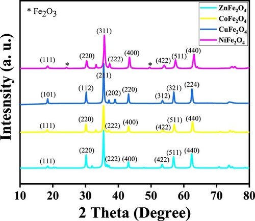
Using the Debye-Scharrer equation, the size of monocrystalline MFe2O4 nanocomposites was calculated; the calculation was based on the maximal peak intensity, which appears at 35.74 of θ. With the value of h k l are 3 1 1. The crystalline size (d) can be calculate using the formula (d) = 0.9λ/β cos θ, where λ is (Cu Kα = 0.154 nm), which is the wavelength of X-ray diffraction, β is the full width at the half of the intense peak in the radian unit and θ is the Bragg angle of the peak intensity. shows that the crystal sizes of ZnFe2O4, CoFe2O4, CuFe2O4 and NiFe2O4 were 21.71, 21.69, 18.30 and 23.86 nm, respectively, and they were smaller than previous results reported by Gupta et al. [Citation35]. The crystalline size and interplanar spacing of photocatalysts are consistent with the results of the TEM analyses (). The results of interplanar spacing showed that the spacing was slightly smaller than the values previously reported. The decrease of the values of prepared materials in this study is due to their smaller crystalline sizes.
Table 1. Crystalline, interplanar spacing, particle sizes and lattice constant of MFe2O4 nanostructures calcined at 973 K for 24 h.
The highest peak intensity was used to calculate the lattice constant of MFe2O4 nanomaterials. The following equation was used: Lattice constant (a) = dhkl (h2 +k2 +l2)1/2, where, d is the inter planar distances, h k l is the Miller indices. presents the lattice constants, nanoparticle and crystalline sizes of MFe2O4 samples [Citation37,Citation41].
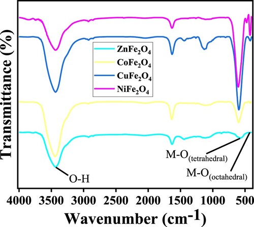
Figure presents the FTIR spectra of the MFe2O4 nanostructures. There are two distinct vibration bands for M-O at ν1 561.31–603.53 cm−1 and ν2 418.66–472.03 cm− 1. These reflect the stretching vibration of the M-O bond in the MFe2O4 spinel nanoparticles. The ν1 band reflects the stronger vibration modes of metal and oxygen in tetrahedral structures, whilst the lower band reflects the stretching vibration mode of oxygen and metal ions (Fe3+) in the octahedral structures. The masses of the cations and the distances between M+n and O2− influence the vibration frequencies of the complexes of tetrahedral and octahedral forces. The stretching vibration of O-H manifests as the broad bands at 3434.73–3435.69 cm−1. The weak intensity peaks at 1630.36–1632.90 cm−1 are attributed to the O-H bending modes due to water molecules adsorbed the surface of MFe2O4 [Citation42,Citation43]. FTIR was used to verify the spinel structures of all of the MFe2O4 samples evaluated in this study (Figure ).
Figure 2. FT-IR spectra of MFe2O4 nanocomposite photocatalysts, calcined at 973 K for 24 h.
3.2 Morphological properties
SEM, EDS and TEM were used to explore the morphology, particle size and structural properties of all of the MFe2O4 photocatalysts; results are shown in Figures .
Figure 3. SEM images of (a) NiFe2O4; (b) CoFe2O4; (c) CuFe2O4; (d) ZnFe2O4, calcined at 973 K for 24 h.
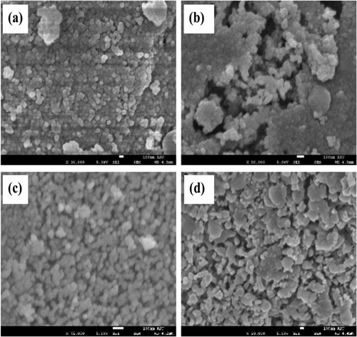
Figure 4. EDS analysis of (a) NiFe2O4; (b) CoFe2O4; (c) CuFe2O4; (d) ZnFe2O4, calcined at 973 K for 24 h.
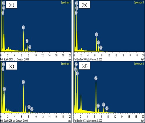
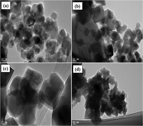
Figure 5. HRTEM results and particle size distributions of (a) NiFe2O4; (b) CoFe2O4; (c) CuFe2O4; (d) ZnFe2O4, calcined at 973 K for 24 h.
To obtain a clearer view of the photocatalysts surface morphology, SEM was used. This revealed the different types of nanoparticles to be distinct, but within their own type, their spherical-like structures are homogenous. All of the MFe2O4 samples were evenly sized and nearly spherical. The SEM results for ZnFe2O4 calcined at 973 K show that compared to other samples, these photocatalysts formed agglomerations of highly organized, uniformly sized spherical particles (Figure (d)). These features might contribute to the photocatalytic degradation activity of this sample. Due to the low magnification of the SEM, it was difficult to measure the size of the four types of photocatalytic nanoparticles reliably [Citation39].
Figure shows the results of EDS for all photocatalysts prepared in this study. The respective percentages of these elements are 55.68%, 27.69% and 16.63% in the NiFe2O4, 64.08%, 23.71% and 12.21% in the CoFe2O4, 50.67%, 35.08% and 14.25% in the CuFe2O4 and 49.26%, 32.24% and 18.50% in the ZnFe2O4. The EDS data and XRD analysis confirmed the presence of MFe2O4 nanocomposites (see section 3.1).
From the EDS results, it is clear that the prepared samples contained Fe, Co, Cu, Ni and Zn. Figures (a–d) depict the MFe2O4 structures, which were confirmed in each sample at their corresponding of energy of keV values. The peaks of M, Fe and O indicate the absence of impurities.
High resolution TEM images were acquired and used to assess the grain size, morphology and size distribution of the four types of photocatalysts prepared (Figures (a–d)). The results reveal evenly formed nanostructures with nanoparticles of different sizes.
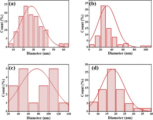
The morphology of the photocatalytic nanoparticles was spherical and even. Figures (a-d) show the particle size distributions of NiFe2O4, CoFe2O4, ZnFe2O4 and CuFe2O4. The average particle sizes of the photocatalysts are presented in . It shows that at 32 nm, the largest nanoparticle was CoFe2O4, whilst ZnFe2O4 was the smallest particle (18 nm). This feature could contribute to the ability of photocatalysts to degrade CV dye. Figure (a) shows the agglomeration of NiFe2O4 was greater than the agglomeration of other photocatalysts. ZnFe2O4 has the lowest agglomeration, and the particle sizes are distributed well with the smallest diameter value, as Figure (d) shows. A comparison of pore diameters show that CuFe2O4 > CoFe2O4 > NiFe2O4 > ZnFe2O4; this finding is consistent with the XRD results (). Thus, ZnFe2O4 morphology could support the compound's ability to photodegrade CV dye.
Figure 6. Particle size distributions of (a) NiFe2O4; (b) CoFe2O4; (c) CuFe2O4; (d) ZnFe2O4, calcined at 973 K for 24 h.
3.3. Textural properties of MFe2O4
It is well-known that photocatalysts’ surface area and pore size play a vital role in photocatalytic degradation reaction activity [Citation37]. The BET plots and BJH pore size distributions of MFe2O4 photocatalysts are presented in Figure . shows a summary of the textural properties of surface area and that porosity for MFe2O4 photocatalysts were calcined at 873 and 973 K.
Figure 7. Nitrogen adsorption-desorption isotherms and pore size distribution of MFe2O4 photocatalysts.
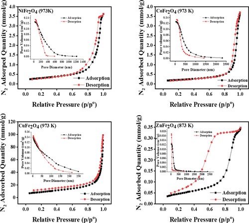
Table 2. Textural properties of MFe2O4 nanoparticles.
The isotherms of CuFe2O4, NiFe2O4, CoFe2O4 and ZnFe2O4 calcined at 973 K have IV type. The results show that all the photocatalysts have mesoporous hysteresis loops [Citation44], except CuFe2O4, which has a microporous hysteresis loop [Citation45]. ZnFe2O4 was calcined at 873 and had a H2 hysteresis isotherm with a non-uniform size of nanoparticles. This type of hysteresis confirmed that the pores of photocatalysts have differing sizes, and display different behaviours regarding adsorption–desorption pore sizes.
It has been reported that this type of H2 hysteresis is present in many common mesoporous materials. Photocatalytic degradation activity can be enhanced by mesoporosity structures [Citation44]. In this case, the photocatalytic degradation reactions have not been affected by the surface area of photocatalysts. Among synthesized photocatalysts, ZnFe2O4 has a smaller pore volume, indicating that this material has smaller grain sizes. Several channels provided a high number of active sites or contact locations on the surface of ZnFe2O4 that were enhanced by the photocatalytic degradation of CV dye.
3.4. Optical properties
The amount of light that photocatalysts absorb is determined by their band gap energies, which is the difference between the conduction and valance bands [Citation37,Citation39]. Figure shows the optical properties of ZnFe2O4, CoFe2O4, CuFe2O4 and NiFe2O4, summarized in . The optical properties are informed the significant information due to their photocatalytic activities. UV-Vis spectrometry was used to measure the band gaps, which was performed at room temperature. The following formula was used to calculate the band gaps energies of the photocatalysts: λmax = 1240/Eg, where, λmax is the maximum wavelength and Eg is the band-gap energy [Citation39]. The band gaps were as followings ZnFe2O4 = 2.55 eV, CoFe2O4 = 2.40 eV, CuFe2O4 = 2.48 eV and NiFe2O4 = 2.53 eV. ZnFe2O4 and the value of band gaps of prepared photocatalysts are consistent with the study conducted by Gupta et al. [Citation35].
The optical band gap energy was also measured as Figure and show. It is well known that the optical band gap energy can be calculated by using the following equation [Citation31,Citation37]:
(2)
(2)
where, hν is the photon energy; A is the light absorbance; B is the constant related to materials, and n can be
or 2 for direct or indirect transitions, respectively. To obtain the band gaps for all prepared photocatalysts, the linear proportion of the (Ahν)n – hν extrapolated the curve to zero [Citation39,Citation42]. Figure shows the band gaps for prepared materials, corresponding to the visible light photo activity.
Tauc plots measured the band gaps and the results were 2.00–2.55, 2.53, 2.48 and 2.40 eV for ZnFe2O4, NiFe2O4, CuFe2O4 and CoFe2O4, respectively, as shown in Figure . The band gaps of photocatalysts are slightly different. The band gap value can be changed by the simulation and excitation of the electron from the valance to the conduction band. It has been reported that the semiconductor of Fe2O4 has a narrow band gap. If combined with a wide band gap semiconductor such as ZnO, the resulting composite band gap can improve the performance of photodegradation reactions better than ZnO alone. ZnFe2O4 has an optical band gap value of 2.00–2.55, higher than other semiconductors in this study due to the wide ZnO band gap [Citation12].
3.5. Evaluation of photocatalytic activity
The rationale for using CV dye as the model dye is that the textile industry commonly uses it. The CV dye enabled assessment of the photocatalysts degradative performance in neutral pH solution and in sunlight. The performance of the different types of photocatalysts evaluated by investigating in detail the optimal ratio of Zn/Fe, calcination temperature, calcination duration, the dosage of photocatalyst and the duration required for the dye to photodegrade.
The graph in Figure plots the percentage of photocatalytic degradation of CV dye against duration. Conditions were 30 mg of photocatalyst, 10 ppm of dye, sunlight and neutral pH. The respective percentages of photodegradation for NiFe2O4, CoFe2O4, CuFe2O4 and ZnFe2O4 calcined at 973 K were 35%, 79%, 93% and 96%. Although ZnFe2O4 was slightly more active than CuFe2O4, the CV dye degradation by ZnFe2O4 and CuFe2O4 were similar in their effectiveness. Based on the size of ZnFe2O4 nanoparticles, these photocatalysts showed the best photodegradation of CV dye. Compared to the other photocatalysts used in this study, at 18 nm, the size of ZnFe2O4 nanoparticles was the smallest.
The photodegradation activity of NiFe2O4 was the lowest of the four types of photocatalysts. The formation of hematite (α-Fe2O3) can be affected by the photocatalytic degradation performances because the α-Fe2O3 impurity might act as a charge carrier centre. The recombination of photogenerated hole–electron pairs was increased and the carrier mobility of NiFe2O3 was decreased [Citation46]. Meanwhile, the CoFe2O4 exhibited a moderate capacity to photocatalyse CV dye. The elevated catalytic activity of ZnFe2O4 is attributed to its porous morphology and homogeneity. The effectiveness of ZnFe2O4 was demonstrated as 0.5 mg of the photocatalyst in 5 mmol of H2O2 almost completely degraded 10 ppm of methylene blue in 5 min [Citation35].
Inspired by these results, the effect of modifying the ratio of Zn to Fe was explored further. Then the most effective ratio of ZnFe2O4 was used for further study. The duration and temperature of calcination, and the amount of photocatalyst were investigated in detail at the same conditions of photodegradation of the CV dye.
The effect of calcination upon the photocatalytic degradation of CV was explored by calcining this photocatalyst at different temperatures ranging from 773 K to 1173 K. These samples were then evaluated by exposing them to CV dye and sunlight. The extent of photodegradation achieved by calcining ZnFe2O4 (1:2) at different temperatures is shown in Figure (a). According to the results, the photocatalytic degradation increased when the calcination temperature was 773–873 K; however, when the calcination temperature was 973–1073 K, photodegradation of CV dye declined slightly. At a calcination temperature of 1173 K, the dye degradation capability of ZnFe2O4 declined sharply. It is possible that at the higher temperature, there was sintering of the photocatalyst. The optimal calcination temperature was 873 K. Photocatalysts were calcined for different durations of 3 h to 24 h (Figure (b)).
The calcination experiments revealed that samples calcined for 24 h were the most effective at degrading CV dye. These conditions of calcination temperature and calcination times were applied for further studied of ZnFe2O4 as in the following sections. The maximum photocatalytic degradation, which was ≈100%, occurred with samples that had been calcined at 873 K for 24 h. Evidently, the calcination duration and temperature influence the rate at which the dyes are degraded. The reason for that because at higher temperature the catalytic agglomeration was affected on the catalytic performance [Citation39].
Figure (a and b) shows the effect of loading of photocatalysts and the ratio Zn/Fe and the loading of photocatalysts. Using different ratios of Zn/Fe upon the photocatalytic degradation of CV dye. ZnFe2O4 was prepared with different Zn:Fe ratios (1: 0.5. 1:1, 1:2, 1:3. 1:4 and 1:5), along with pure ZnO and pure Fe2O4 nanoparticles. Their ability to photodegrade CV dye for 30 min was evaluated. In this series, the ratio of 1:2 was the most effective photocatalyst. With 15 mg of photocatalyst and 10 ml of 10 ppm of CV dye, 91% of the dye was photodegraded in sunlight and at neutral pH. It can be seen that, the composition of Zn and Fe gave the best photocatalytic degradation in comparison to pure ZnO and pure Fe2O4 separately (Figure (a)). As stated earlier, these low-cost photocatalysts are easy to prepare, yet they possess high photocatalytic activity, able to photodegrade organic dyes that are significant pollutants present in wastewater. The Zn:Fe ratio significantly influences the properties of ZnFe2O4 photocatalysts [Citation35,Citation47].
Figure 8. UV-Vis absorption spectra of MFe2O4 nanostructures.
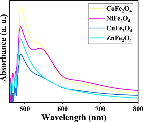
Figure 9. Plots of (Ahν)n as a function of photon energy (hν).
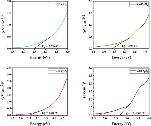
Figure 10. Photodegradation vs time of MFe2O4, calcined at 973 K for 24 h.
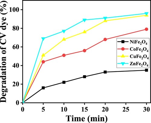
Figure 11. (a) Effect of calcination temperature of ZnFe2O4. (b) Effect of calcination duration upon photocatalytic activity of ZnFe2O4 (1:2) nanoparticles calcined at 873 K on the photodegradation of CV dye using 15 mg of photocatalyst, 10 ml of 10-ppm CV solution in sunlight and pH 7.
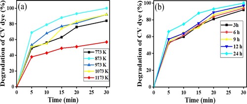
Figure 12. (a) effect of ratio of Zn/Fe, (b) effect of load of ZnFe2O4 (1:2) nanoparticles calcined at 873 K on the photodegradation of CV dye using 15 mg of photocatalysts, 10 ml of 10 ppm CV solution under sunlight radiation and at pH 7 for 30 min.
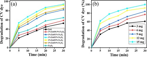
To evaluate the effect of dose upon photocatalytic activity, 3, 6, 9, 12 and 15 mg doses of ZnFe2O4 with 1:2 ratio and calcined at 873 K for 24 h were evaluated. The photocatalytic reaction was allowed to run 30 min; the dose with the most effective photocatalytic performance was 15 mg. Photocatalytic degradation increased as the dose of catalyst was increased due to the available and favourable active sites for electron separation and the formation of reactive oxygen species which accelerated the rate of photocatalytic degradation of dye [Citation44]. This study found that optimal photocatalytic conditions were achieved with 1:2 Zn:Fe calcined at 873 K for 24 h as Figure (b) represents. This is consistent with the findings of Gupta et al. [Citation35]. Under these conditions, CV was entirely degraded (100%).
Figure (a and b) displays the time-dependent photocatalytic degradation plots of the CV dye in the dark and blank reactions. It can be said that only slight degradation has been noted in the dark reaction, and the value of degradation (%) for blank and dark reactions were 2.8% and 4%, respectively, in agreement with the findings reported by Bayahia [Citation39]. In the presence of ZnFe2O4 (1:2), calcined at 873 and 973 K for 24 h with 15–30 mg doses of photocatalyst, as Figure (c and d) shows. The photocatalytic degradation reactions under sunlight irradiation increased considerably. As the reaction duration extended, the amount of dye photodegradation concomitantly increased. The photodegradation activity of ZnFe2O4 calcined at 973 K was lower than the samples calcined at 873 K. This is attributed to the size of their nanoparticles (see ). The extent of CV dye photodegradation in sunlight is significantly influenced by the calcination duration and temperature, the ratio of Zn:Fe and the dose of photocatalyst.
Figure 13. Time-dependent spectral changes to CV dye solution (a) dark reaction catalyzed by ZnFe2O4, calcined at 973 K; (b) blank reaction; (c) catalyzed reaction by ZnFe2O4, calcined at 873 K; (d) catalyzed reaction by ZnFe2O4, calcined at 973 K.
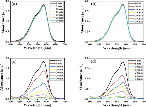
The observed maximum photocatalytic efficiency was achieved by exposing the dye to ZnFe2O4 for 30 min in sunlight. The reasons for that might be according to the effective separation, productions of electron and hole might be inhibited, the optical band gaps, the average particle size and the active scavenger number might be more created by using by ZnFe2O4 photocatalyst. The large band gap might photo induce the electron–hole pair, which in turn initiates more places of charge carries for efficiency oxidation of CV dye.
As the duration of solar irradiation increased in the presence of photocatalysts, the concentration of CV dye decreased (Figure (c and d)). Although all the photocatalysts investigated in this study were able to photodegrade CV dye, the most effective photocatalyst was ZnFe2O4 that had been calcined at 873 K for 24 h.
The kinetics reaction of photocatalytic degradation of CV dye followed first-order reaction dynamics. This was established by using the following equation [Citation32,Citation37,Citation48]:
(3)
(3)
where Co and Ct is the concentration of CV dye at time = 0 and irradiation solar light time (t) respectively and kapp is the rate constant, which is obtained from the slope of the ln(Ct/Co) against t plot, and t is the time of exposure of sunlight.
The plot in Figure (a and b) shows a straight line, which is consistent with a first-order reaction. The reaction rate of ZnFe2O4 calcined at 873 K is three times faster than ZnFe2O4 calcined at 973 K. The difference in the reaction rate is attributed to the rapid recombination of the electron–hole pair affecting the photodegradation of the CV dye [Citation41]. The kapp and t1/2 are summarized in .
Figure 14. (a) C/Co vs time plot for the photocatalytic degradation of CV dye, and (b) the plot of ln (C/Co) vs time for the kinetic study by MFe2O4 photocatalysts.
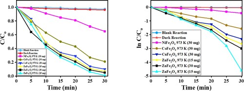
Table 3. Kinetic studies of photocatalytic degradation of CV dye using MFe2O4 nanostructures.
3.6. Reusability reactions of ZnFe2O4 for photodegradation of CV
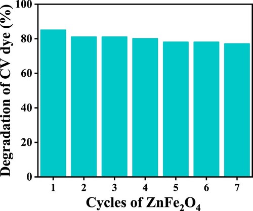
To test the reusable efficiency of ZnFe2O4, each cycle of dye degradation was measured. After each cycle, used photocatalyst was isolated from the reaction mixture, rinsed in distilled water several times and once by acetone, then oven-dried at 423 K for 24 h. The revitalized photocatalyst was reused to photodegrade CV dye.
As shown in Figure , at first use, the ZnFe2O4 photocatalysts degraded ≈100% of the CV dye. However, after revitalizing the photocatalysts, efficiency declined with the second and third use, falling to 81%. The findings of the reusability studies are consistent with those reported by Bayahia [Citation39]. After first use of the photocatalyst, the efficiency of reused ZnFe2O4 declined with each consecutive run to be 85%, 81%, 81%, 80%, 78%, 78% and 77% from run one to run seven, respectively.
Figure 15. Degradation efficiency ZnFe2O4 per run, measured as the percentage of CV dye degraded by photocatalysts.
3.7. Reaction mechanism of photodegradation of CV over MFe2O4
The valence band of ZnFe2O4 was determined by using the valence band XPS spectra. As shown in Figure (a), the valence band was found to be 1.05 eV; the energy gap between the valence band of ZnFe2O4 and the conduction band of ZnFe2O4 was determined via DRS spectra and found to be 2.01–2.55 eV. Conversely, the Mott–Schottky plots of ZnFe2O4 have been illustrated in Figure (b). ZnFe2O4 is a p-type semiconductor. According to the intersection of the linear potential curve, the flat band potentials (Efb) of about −1.44 and −0.98 eV versus an NHE electrode for ZnFe2O4 samples. Since the EFB is considered approximately as the conduction band (CB), the energy positions of the valence band edge (EVB) can be calculated according to the following equation [Citation16,Citation17,Citation41]:
(4)
(4)
where Eg is the band gap of the ZnFe2O4, the E(VB) of the ZnFe2O4 was estimated to be 1.28 and 1.2 V, respectively, as shown in Figure (c).
Figure 16. (a) XPS spectra; (b) Mott–Schottky plots; (c) scheme of energy with reduction potentials vs. NHE of ZnFe2O4 photocatalyst.
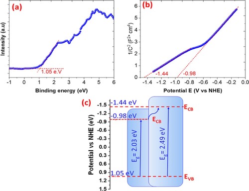
Figure 17. The rate of photocatalytic degradation of CV dye over ZnFe2O4 in the presence of active species.
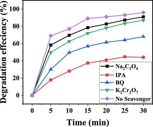
Figure shows the experiment of identifications of the main scavengers that were responsible for photocatalytic degradation of CV dye using ZnFe2O4 semiconductor. The different trapping agents were used. Different scavengers were used such as isopropyl alcohol (IPA), p- benzoquinone (BQ), sodium oxalate (Na2C2O4) and potassium dichromate (K2Cr2O7) for hydroxide radical (•OH), superoxide anion radical (•O2−), hole (h+) and electron (e−) respectively. The degradation performance was decreased in the order: IPA> BQ> K2Cr2O7 > Na2C2O4 > No scavenger. The addition of IPA wasdeacresed the photocatalytic degradation of CV dye by generating the •OH radicals. The •OH scavengers were the major active species for the photocatalytic degradation of CV dye. The photocatalytic degradation performance was decreased from 100% to
68% in the presence of BQ for 30 min in presence of ZnFe2O4 photocatalyst. The generation of •O2− radicals and the pairs h+/e− were the active species for the photocatalytic degradation in the presence of ZnFe2O4 photocatalyst that were irradiated under the sunlight [Citation35,Citation48].
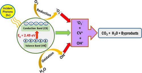
Based on the XPS, Mott-Sckotty and trapping study results, the degradation mechanism can be explained. Equations (5–9) postulate the mechanisms responsible for ZnFe2O4 photocatalytic activity. The hole–electron pairs are produced as the h+ in the valance band and ē in the conduction band in the ZnFe2O4 photocatalysts. The active species for the photocatalytic degradation of CV dye were the radicals of •OH anion and •O2−. These species were attacked the CV dye, yielding harmless carbon dioxide and water [Citation31,Citation49,Citation50].
The mechanism of photocatalytic degradation of CV over under sunlight irradiations was schemed and presented in Figure .
Figure 18. Scheme of the photocatalytic degradation mechanism of CV dye over ZnFe2O4 photocatalyst under sunlight irradiation.
(5)
(5)
(6)
(6)
(7)
(7)
(8)
(8)
(9)
(9)
4. Conclusion
This study explored the photocatalytic capability of MFe2O4 (where M = Zn, Co, Cu and Ni) to degrade CV dye. Photocatalysts were prepared using the surfactant-mediated co-precipitation method. The morphologies and textural and optical properties of the resulting photocatalysts were explored. The size particles ranged between 18 and 32 nm; meanwhile, the band gaps ranged from 1.69 eV to 2.55 eV. The photodegradation function of all the photocatalysts was evaluated against CV dye in conditions of sunlight and neutral pH. The effect of varying various parameters was explored, including modifying the ratios of Zn:Fe, the duration and temperature of calcination, and the dose of photocatalyst used. A 15 mg dose of ZnFe2O4 with a 1:2 ratio of Zn:Fe that had been calcined for 24 h at 873 K achieved 100% efficiency in photodegrading CV dye at a rate of 21.6 s−1. The excellent performance of ZnFe2O4 was due to its properties, which have the best-distributed particles with the smallest size and diameter. Furthermore, ZnFe2O4 was demonstrated as a stable photocatalyst and could be reused at least seven times.
Data availability statement
Not applicable.
Disclosure statement
No potential conflict of interest was reported by the author(s).
References
- Alharbi FF, Manzoor S, Munawar T, et al. Sunlight activated S-scheme ZnO-CoTe binary photocatalyst for effective degradation of dye pollutants from wastewater. Surf Inter. 2022;31:1–10. doi:10.1016/j.surfin.2022.101991.
- Alharbi FF, Aman S, Ahmad N, et al. Visible light active SrZrO3/PbS nanocomposite for photoconversion of CO2 into methane and methanol. Appl Phys A: Mater Sci Process. 2022;128(3):1–11. doi:10.1007/s00339-022-05383-6.
- Li X, Liu J, Huang J, et al. All organic s-scheme heterojunction PDI-Ala/S-C3N4 photocatalyst with enhanced photocatalytic performance. Wuli Huaxue Xuebao/ Acta Physico - Chimica Sinica. 2021;37(6):1–14. doi:10.3866/PKU.WHXB202010030.
- Soufi A, Hajjaoui H, Elmoubarki R, et al. Heterogeneous fenton-like degradation of tartrazine using CuFe2O4 nanoparticles synthesized by sol-gel combustion. Appl Surf Sci Adv. 2022;9:1–12. doi:10.1016/j.apsadv.2022.100251.
- Alburaih HA, Aadil M, Ejaz SR, et al. Wet-chemical synthesis of urchin-like Co-doped CuO: A visible light trigger photocatalyst for water remediation and antimicrobial applications. Ceram Int. 2022;48(15):21804–21813. doi:10.1016/j.ceramint.2022.04.159.
- Modi S, Fulekar MH. Synthesis and characterization of zinc oxide nanoparticles and zinc oxide/cellulose nanocrystals nanocomposite for photocatalytic degradation of methylene blue dye under solar light irradiation. Nano Environ Eng. 2020;5(18):1–12. doi:10.1007/s41204-020-00080-2.
- Shen R, Zhang L, Chen X, et al. Integrating 2D/2D CdS/α-Fe2O3 ultrathin bilayer Z-scheme heterojunction with metallic β-NiS nanosheet-based ohmic-junction for efficient photocatalytic H2 evolution. Appl Catal, B. 2020;266:1–9. doi:10.1016/j.apcatb.2020.118619.
- Dai Z, Zhen Y, Sun Y, et al. Znfe2o4/g-C3N4 S-scheme photocatalyst with enhanced adsorption and photocatalytic activity for uranium (VI) removal. Chem Eng J. 2021;415:1–10. doi:10.1016/j.cej.2021.129002.
- Charradi K, Ahmed Z, BenMoussa MA, et al. A facile approach for the synthesis of spinel zinc ferrite/cellulose as an effective photocatalyst for the degradation of methylene blue in aqueous solution. Cellulose. 2022;29(4):2565–2576. doi:10.1007/s10570-021-04334-3.
- He R, Chen R, Luo J, et al. Fabrication of graphene quantum dots modified BiOI/PAN flexible fiber with enhanced photocatalytic activity. Wuli Huaxue Xuebao/ Acta Physico - Chimica Sinica. 2021;37(6):1–9. doi:10.3866/PKU.WHXB202011022.
- Al Aqad KM, Basheer C. Photocatalytic degradation of basic blue dye using zinc nanoparticles decorated graphene oxide nanosheet. J Phys Org Chem. 2021;34:1–9. doi:10.1002/poc.4117.
- Liu D, Chen S, Li R, et al. Review of Z-scheme heterojunctions for photocatalytic energy conversion. Wuli Huaxue Xuebao/ Acta Physico - Chimica Sinica. 2021;37(6):1–31. doi:10.3866/PKU.WHXB202010017.
- Lu Y-B, Wang HC, She X-Y, et al. A novel preparation of GO/NiFe2O4/TiO2 nanorod arrays with enhanced photocatalytic activity for removing unsymmetrical dimethylhydrazine from water. Mater Sci Semicond Process. 2021;121:1–10. doi:10.1016/j.mssp.2020.105448.
- Wageh S, Al-Ghamdi AA, Jafer R, et al. A new heterojunction in photocatalysis: S-scheme heterojunction. Chin J Catal. 2021;42(5):667–669. doi:10.1016/S1872-2067(20)63705-6.
- Wang W, Zhao W, Zhang H, et al. 2D/2D step-scheme α-Fe2O3/Bi2WO6 photocatalyst with efficient charge transfer for enhanced photo-fenton catalytic activity. Chin J Catal. 2020;42(1):97–106. doi:10.1016/S1872-2067(20)63602-6.
- Puneetha J, Kottam N, Rathna A. Investigation of photocatalytic degradation of crystal violet and its correlation with band gap in ZnO and ZnO/GO nanohybrid. Inorg Chem Commun. 2021;125:1–12. doi:10.1016/j.inoche.2021.108460.
- Ameen S, Akhtar MS, Nazim M, et al. Rapid photocatalytic degradation of crystal violet dye over ZnO flower nanomaterial. Mater Lett. 2013;96:228–232. doi:10.1016/j.matlet.2013.01.034.
- Liang R, Liang Z, Chen F, et al. Article (special issue on photocatalytic H2 production and CO2 reduction) sodium dodecyl sulfate-decorated MOF-derived porous Fe2O3 nanoparticles: high performance, recyclable photocatalysts for fuel denitrification. Chin J Catal. 2020;41:188–199. http://www.sciencedirect.com/science/journal/18722067.
- Wang H, Li X, Zhao X, et al. A review on heterogeneous photocatalysis for environmental remediation: from semiconductors to modification strategies. Chin J Catal. 2022;43(2):178–214. doi:10.1016/S1872-2067(21)63910-4.
- Cao D, Zhang J, Wang A, et al. Fabrication of Cr-doped SrTiO3/Ti-doped α-Fe2O3 photoanodes with enhanced photoelectrochemical properties. J Mater Sci Technol. 2020;56:189–195. doi:10.1016/j.jmst.2020.04.025.
- Soufi A, Hajjoui H, Elmubaraki R, et al. Spinel ferrites nanoparticles: synthesis methods and application in heterogeneous fenton oxidation of organic pollutants – A review. Appl Surf Sci Adv. 2021;6:1–18. doi:10.1016/j.apsadv.2021.100145.
- Reddy DHK, Yun Y-S. Spinel ferrite magnetic adsorbents: alternative future materials for water purification? Coord Chem Rev. 2016;315:90–111. doi:10.1016/j.ccr.2016.01.012.
- George L, Viji C, Maheen M, et al. Synthesis, characterization of Mg/Mn substituted Ni-Zn ferrites and mechanism of their visible light photo catalysis of methylene blue and rhodamine B dyes under magnetic influence. Mater Res Express. 2020;7:1–18. doi:10.1088/2053-1591/ab5d26.
- Liang Z, Shen R, Ng YH, et al. A review on 2D MoS2 cocatalysts in photocatalytic H2 production. J Mater Sci Technol. 2020;56:89–121. doi:10.1016/j.jmst.2020.04.032.
- Wei Z, Xu M, Liu J, et al. Article (special issue on photocatalytic H2 production and CO2 reduction) simultaneous visiblelight-induced hydrogen production enhancement and antibiotic wastewater degradation using MoS2 @Znx Cd1-x S: solid solution-assisted photocatalysis. Chin J Catal. 2020;41:103–113. http://www.sciencedirect.com/science/journal/18722067.
- Chang CJ, Lee Z, Chu KW, et al. Cofe2o4@ZnS core–shell spheres as magnetically recyclable photocatalysts for hydrogen production. J Taiwan Inst Chem Eng. 2016;66:386–393. doi:10.1016/j.jtice.2016.06.033.
- Chang CJ, Lee Z, Wei MD, et al. Photocatalytic hydrogen production by magnetically separable Fe3O4@ZnS and NiCo2O4@ZnS core-shell nanoparticles. Int J Hydrogen Energy. 2015;40(35):11436–11443. doi:10.1016/j.ijhydene.2015.01.151.
- Shen R, Ren D, Ding Y, et al. Nanostructured CdS for efficient photocatalytic H2 evolution: A review. Science China Materials. 2020;63(11):2153–2188. doi:10.1007/s40843-020-1456-x.
- Bai J, Shen R, Chen W, et al. Enhanced photocatalytic H2 evolution based on a Ti3C2/Zn0.7Cd0.3S/Fe2O3 ohmic/S-scheme hybrid heterojunction with cascade 2D coupling interfaces. Chem Eng J. 2022;429:1–13. doi:10.1016/j.cej.2021.132587.
- Ahmadpour N, Sayadi MH, Sobhani S, et al. A potential natural solar light active photocatalyst using magnetic ZnFe2O4 @ TiO2/Cu nanocomposite as a high performance and recyclable platform for degradation of naproxen from aqueous solution. J Cleaner Prod. 2020;268. doi:10.1016/j.jclepro.2020.122023.
- Oliveira TP, Marques GN, Castro MAM, et al. Synthesis and photocatalytic investigation of ZnFe2O4 in the degradation of organic dyes under visible light. J Mater Res Techn. 2020;9:15001–15015. doi:10.1016/j.jmrt.2020.10.080.
- Qin M, Shuai Q, Wu G, et al. Zinc ferrite composite material with controllable morphology and its applications. Mater Sci Eng Bm. 2017;224:125–138. doi:10.1016/j.mseb.2017.07.016.
- Semeraro P, Bettini S, Sawalha S, et al. Photocatalytic degradation of tetracycline by ZnO/γ-Fe2O3 paramagnetic nanocomposite material. Nanomaterials. 2020;10:1–12. doi:10.3390/nano10081458.
- Chahar D, Taneja S, Bisht S, et al. Photocatalytic activity of cobalt substituted zinc ferrite for the degradation of methylene blue dye under visible light irradiation. J Alloys Compd. 2021;851:1–9. doi:10.1016/j.jallcom.2020.156878.
- Gupta NK, Ghaffari Y, Kim S, et al. Photocatalytic degradation of organic pollutants over MFe2O4 (M = Co, Ni, Cu, Zn) nanoparticles at neutral pH. Sci Rep. 2020;10(1):1–10. doi:10.1038/s41598-020-61930-2.
- Hirthna, Sendhilnathan S, Rajan PI, et al. Synthesis and characterization of NiFe2O4 nanoparticles for the enhancement of direct sunlight photocatalytic degradation of methyl orange. J Supercond Novel Magn. 2018;31(10):3315–3322. doi:10.1007/s10948-018-4601-3.
- Kalam A, Al-Sehemi AG, Assiri M, et al. Modified solvothermal synthesis of cobalt ferrite (CoFe2O4) magnetic nanoparticles photocatalysts for degradation of methylene blue with H2O2/visible light. Results Phys. 2018;8:1046–1053. doi:10.1016/j.rinp.2018.01.045.
- Nadeem N, Zahid M, Tabasum A, et al. Degradation of reactive dye using heterogeneous photo-fenton catalysts: ZnFe2O4 and GO-ZnFe2O4 composite. Mater Res Express. 2020;7(1). doi:10.1088/2053-1591/ab66ee.
- Bayahia H. Green synthesis of activated carbon doped tungsten trioxide photocatalysts using leaf of basil (ocimum basilicum) for photocatalytic degradation of methylene blue under sunlight. J Saudi Chem Soc. 2022;26(2): 101432–110144. doi:10.1016/j.jscs.2022.101432.
- Taj MB, Alkahtani MDF, Raheel A, et al. Bioconjugate synthesis, phytochemical analysis, and optical activity of NiFe2O4 nanoparticles for the removal of ciprofloxacin and Congo red from water. Sci Rep. 2021;11(1):1–19. doi:10.1038/s41598-021-84983-3.
- Lakshmi Ranganatha V, Pramila S, Nagaraju G, et al. Cost-effective and green approach for the synthesis of zinc ferrite nanoparticles using aegle marmelos extract as a fuel: catalytic, electrochemical, and microbial applications. J Mater Sci: Mater Electron. 2020;31(20):17386–17403. doi:10.1007/s10854-020-04295-6.
- Rahmayeni, Febrialita R, Stiadi Y, et al. Simbang darah (iresine herbstii) extract mediated hydrothermal method in the synthesis of zinc ferrite spinel nanoparticles used for photocatalysis and antibacterial applications. J Environ Chem Eng. 2021;9(2). doi:10.1016/j.jece.2021.105140.
- Marzouk AA, Abu-Dief AM, Abdelhamid AA. Hydrothermal preparation and characterization of ZnFe2O4 magnetic nanoparticles as an efficient heterogeneous catalyst for the synthesis of multi-substituted imidazoles and study of their anti-inflammatory activity. Appl Organomet Chem. 2018;32(1). doi:10.1002/aoc.3794.
- Nguyen LTT, Vo DVN, Nguyen LTH, et al. Synthesis, characterization, and application of ZnFe2O4@ZnO nanoparticles for photocatalytic degradation of rhodamine B under visible-light illumination. Environ Techn Innov. 2022;25:1–15. doi:10.1016/j.eti.2021.102130.
- Faheem M, Jiang X, Wang L, et al. Synthesis of Cu2O-CuFe2O4 microparticles from fenton sludge and its application in the fenton process: The key role of Cu2O in the catalytic degradation of phenol. RSC Adv. 2018;8(11):5740–5748. doi:10.1039/c7ra13608k.
- Zhang X, Li H, Wang S, et al. Improvement of hematite as photocatalyst by doping with tantalum. J Phys Chem C. 2014;118(30):16842–16850. doi:10.1021/jp500395a.
- Granone LI, Ulpe AC, Robben L, et al. Effect of the degree of inversion on optical properties of spinel ZnFe2O4. Phys Chem Chem Phys. 2018;20(44):28267–28278. doi:10.1039/c8cp05061a.
- Yang Y, Liu B, Xu J, et al. The synthesis of h–BN-modified Z–scheme WO3/g–C3N4 heterojunctions for enhancing visible light photocatalytic degradation of tetracycline pollutants. ACS Omega. 2022;7:6035–6045. doi:10.1021/acsomega.1c06377.
- Qutub N, Singh P, Sabir S, et al. Enhanced photocatalytic degradation of acid blue dye using CdS/TiO2 nanocomposite. Sci Rep. 2022;12(1):1–18. doi:10.1038/s41598-022-09479-0.
- Xue L, Liang E, Wang J. Fabrication of magnetic ZnO/ZnFe2O4/diatomite composites: improved photocatalytic efficiency under visible light irradiation. J Mater Sci: Mater Electron. 2022;33(3):1405–1424. doi:10.1007/s10854-021-07568-w.