
ABSTRACT
The steel fiber-reinforced polymer composite bars Known as (SFCB) are new kind of reinforcement, for concrete structures. A layer of glass fibers and reinforced polymer surrounding the steel bars resulting in the (GFRP), when used as concrete reinforcement contributes for enough, serviceability strength, and durability. Increasing the elastic modulus of GFRP bar, which have function of protecting corrosion in addition to reduce the initial cost of the FRP bar, is the purpose of hybridization. SFCB has the advantages of being noncorrosive, nonmagnetic nonconductive, and light in weight, along with high strength. This study presents the behavioral characteristics of RC beams, with tensile lap-spliced steel fibers—coated bars under flexure. Ten beam specimens were tested, with concrete cross-section of (25*40*420) cm and compressive strength of 30 MPa. One beam specimen, (R) was taken as reference as it was reinforced with no lap splice. Nine beam specimens were divided into three groups. Group (A) contained three beam specimens reinforced with SFCB of diameter 16 mm and lap splice of 50φ, one with stirrups, without stirrups and with staggered lap splice. Group(B) contains three beams reinforced with SFCB of 16 mm diameter and lap splice of 55 φ one with stirrups, without stirrups and with staggered lap splice. Group(C) contains three beam specimens reinforced with SFCB of 16 mm diameter and lap splice of 60 φ one with stirrups, without stirrups and with staggered lap splice. Beams were exposed to pure flexure. Crack patterns and results are presented along with stress-strain curves. Finally, conclusions are summarized and presented.
Introduction
At Drexel University, Harris, H.G. et al (1998) [Citation1] introduced (FRP) bars to be used in RC structural elements. Those new bars have a steel equivalent stress-strain relationship characteristics, along with a modulus of elasticity approaching that of steel bars. When used as reinforcement for concrete structures, it permits limited states design methodology of steel. This bar fails in a gradual manner; in addition, it has a bilinear tensile stress-strain relation, with a definite yield, along with an maximum strength higher than the yield, and an ultimate failure strain between 2% and 3%. Its strength levels reached that of steel-reinforcing bars. It has high strength with light weight and is noncorrosive as concrete reinforcement, in aggressive media. Feasibility studies of producing such reinforcement bars have been demonstrated with laboratory production of 0.5-cm-diameter bars. Lab tests showed consistent tensile stress versus strain properties and large inelastic deformations. A ductile behavior with bond strength reaches that of steel reinforcement which was realized in the load versus deflection and moment versus curvature relations. Authors demonstrated a limit-state design for the new hybrid FRP bars. Ductility computed using deflections, curvatures and energy considerations of FRP-reinforced beam specimens was found to be similar to those of a steel-reinforced beam specimen. FRP bars are commercially available world-wide nowadays, after being extensively investigated. Lap-splice of such bars must be thoroughly investigated. Construction engineers must splice the reinforcement as of the limitations of steel reinforcement lengths available from the plant (generally 12 m). The easiest way to make a lap-splice is to make an overlap of the bars by such length called the developing length of the lap-splice.
Lap-splice tests, conducted by Resmi et al [Citation2], were to find the distribution of forces that occur. An experimental study, where1-cm-diameter lap-splices length of reinforcing steel bar were used, was (1.3 ld) 27 cm and 30 cm using concrete with compressive strength of 400 kg/cm2 and 450 kg/cm2 . Experimental results showed that hybrid bars have the same mechanical properties as reinforcing steel that is the minimum fracture stress, fu = 57 kg/mm2 of ratio 0.98%.
Benmokrane, et al [Citation3] found that the splice of spliced FRP bars length is proportional to the stresses at the ends, up to rupture. Therefore, the critical splice length could be calculated from FRP bar mechanical properties and a few splice test. They added that splice length is proportional to forces developed at the ends of the splice with different diameters. Therefore, the maximum splice length for other diameters could be calculated based on the findings of the tested bars. They added that maximum bond stresses corresponding to the CFRP bars splice length for D-9.5 mm are 6.4 MPa and D-12.7 mm is 4.4 MPa, respectively. The critical bond stresses for D-15.9 mm and D-19.1 mm GFRP bars are 4.1 and 3.0 MPa, respectively. The bar diameter and splice length of spliced FRP bars are inversely proportional to the maximum bond strength. The ultimate strength analysis can be used to predict the stresses at the ends of spliced FRP bars embedded in concrete. Splitting failure is affected by the concrete tensile strength and should be taken into consideration in determining the bond strength of spliced FRP bars.
Dong-Woo Seo et al [Citation4], studied the GFRP bars to overcome its low elastic modulus and its brittle fracture. Authors aimed to use such bars as reinforcement for concrete elements built in the corrosive media. GFRP bars developed by Korea Institute of Civil Engineering have higher elastic modulus than steel. Investigations of combinations of adding composite layers to steel bars were conducted. Tensile test results showed that the elastic modulus of the steel hybridized bars increased by up to 250%.
Darwin University of Kansas, USA [Citation5], concluded that concrete compressive strength is proportional to the maximum bond strength of bars not confined by stirrups. The effect of stirrups to bond strength increases with the area of the stirrups. Also, concrete compressive strength has been found to be proportional to the rib area and bar diameter as being developed or spliced. Design procedures developed by ACI Committee 408 match with test results for both developed and spliced bars. In ACI 318–05 provision for bars less than 19 mm, it allows a 20% decrease in lap-splice length and developing length appears to be unsafe.
Experimental text program and methodology
Parameters investigated
Parameters (as recommended by the code) involved in calculating developing length of tensile lap-splice of hybrid steel along with beam configuration and their effects on beam ductility, crack load and corresponding deflection are studied as follows:
Lap splice length Ld = (1.3) * (n) *φ,
for fcu = 30MPa
(n) coefficient that was either (50,55,60 &65)
stirrups in the lap-splice zone
stuggered or unstuggered lap-splice
as shown in
Table 1. Characteristics of tested beam specimens (n = 1.3).
Ten beam specimens were distributed into four groups (R, A, B &C) according to the beam specimen configuration as follows:
- G(R) contained one beam specimen (R) which was taken as a reference. It was reinforced with 2 φ 16-mm hybrid steel with no lap splice and stirrups of 5 φ 8 mm per meter.
- G(A) has three beam specimens reinforced with (SFCB) of diameter 16mm (A1, A2 &A3) and lap-splice of (50φ, 55 φ,&60 φ), respectively, and with stirrups all along beam span.
- G(B) has three beam specimens reinforced with (SFCB) of diameter 16 mm (B1, B2 & B3) and lap splice of (55φ 60 φ& 65 φ), respectively, without stirrups in the lap-splice zone of beam span in the pure flexure zone.
- G (C) has three beam specimens reinforced with (SFCB) of diameter 16 mm (C1, C2 & C3) and lap splice of (50φ, 55 φ& 60 φ), respectively, with stirrups all along beam span and stuggered lap-splice.
Specimens & materials
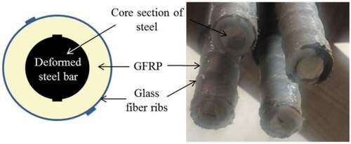
(SFCB) bars were manufactured using layers of longitudinal glass fibers, rolled around the steel bar, till the required diameter, as in . Raisin was poured to attach fibers to the steel to produce SGFB. Two high-grade steel (40/60) deformed bars of 16 cm diameter (10 mm steel and 6 mm glass fibers) were overlapped and spliced in the middle (moment) zone. Reinforced concrete beams were casted with concrete cross-sectional area of (25*40*420) cm as shown in . Stirrups were taken 5 mild steel bars (24/35) of diameter φ 8 per meter of beam length in addition to stirrup hangers of steel bars 2 φ 12-mm high-grade steel (40/60). Lap-splice length investigated was taken as in and stress distribution as in . G (C) has stirrups all along beam span and stuggered lap-splice as in . Clean and rounded siliceous sand and crushed rock as coarse aggregate along with ordinary Portland cement were used in such ratios to obtain a target concrete strength. The mix was designed to develop 28-day cube strength of 30 MPa. The wooden forms and the steel cubes were coated with oil before casting; the mixture is then casted and compacted using a vibrating electrical rode. The forms were removed 24 hours after casting, specimens were then cured by water for 28 days.
Figure 1. Manufacturing of SFCB.
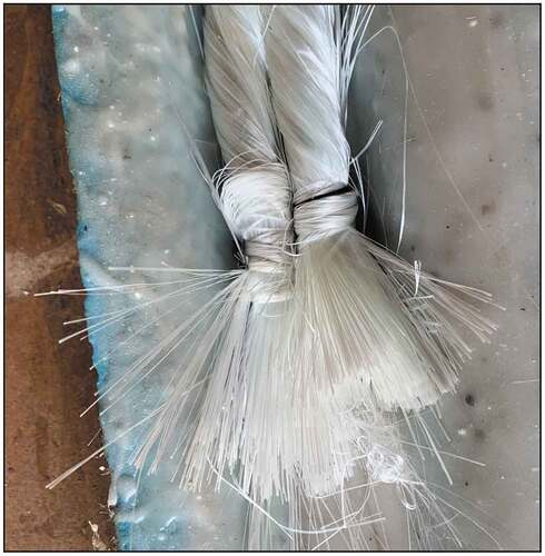
Figure 2. Manufacturing of SFCB longitudinal glass fibers rolled around steel bar pouring of resin.
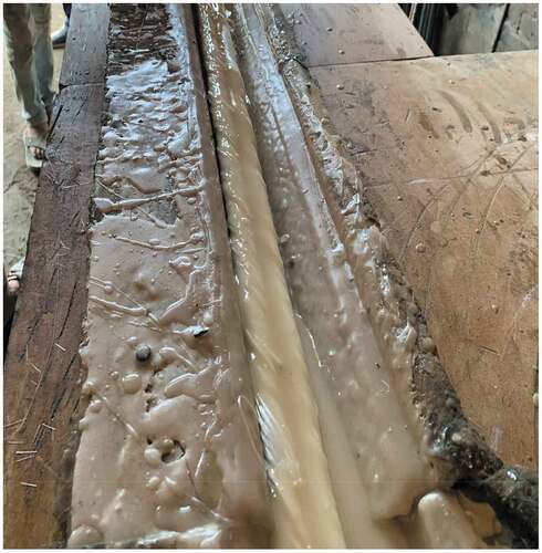
Figure 3. 10-mm steel core in addition to 6-mm glass fibers saturated in epoxy Resin.
Figures 4. a & b: Concrete Dimensions & Reinforcement detailing.
Figure 5. Developing length taken in this study for groups A, B & C.
Figure 6. Stresses in lap splice. Canadian Code CAN/CSA-S806-02, [Citation6]
![Figure 6. Stresses in lap splice. Canadian Code CAN/CSA-S806-02, [Citation6]](/cms/asset/4e625d41-635f-4901-8f60-87c093bb7e17/thbr_a_2155349_f0006_b.gif)
Figure 7. Stuggerred lap splice. Egyptian code of practice for reinforced concrete structures [Citation7]
![Figure 7. Stuggerred lap splice. Egyptian code of practice for reinforced concrete structures [Citation7]](/cms/asset/c667fa04-496d-47c4-879d-49aa382a0f8c/thbr_a_2155349_f0007_b.gif)
The experimental test program was executed in HBRC in Egypt. Test set up was computerized and contained the items as in . A four-point load was applied to create constant moment zone that is to say pure flexure strain. Beams were tested under increasing vertical load until failure. The load was applied by a vertical jack and the mid span deflection was measured by an attached horizontal LVDT.
Figure 8. Test set up.
Figure 9. Experimental equipments used in the set up.
Reinforcement detailing with and without stirrups at beam mid span (lap splice zone) are shown in .
Figure 10. Reinforcement detailing with stirrups at mid span (lap splice zone).
Figure 11. Reinforcement detailing without stirrups at mid span (lap splice zone).
Results, analysis and interpretation
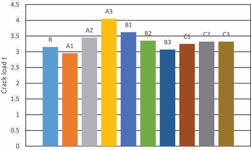
Data were recorded during the test through equal load increments as the test set up was computerized. Recorded data were as follows: specimen first crack load in tons, and the corresponding mid-span beam vertical deflection in mm. Failure modes and description of it were documented. Beam specimen (R) was taken as reference, percentage of change in crack loads along with corresponding deflections were calculated with respect to beam (R). Results are presented in .
Table 2. Lab results.
First crack load–mid-span deflection relationships within the elastic stage are presented in . G (A) that was characterized by stirrups and staggered lap-splice, G (B) that was characterized by absence of stirrups in the lap-splice zone and unstuggered lap-splice. (C) that was characterized by stirrups in the lap zone and stuggered lap splice.
Figure 12. First crack loads for tested beams.
Studying ten beam specimens with rectangle cross-section area of 25*40 cm and length of 420 cm exposed to pure flexure, with 2 hybrid (SFCB) bars of diameter φ 16 mm as main reinforcement spliced in tension zone. Taking beam (R) as a reference as it has no spliced steel and comparing important results, reached are as follows:
For Group (A) that was characterize by stirrups and staggered lap splice,
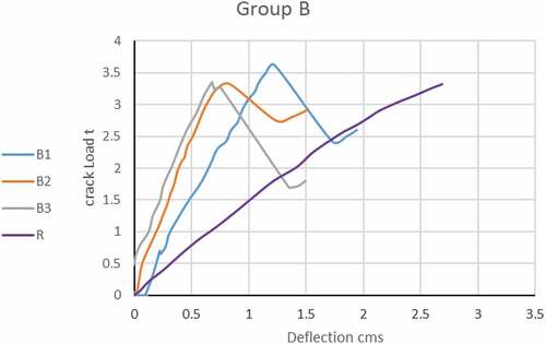
Figure 13. Crack Load vs Deflection relationships for Group (A) For Group (B) that was characterized by absence of stirrups in the lap-splice zone and unstaggered lap splice (.
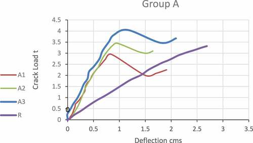
Figure 14. Crack load vs deflection relationships for group (B).
Taking the developing length equals 1.3*50 φ, decreased the first crack load by 6 % and decreased the corresponding mid-span deflection by 65% (beam A1)
Tacking the developing length = 1.3* 55 φ, increased the first crack load by 10% and decreased the corresponding mid span deflection by 61%. (beam A2).
Tacking the developing length 1.3* 60 φ, increased the first crack load by 29% and decreased the corresponding mid span deflection by 53% (beam A3).
Tacking the developing length = 1.3* 55 φ, increased the first crack load by 15% and decreased the corresponding mid span deflection by 50% (beam B1).
Tacking the developing length = 1.3* 60 φ, increased the first crack load by 5% and decreased the corresponding mid span deflection increased by 65% (beam B2).
Tacking the developing length = 1.3* 65 φ, increased the first crack load by 6% and decreased the corresponding mid span deflection by 73% (beam B3).
For Group (C) that was characterize by stirrups in the lap zone and stuggered lap splice, ;
Figure 15. Crack Load vs Deflection relationships for Group (C).
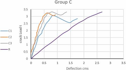
Tacking the developing length from 1.3*50 φ, decreased the first crack load by 3% and decreased the corresponding mid span deflection by 65%. (beam C1).
Tacking the developing length = 1.3* 55 φ, increased the first crack load by 3% and decreased the corresponding mid span deflection by 74% (beam C2).
Tacking the developing length = 1.3*60 φ, increased the first crack load by 5% and decreased the corresponding mid span deflection increased by 67% (beam C3).
Failure modes were due to bars slippage and loss of bond between concrete and reinforcement hybrid bars as shown in .
Figure 16. Cracks at failure of tested beams.
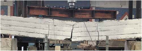
Figure 17. Failure mode of tested beams.

Conclusions
Generally, the spliced hybrid steel used as main reinforcement, changed the beams’ behavior to stiffer one, with the decrease of the elastic phase area, described by the change in slope of the load–deflection curves. This may be attributed to the loss of adhesion between concrete and hybrid steel at the ribs produced from surface friction, thereby reducing the beam bond strength. It is recommended to use minimum transverse reinforcement as stirrups within the splice zone to confine the cross section at failure and to control propagation of splitting cracks.
Disclosure statement
A conflict of interest may exist when an author or the author’s institution has a financial or other relationship with other people or organizations that may inappropriately influence the author’s work. A conflict can be actual or potential and full disclosure to the journal is the safest course. All submissions to the journal must include article title and disclosure of all relationships that could be viewed as presenting a potential conflict of interest and should be signed. The journal may use such information as a basis for editorial decisions and may publish such disclosures if they are believed to be important to readers in judging the manuscript. A decision may be made by the journal not to publish on the basis of the declared conflict. This declaration (with the heading ‘Conflict of interests’) should be also fulfilled on the cover page at the time of submission.
References
- Harris HG, Somboonsong W, Ko FK. New ductile hybrid FRP reinforcing bar for concrete Structures. J Compos Constr. 1998 February;2(1):28–37.
- Bestari Muin R. Muchammad sholeh,”assessment on tension bar lap splices of concrete reinforcement steel,” IOP Conference Series, Materials Science and Engineering,2018 IOP Conf. Ser.: Mater. Sci. Eng. 453 012068. https://www.researchgate.net/publication/329278831_Assessment_on_Tension_Bar_Lap_Splices_of_Concrete_Reinforcement_Steel
- Brahim Benmokrane R, Ebead U. Tensile lap splicing of fiber-reinforced polymer reinforcing bars in concrete. ACI Struct J. 2006;November–December. https://www.researchgate.net/publication/260368560_Tensile_Lap_Splicing_of_FRP_Reinforcing_Bars_in_Concrete
- Dong-Woo S, Ki-Tae P, Young-Jun Y, et al. Experimental investigation for tensile performance of GFRP-steel hybridized rebar. Adv Mater Sci Eng. 2016; Article ID. 9401427. DOI:10.1155/2016/9401427.
- David Darwin. Tension development length and lap splice design for reinforced concrete members, “ Published online 12 October 2005 in Wiley Inter-Science (www.interscience.wiley.com).
- Canadian Code CAN/CSA-S806-02, Design and construction of building components with fibre-reinforced polymers 2007
- Egyptian code of practice for reinforced concrete structures, HBRC,2021.