
ABSTRACT
Bridges are common and important constructions to overcome different obstacles in any transportation network. Variations in bridge types include variation in span length, statical system, construction material, construction methods and sustained loads. Choosing the suitable statical system is affected with several factors such as construction time, availability of materials, available budget, contractors’ background and one of the most important factors is the layout of the road network or obstacles outline beneath the bridge. Skew bridges result from inclined intersection between bridge axis and the below road or water stream. The famous problems that result from this inclination are distribution of loads among the main girders and variation in bearings` reactions. Stiffness of cross girders especially near the skew edge affects noticeably the distribution of loads in main girders. In this paper, analysis of medium span skew RC girder bridge deck will be proposed using different skew angles (α) measured from horizontal axis that are 20̊, 30̊, 40̊ and 50̊ and different cross girder patterns. Analysis will be performed using grillage model in FEM software package. Analysis includes different skew angles, different cross girder patterns and different distributed gravity load patterns. The observed outputs in the analysis are reactions at bearings and bending moment values in main girders. In this paper, effect of skew angles and different cross girders patterns on reactions at bearings will be introduced. The effect of these variables on main girders BM values will be discussed in extended paper work.
Introduction
The objective of this research is to find out the effect of skew angle and different cross girders` patterns on bridge bearings` reactions. The analysis was performed through grillage model analysis. Grillage model is a 2D model used in bridge decks and formed of frame (beam members only). Beam members are rigidly connected at nodes, and longitudinal members represent the stiffness of girders and top slabs including its own weight. Transverse members are zero weight beam members with the stiffness of the slab. Many researchers studied the effect of skew angles on bridge deck behavior and the distribution of loads and straining actions in the bridge deck. Razzaq M.K. et al [Citation1] had studied the effect of distribution factors in skewed composite steel I-Girder bridge due to dead loads, including effect of shoring and un-shored construction with different spans using CSiBridge FE program. They found that for large skew angles greater than 30̊ measured with the VL axis, a noticeable increase in shear and moment values was noticed at the outer main girders with increase in shear values at the obtuse angle. Variation is seen in BMD values distribution along the outer main girder; however, this variation was not noticed in shear. Rocha B.F. et al. [Citation2] had studied the effect of skew reinforcement applied in slab and plates in RC bridges. They concluded that for large skew angles, a higher steel reinforcement area at the mid panel is required to resist the noticeable increase of stresses in concrete at obtuse angle. The existence of girders did not change the location of increased stresses. Skew reinforcement meshes increase the amount of steel and concrete compressive stresses. Sindhu B.V. et al. [Citation3] also had studied analytically the effect of skew angle on RC slab bridges with and without edge beams. DL and LL were included in the analysis. They noticed a decrease in deflection with the increase of skew angles with a less decrease in LL. Peak value of support reactions was at the obtuse angle. Hassel H.L. et al. [Citation4] had conducted a parametric study using 3D FE models on the effect of cross frames layout on the distortion of skewed steel bridges. They found that cross frame layout and its stiffness had a great effect on distortion induced fatigue. Theoret P. et al. [Citation5] had studied how to determine the required straining action to design skew and straight slab bridges using grillage and FE models. They proved that grillage analysis was satisfactory to predict the amplitude and transverse distribution of longitudinal bending moments and shear forces. They concluded that non-orthogonal meshes are better than orthogonal one in load distribution, which did not agree with [Citation2]. Kar A. et al. [Citation6] had studied the effect of skew angles in skew bridges analytically by FEM and grillage model. The results showed a noticeable increase in reactions at obtuse angle with the increase in skew angle and decrease in bending moment’s values. Harba I.S [Citation7]. had studied the effect of skew angles on RC T-beams bridge decks and agreed in results with [Citation6]. Saber A., et al. [Citation8] & [Citation9]; had tested a full-scale model of continuous diaphragms in skew Prestressed girder bridges. Gupta T. et al. [Citation10] mentioned that skew angles have a great effect on support reactions especially in short and medium spans. They studied the behavior of RC T-beam skewed bridges using grillage analogy model and noticed that negative reactions was observed with the increase of skew angle and span length at acute angles. They also recommended grillage models due to its simplicity, easy in data preparing and less time consuming.
Model and analysis
Grillage model
Grillage model was adopted in the analysis due to its simplicity and acceptable accuracy and reduced analysis time. In the performed models, as the skew angle starts from 20̊, which is less than 30̊ as recommended by Hambly [Citation11], transverse elements will be in the perpendicular direction to the horizontal axis in all models. Neoprene bearings` modulus of elasticity was taken equal to 2.0 N/mm2 as per [Citation12].
Models` specifications
illustrates the analyzed models geometry and specifications, where examined two different main girders layouts and four different cross girders` patterns were adopted in the analysis. Skew bridge layout, bridge deck cross section and cross girders` patterns are as shown .
Figure 1. Skew bridge general layout and concrete dimensions.
Figure 2. Different X-girders patterns adopted in the analysis.
Table 1. Analyzed skew bridges configurations and layout.
Where: L= Span length of the bridge. W= Width of the bridge. S=spacing between main girders. Lc= Length of cantilever. α= skew angle measures from Hz axis. M1 is for Model 1 where spacing between main girders equal to 2.25 m and M2 is for Model 2 where the spacing between girders equal to 3.0 m. the numbers 20 to 90 are for the different skew angles measured from the Hz axis.
Load patterns
Analysis of FE (grillage models) was performed under gravity loads (DL) and live loads (LL). Dead loads include bridge own weight, own weight of pavement layers (SDL), weight of sidewalks and barriers. The adopted Live load (LL) pattern was taken LL pattern (1) as in according to The Egyptian code of loads and forces in structures and construction works 2008 [Citation14].
Figure 3. Live load pattern according to egyptian code for loads and forces in structures 2018 – load pattern no.1 [Citation13].
![Figure 3. Live load pattern according to egyptian code for loads and forces in structures 2018 – load pattern no.1 [Citation13].](/cms/asset/2894adef-da53-432c-abc3-d7b481a1c205/thbr_a_2215648_f0003_b.gif)
Verification model
Grillage model is a simple and fast modeling technique that can be used easily with satisfactory results. In order to verify grillage model accuracy relative to other FE programs, a comparison between analyses of skew slab Type Bridge using ANSYS was performed by Kishan G. et al. [Citation14]. They performed analysis of 6 m, 8 m and 10 m span bridges. The width of the bridge is equal to 5.0 m. Skew angles of the analyzed bridges were 0̊, 15̊, 30̊, 45̊ and 60̊. Thickness of the slab was 600 mm, 750 mm and 900 mm for the 6 m, 8 m, and 10 m bridge spans, respectively. Grillage model was performed to the 6 m and 10 m span bridges and skew angles 0̊, 30̊ and 45̊. Grillage model was divided with same number of divisions as in ANSYS. The same material properties were used in SAP [Citation15] model. The comparison was between BM values due to own weight in the two modeling techniques. In the following, represent BM values from ANSYS and SAP and the percentage of difference between them. As ANSYS BM values are measured about X and Y directions and grillage members were parallel to the skew edge, resolution of BM values was performed in the Y direction.
From the obtained results, the percentages of difference between ANSYS and SAP results were ranged from −11% to 12%. SAP results showed an acceptable percentage of difference between the two programs. Hence, Grillage model is considered a simple and fast modeling technique with a good accuracy.
Table 2. Comparison between ANSYS and Grillage model using SAP and the percentage of difference in BM values due to OW.
Results and discussions
Effect of skew angle and X-G pattern on bearings reactions
The analysis of skew bridges was performed using SAP 2000 16 software package. SAP2000 is a general purpose finite element program which performs the static or dynamic, linear or nonlinear analysis of structural systems. The analysis of main girders pattern 1 (M1–20 to M1–90) and different skew angles showed that the reaction due to DL at point (A) (obtuse angle) has increased with the decrease of skew angle as expected. However, the reaction also was affected with the X-girders pattern as shown in . illustrates that the percentage of increase in reaction at point (A) due to DL is proportional with the increase in bridge skew angle and the smallest increase percentage for moderate skew angle was with X-girders patterns 2 and 4 with percentage 14% and 12% for skew angle 50, and 35% and 31% for skew angle 40, respectively. However, for low skew angles, the least increase percentage was for X-girder pattern 3, with percentage of reaction increase of 54% and 83% for skew angles 20 and 30, respectively
Figure 4. Model (M1) bearing reactions at point (A) due to DL with different X-Girders patterns and skew angles.
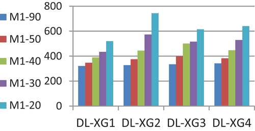
Table 3. Increase percentage in reaction at point (A) due to SDL relative to right bridge (model M1).
The reactions at support (A) due to SDL are illustrated in . indicates the percentage of increase in reactions relative to right bridge with different skew angles and cross girder patterns. The percentage of increase in reaction at point (A) due to SDL is proportional with the increase in bridge skew angle and the less increase percentage for moderate skew angle was with X-girders pattern 2 with percentage 3% for skew angle 50, for skew angle 40 the less percentage of increase relative to right bridge was 8% and 11% for X-girder patterns 1 and 2, respectively. However, for high skew angles, the minimum percentage of increase was for X-girder pattern 3, with percentage of reaction increase of 13% for X-G1 and similar for the other 3 patterns with average percentage of 34% in bridges with skew angles 30; for skew angle 20, the least percentage of increase is 23% in X-girder pattern 1 and almost the same for XG-3 and XG-4 with 49% and 48%, respectively.
Figure 5. Model (M1) bearing reactions at point (A) under SDL with different X-Girders patterns and skew angles.
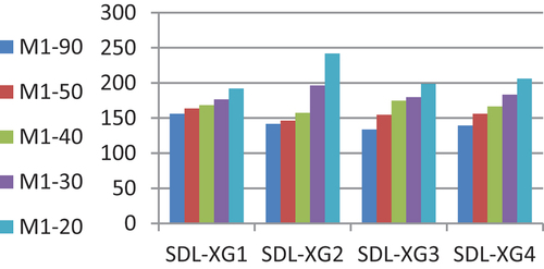
Table 4. Increase percentage in the reaction at point (A) due to LL relative to right bridge model (M1).
The reactions at support (A) due to LL are shown in . summarizes the percentage of increase in LL reactions relative to the right bridge with different skew angles and cross girder patterns. From , it can be noticed that for small skew angles (α = 20̊ and 30̊), the reaction due to LL has almost doubled relative to the reaction of right bridge due to cross girder patterns XG-2 and XG-4. XG-1 (no cross girders) and cross girder pattern XG-3 shared in better distribution of the reactions due to LL. In higher skew angles (α = 40̊ and 50̊), XG-1 resulted in the less increase percentage relative to right bridge. The effect of XG-2 and XG-4 on the reaction increase was almost the same.
Figure 6. Model (M1) bearing reactions at point (A) under LL with different X-Girders matterns and skew angles.
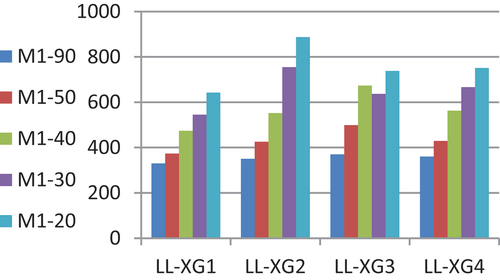
Table 5. Increase percentage in reaction at point (A) due to DL relative to right bridge (model M2).
The reactions at support (A) due to DL in Model (M2) with different skew angles and cross girders` patterns are shown in . illustrates the percentage of increase in reactions relative to right bridge with different skew angles and cross, and it can be noticed that the reduction of cantilever length and increase in spacing between main girders did not result in great difference in the reactions due to DL at point A in large skew angles (α = 50̊ and 40̊). However, small skew angles (α = 30̊ and 20̊) with all adopted cross girder patterns resulted in less increase in reactions at point A due to DL. The same cross girder patterns (XG-1 and XG-3) resulted in a better reactions distribution as in Model (M1).
Figure 7. Model (M2) bearing reactions at point (A) under DL with different X-Girders patterns and skew angles. .
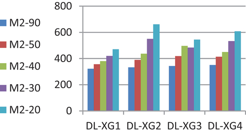
Table 6. Increase percentage in reaction at point (A) due to SDL relative to right bridge (model M2).
Reactions at support (A) due to SDL in Model (M2) are shown in . illustrates the percentage of increase in SDL reactions relative to right bridge with different skew angles and cross girder patterns. The percentage of increase in reaction at point (A) relative did not show a noticeable difference to that in Model (M1).
Figure 8. Model (M2) bearing reactions at point (A) under SDL with different X-Girders patterns and skew angles.
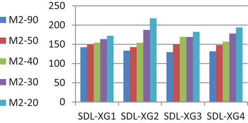
Table 7. Increase percentage in reaction at point (A) due to LL relative to right bridge (model-2).
Reactions at support (A) due to LL in Model (M2) are shown in . From , it can be noticed that for large skew angles, reaction due to LL at point A in large skew angle (α = 50̊ and 40̊) did not show great increase relative to right bridge or to Model (M1). However, small skew angles (α = 30̊ and 20̊) with all adopted cross girder patterns resulted in a big increase in reactions at point A due to LL relative to right bridge. However, the increase in reaction was less than Model (M1). Cross girder patterns XG-2 and XG-3 showed the largest increase in reaction at point A relative to all other patterns.
Figure 9. (a) model (2) bearing reactions at point (A) under LL with different X-Girders patterns and skew angles. (b) A comparison between bearing reactions at point (A) due to DL, SDL and LL with different X-Girders patterns and skew angles in model (M1).
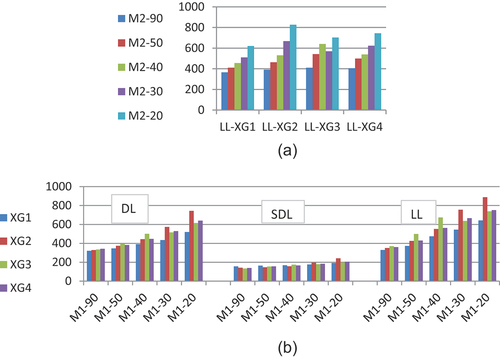
Figure 10. A comparison between bearing reactions at point (A) due to DL, SDL and LL with different X-Girders patterns and skew angles in model (M2)..
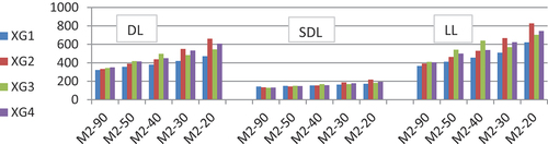
Table 8. Percentage of increase in reaction at point (A) due to LL relative to right bridge model (M2).
The percentage of variation in reactions due to DL, SDL and LL in Model (M2) compared to Model (M1) are summarized in . From the analysis results, the percentage of increase in reaction was 16.3% in LL reactions, with cross girder pattern 4 and skew angle 50̊. The percentage of reduction in reaction was −11.6% in the case of LL, with cross girder pattern 2 and skew angle 30̊
Table 9. Percentage of variation in reaction at point (A) due to DL, SDL and LL in model (M2) compared to model (M2).
Conclusions
In this paper, analysis of 40 bridges with different skew angles and different cross girder patterns was performed through grillage model and live load patterns according to Egyptian Code of Practice. The analysis aimed at finding the effect of skew angle on bearing reactions due to DL, SDL and LL. From the previous analysis, the following conclusions were drawn:
Reaction at the bearing (A) in Model-1 in obtuse angle has increased with the decrease of skew angle due to DL, SDL and LL. For DL, the increase in reaction ranged between 8% to 12% in skew angle 50̊ with the different cross girder patterns. The maximum increase was 31%, 55% and 87% for skew angles 40̊, 30̊ and 20̊, respectively.
For SDL, the maximum increase in reaction ranged from 12% up to 48% with skew angles 50̊, 40̊, 30̊ and 20̊, respectively, and slight change with the different cross girder patterns.
The maximum increase in LL reaction at point (A) relative to right bridge was observed in XG-3 for moderate skew angles and in XG-2 in small skew angles 20̊ and 30̊.
In small skew angles, XG-2 pattern (one cross girder in the middle of the deck) resulted in increase in DL and LL reactions at point (A), that means less uniform distribution of the loads.
Reactions at Point (B) acute angle did not show a noticeable effect with the change of cross girder patterns with maximum reduction in DL reactions 4% and increase in LL reactions 17%.
Grillage model was a simple and fast analysis model with acceptable results which helps to carry out large number of models with acceptable accuracy.
Disclosure statement
No potential conflict of interest was reported by the author.
References
- Razzaq MK, Sennah K, Gharib F. Moment and shear distribution factors for the design of simply supported skewed composite steel I-Girder Bridges due to dead loading. J Bridge Eng. July5 2020;25:04020060.
- Rocha BF, Schulz M. Skew Decks in reinforced concrete bridges. IBRACON Mater Struct. 2017 February;10(1):192–219.
- Sindhu BV, Ashwin KN, Dattatreya JK, et al. “Effect of skew angle on static behavior of reinforced concrete slab bridge decks”, Internationa Journal of Research in Engineering and Technology, “IJRET”, IC-RICE Conference Issue—November, 2013.
- Hassel HL, Bennett CR, Matamoros AM, et al., “Parametric analysis of cross- frame layout on distortion-induced fatigue in skewed steel bridges”, Journal of Bridge Engineering, Volume (18) No.7, July 2013, P 617–623.
- Theoret P, Massicotte B, Conciatori D. Analysis and design of straight and skewed slab bridges. J Bridge Eng. 2012 March/April;17(2):289–301.
- Kar A, Khatri V, Maiti PR, et al. Study on effect of skew angle in skew bridges. Int J Eng Res Dev. 2012 August;2(12):13–18.
- Harba IS. Effect of skew angle on behavior of simply supported RC T-Beam bridge. J Eng Appl Sci. 2011;6(8):1–14.
- Saber A, Alaywan W. Full-scale test of continuity diaphragms in skewed concrete bridge girders. J Bridge Eng. 2011 February;16(1):21–28.
- Saber A, Toups J, Guice L, et al. Continuity diaphragm for skewed continuous span precast prestressed concrete girder bridges. LTRC Project No. 01-1ST. June 2001–June 2003. State Project No. 736-99-0914. Louisiana: Louisiana Department of Transportation and Development, Louisiana Transportation Research Center. October2004. FHWA/LA 04/383.
- Gupta T, Misra A. Researchgate. Effect on support reactions of T-Beam skew bridge decks. ARPN J Eng. 2007 February;2:No.1.
- Hambly EC. “Bridge Deck behavior”. 2nd ed. London: E&FN Spon Routledge; 1991.
- Ronald AC, Allen DT, Ansley MH. Engineering and Industrial Experiment Station. Stiffness evaluation of Neoprene bearing pads under long term loads. In UF project no. 00051121. Gainesville, Florida: Department of Civil & Coastal Engineering University of Florida; 2009 March.
- Egyptian code of practice for loads and forces in buildings and structures, ECP201, 2008.
- Kishan G, Shashiktant S. SkEW BRIDGE ANALysis using ANSYS. Int J Eng Res Technol. 2020, June;9(6): 870–875.
- SAP2000. Advance 16.0.0, structural analysis program. V16 ed. Computer and Structures Inc. CSI; 2013.