
ABSTRACT
Aeration is a process of diffusing oxygen into water in order to stimulate the aerobic bacteria for starting wastewater aerobic treatment process. Zero energy aeration systems that do not require electric or mechanical power are known as passive aerators. A new technology for passive aerators using inverted bell siphon principle is innovated, which requires a lot less volume for its installation compared to other passive aeration systems as cascade, spray and perforated tray aerators. A laboratory experimental program investigated the inverted bell siphon system using deoxygenated water with almost zero dissolved oxygen concentration like anaerobic treatment effluent. The system is used to build water pressure through a distribution system used for scattering water in air to diffuse oxygen into it. Holed arm pipe with different hole diameters and numbers, showerhead, fire sprinkler and modified fire sprinkler were tested as distributors to reach the optimum type which verify good oxygen diffusion in water and ensure least possibility of clogging of distributors. Dissolved oxygen concentration was measured for each distributor water effluent. The experiments showed that the modified fire sprinkler achieved higher oxygen diffusion in water and best distribution, in addition to its geometry that prevents the distribution system from clogging.
Introduction
Aeration is the process of allowing water to dissolve gases (especially oxygen) from air. Oxygen in the air serves as an oxidizing agent and helps to chemically transform or eliminate many noxious and toxic contaminants that might be present in wastewater [Citation1]. The process takes place by bringing water and air into close contact in order to remove dissolved gases, such as carbon dioxide, and to oxidize dissolved metals such as iron. It can also be used to remove volatile organic chemicals in the water. Aeration is often the first major process at the treatment plant. During aeration, constituents are removed or modified before they can interfere with the treatment processes [Citation2]. An anaerobic treatment method has a limitation in that it cannot, by itself, produce effluent that is acceptable for release into receiving waterbodies by the limits of law 48/year 1982 concerning the protection of the Nile River and waterways from pollution [Citation3]. Because of this, an aerobic treatment unit is used as a post-treatment ought to be added after the anaerobic [Citation4]. In order to promote this transition, aerobic bacteria must be stimulated by oxygen in order to start an aerobic treatment process [Citation5]. The aerobic bacteria require dissolved oxygen (DO) concentration in water of at least 3.5 mg/l to start its action in wastewater aerobic treatment [Citation6].
Aerators are generally divided into two main categories: mechanical and passive aerators [Citation7]. Mechanical aerators use power to pump air to water or vice versa. They are commonly used for their small installation space and high efficiency as spray aerators, diffusers, turbine aerators and venture microbubble aerators [Citation8–10]. These types of aerators consume electricity and their mechanical parts require frequent maintenance and relatively high operating cost. As a result, a more inexpensive, practical and sustainable choice for aeration is required. These requirements can be fulfilled by employing passive aeration methods that do not use any electrical power, such as drop, cone, tray and cascade aerators [Citation7,Citation11]. As these aerators need an influent water head to raise water at the top of the aerator construction, also even a large area footprint or/and height for their installation [Citation12], the objective of this research is to study the use of bell siphon aerators to increase the DO concentration in deoxygenated wastewater as a more practical option for tight spaces and low-influent pressure head.
Materials and methods
System description
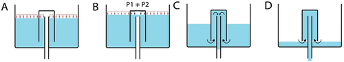
The system consists of a reservoir for collecting deoxygenated water, a bell shaped as an inverted cup with vents in its bottom to connect the reservoir with the inverted bell so the water can enter the inverted bell from the reservoir and also a riser circulated cross section tube to get water out of the bell to distribution system following the siphon. The riser tube should be distanced away from the top of the inverted bell to make a room for generating negative pressure inside the bell.
As water fills the reservoir, the surface of water in and out the bell is equally exposed to atmospheric pressure as shown in . Once water rises over the riser tube surface forming a seal closing the bell’s connection to the atmospheric pressure and making difference in pressure between the inner part of the bell and the outer atmospheric pressure of the reservoir as shown in , as water falls through the riser tube, it generates a vacuum over the riser tube inside the bell draining more water from the reservoir, as shown in , eventually water levels drop below the bell bottom where air enters and the pressure is equalized stopping the siphon action, as shown in .
Figure 1. Steps of bell siphon working process.
The experiment was performed using synthetic deoxygenated water, using nitrogen gas tube to ensure water with almost zero DO to simulate the raw wastewater or effluent from the anaerobic reactor and measuring the DO concentration after the experiment.
Experimental steps and runs
The experimental work consists of four steps:
Optimizing bell siphon dimensions and operation
Deoxygenation of water entering bell siphon system
Testing several types of effluent distributors
DO concentration measurement
Optimization of bell siphon dimensions and operation
This step aims to test the theory of bell siphon effect on increasing the water pressure effluent as a free discharge out of the riser tube to atmosphere, also optimizing the relative dimensions between the reservoir dimensions, the inverted bell cup dimensions and the riser tube size and height inside the bell cup. The reservoir used in all the testing trials was 9 L in volume with 24 cm length, 15 cm width and 25 cm height with net effective height of 22 cm.
Dimensions of the inverted bell cup were tested on different sizes. Bottles measuring 0.66, 3.7 and 1.2 L were used in the test to choose the optimum volume and dimensions of the inverted bell. It was observed that 1.2 L was the best for running the siphon process smoothly and for feasibly low return of water from the bell when the system breaks at last. This bell was tested several times to ensure progress facility and ease in pumping water out of the system with appropriate pressure.
The riser tube used was a 0.5-inch polypropylene material. and its height effect was tested inside the bell to reach the optimum gap distance between the riser top surface and the bell’s top. The value of this gap is to make the negative pressure inside the bell which generates the water chain to get water from the reservoir in and out the of the bell through the riser tube. The gap height was observed to be at least twice the diameter of the riser tube to ease the process of the siphon. The gap was fixed to be 3 cm height for all runs. For more efficient water block over the riser surface, a reducer (0.5 inch to ¾ inch) fitting was inserted on the top of the riser to collect more water over its circumference for increasing odds of generating water block action over the riser tube surface.
Deoxygenation of water entering bell siphon system
As known, water deoxygenation is carried out by exposure to low-O2-concentration gas and/or vacuum conditions to draw O2 and other residual free gasses out of the water, causing the dissolved O2 to ‘outgas’ into the lower-concentration gas or vacuum. The setup was made by using nitrogen gas to deoxygenate water as its low concentration and capability of expulsing and taking place of oxygen out of liquids. This step aimed to produce almost zero DO water as a simulation to anaerobic treatment effluent in wastewater treatment.
Testing several types of effluent distribution
This stage aimed to test the DO concentration in water effluent the distribution system using several distributors, seeking an optimum distributor that serves the best oxygen diffusion in water (higher than 3.5 mg/l). This step was taken on six runs that will be discussed further. The transition from one run to the next was based on the results of the current run and the defects that appeared during this run and comparing results of each to reach the optimum distribution.
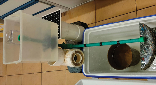
The first run was using 50-cm-long arm pipe with three holes distributed along the arm length with 16.5 cm spacing, as shown in . The run was tested two times: the first with holes with diameter of 10 mm and another one with 7 mm diameters.
Figure 2. Arm pipe distributor connected to the bell siphon.
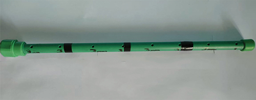
The second run was using similar arm pipes as in the first run, but the number of holes and their diameters was changed: three holes with 5 mm and eight holes with 3 mm diameters as shown in with a total area of 58.9 and 56.55 mm2, respectively (almost the same area). Holes were distributed along the arm length with 16.5 cm spacing for the 5 mm holes and 6.5 cm for the 3 mm holes, and the arm pipes were fixed at a distance of 30 cm over a collecting tank where DO concentration is measured.
Figure 3. Arm pipe with eight holes with 3 mm diameter each.
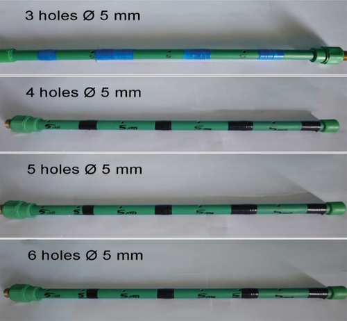
The third run was using similar arm pipes with holes having a diameter of 5 mm each with different numbers of holes to obtain its effect on effluent water pressure and DO diffusion into water. Arm pipes with three, four, five and six holes having a diameter of 5 mm each as shown in were tested with total surface areas of 58.9, 78.4, 98 and 118 mm2, respectively.
Figure 4. Arm pipe with different numbers of 5 mm holes tested.
The fourth run was using a showerhead having 20 holes with a diameter of 2 mm each, built on a 35-cm-long arm pipe terminal with a total hole area of 62.8 mm2. The showerhead and the arm to it are shown in .
Figure 5. Showerhead built on the arm pipe connected to the siphon.
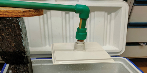
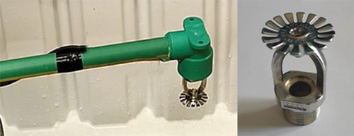
The fifth run was tested on an indoor fire sprinkler. It has an outlet whose diameter is half an inch, and as a rounded splashing plate, that water falls on and get splashed and disturbed in air, which increases the exposed surface area of water to air in order to facilitate oxygen diffusion in water. The fire sprinkler was connected to the bell siphon on the terminal of an arm pipe with 30 cm length as shown in .
Figure 6. Fire sprinkler built on the arm pipe connected to the siphon.
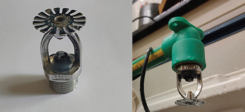
The sixth run tested the same indoor fire sprinkler used in the fifth run with the same arm pipe connection but with a modification to the outlet. The outlet diameter was reduced to be 5 mm rather than half an inch to increase concentration of water to center of the splashing plate and increase pressure inside the outlet section as shown in .
Figure 7. Modified fire sprinkler.
DO concentration measurement
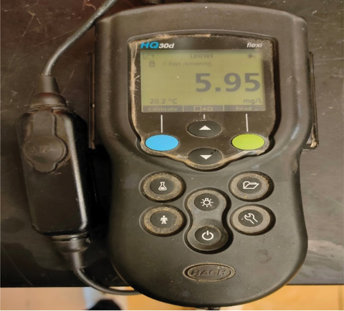
DO concentration was measured using HACH DO meter, as shown in , for water entering the bell siphon system (deoxygenated water) and for effluent water.
Figure 8. HACH DO meter.
Results and discussion
Deoxygenated water preparation
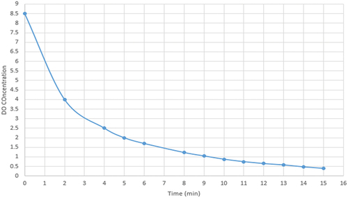
Deoxygenation of water was measured with respect to time to reach the lowest DO concentration. The process aimed to decrease DO concentration for 50 L of water from 8.5 mg/L which is the concentration of a saturated fresh water to 0.4 mg/L (simulated to anaerobic wastewater treatment effluent). This process required 15 min, as shown in .
Figure 9. DO concentration in deoxygenation process.
DO results for different types of ’ effluent water
The observed effluent water pressure of the first run did not satisfy the expected water jet to be capable of reaching the required goal of water oxygenation; therefore, DO concentration was not measured for this run.
In the second run, the number of holes of different diameters and total same area are compared. Different numbers of holes were used to try to fix the total cross-section area of the holes to test one parameter which is the water jet height and oxygen diffusion into it. The experiment was carried out two times for each arm pipe and DO concentration was measured five times in each test. The results of this run are illustrated in and .
Figure 10. DO concentration results for the 5-mm and 3-mm hole sizes.
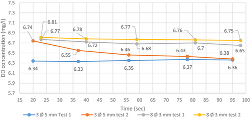
Table 1. DO concentration results for the 5-mm and 3-mm holes sizes in the second run.
From the results, it was observed that DO concentrations were high (higher than the required DO value for aerobic bacteria stimulation [3.5 mg/L]). Also, it is not quite affected by diameter variation for the same holes areas, since all readings were nearly close. So, it is better to use holes with 5 mm diameter (the larger diameter) to avoid clogging of the holes when it is used with wastewater.
In the third run, different numbers of holes with same diameter (5 mm) are compared. The reason behind varying numbers of holes with the same cross-section area of each holes is to test the effect of holes number on the water jet height and oxygen diffusion into it in parallel to system draining time, and the effluent water jet observed was quite promising to be measured. DO was measured eight times for each arm pipe test. The results of this run are illustrated in and ).
Figure 11. Effect of holes number on the average DO concentration.
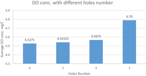
Figure 12. Relation between draining flow results and different numbers of holes tested.
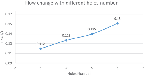
Table 2. DO concentration results for the 5 mm size with different numbers of holes in the third run.
From the results, it was observed that DO concentrations are affected by changing vents total cross-sectional area as water flow increases with increasing number of holes, while water pressure was distributed over larger number of holes, resulting in a shorter water jet which gives a smaller contact time of water jet with surrounding atmosphere to diffuse oxygen inside water, concluding that larger vents cross section is inversely proportional to DO diffusion.
In the fourth run, a showerhead was experimented, and the purpose of this experiment is to test a distributor type that can distribute water uniformly over the targeted area. The experiment was carried out two times and DO was measured ten times in each test. The results of this run are shown in and .
Figure 13. DO concentration relation for two trials using showerhead with time.
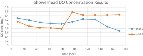
Table 3. Results for the showerhead run.
From the results, it was realized that this distributor type had a well effluent DO concentration and better distribution of the effluent over targeted area than the arm pipe distributor, while some disadvantages were observed while running:
Siphon process did not start working because of the narrow vents of the showerhead that prevented escaping of air out of the bell while filling the reservoir.
Frequent crashing of siphon during water exit from the system.
The 2 mm diameter of the vents is highly exposed for clogging with suspended solids when used for wastewater.
In the fifth run, an indoor fire sprinkler was experimented, and the purpose of this experiment is to test a distributor type that can distribute water uniformly over the targeted area and overcome the defects of the showerhead illustrated in the fourth run. The experiment was carried out and DO was measured eight times in this test. The run results are shown in and .
Figure 14. DO concentration results of fire sprinkler with time.
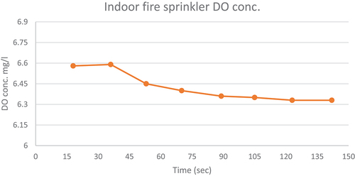
Table 4. Results for the indoor fire sprinkler run.
In the sixth run, a modified indoor fire sprinkler was experimented, and the purpose of this experiment is to test the modification between the normal indoor sprinkler and the modified one on the pressure of the effluent water jet over the splashing plate, also, the modification effect on the oxygen diffusion by dependency. The experiment was carried out two times and DO was measured eight times in each test. The results are shown in and .
Figure 15. DO concentration results of modified fire sprinkler with time.
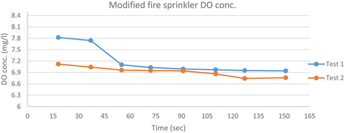
Table 5. Results for the modified indoor fire sprinkler run.
All six runs taken in this experiment aimed to reach the optimum type of water distributor that saves both high water aeration and to verify non-clogging of the system since semi-treated wastewater will path through it running from anaerobic treatment phase to aerobic treatment phase. The decision made for choosing a type of distributors between all runs made by comparing the average DO results taken by each run is shown in and .
Figure 16. Comparing average DO readings for tested distributors.
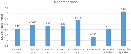
Table 6. Results for average DO readings for all tested distributors.
Conclusion
From the experiment results, the following conclusions may be noted:
All the distributors tested, except the showerhead, are good in water distribution and serve an acceptable oxygen diffusion into water.
Holes diameter in arm pipe is inversely proportional to effluent water jet.
Number of holes in arm pipe affects inversely with effluent water jet and affects directly with effluent flow.
The use of showerhead as a distributor is not advised due to its frequent crashing of siphon during the process of water exiting from the system and its small outlet vents that are more exposed to clogging.
The modified fire sprinkler achieved the highest DO concentration diffused to water and, therefore, its use is advised. Also, it offered a well effluent distribution over the targeted area without the fear of being clogged when being used in wastewater aeration process.
Passive aeration is an innovative technology for wastewater treatment, and the method proposed by the research can be effective in increasing the concentration of DO in wastewater. The effectiveness of this method varies depending on a set of factors, including system design, rate of water flows and the type and concentration of dyes in wastewater.
Therefore, we recommend the following: There is no objection to the application of this technology in the ventilation process in experimental models of wastewater treatment to confirm the results. Research and edit the best practical results.
Disclosure statement
No potential conflict of interest was reported by the authors.
Additional information
Funding
References
- Menon R, “Why cascade aeration used in treatment plant.” https://www.quora.com/Why-is-cascade-aerator-used-in-a-water-treatment-plant
- Twort R, C A, J B. Specialized and advanced water treatment processes water supply Aeration. 2000.
- “Law 48/year 1982 concerning the protection of the nile river and waterways from pollution”.
- Kassab G, Halalsheh M, Klapwijk A, et al. Sequential anaerobic–aerobic treatment for domestic wastewater – a review. Biores Technol. 2010;101(10):3299–3310.
- Sabry TI. An integrated anaerobic-aerobic system for sewage treatment. 2020.
- Bian X, Wu Y, Li J, et al. Effect of dissolved oxygen on high C/N wastewater treatment in moving bed biofilm reactors based on heterotrophic nitrification and aerobic denitrification: nitrogen removal performance and potential mechanisms. Biores Technol. 2022;365:128147.
- El-Zahaby AM, El-Gendy AS. Passive aeration of wastewater treated by an anaerobic process - a design approach. 2016.
- BOYD CB, TUCKBR CS. Pond aqua culture water quality manegment. 1951.
- “Fine pore aeration systems EPA-625-1-89-023.Pdf”.
- De Oro Ochoa E, Carmona García M, Durango Padilla N, et al. Design and experimental evaluation of a venturi and venturi-vortex microbubble aeration system. Heliyon. 2022;8(10):e10824.
- A MN, Mohd Remy Rozainy WC, Rhahimi Jamil AizatAbas MAZ. Lattice-Boltzmann study of cascade aerator system. 2016.
- Zou J, Guo X, Han Y, et al. Study of a novel vertical flow constructed wetland system with drop aeration for rural wastewater treatment. Water Air Soil Pollut. 2012;223(2):889–900.