Abstract
This article is concerned with the detection of environmental ageing in adhesively bonded structures used in the aircraft industry. Using a transmission line approach a forward model for the reflection coefficients is constructed and is shown to have an analytic solution in the case of constant permeability and permittivity. The inverse problem is analysed to determine necessary conditions for a unique recovery. The main thrust of this article then involves modelling the connector and then experimental rigs are built for the case of the air-filled line to enable the connector parameters to be identified and the inverse solver to be tested. Some results are also displayed for the dielectric-filled line.
1. Introduction
The imaging of the conductivity and permittivity of a heterogeneous material by electromagnetic field measurements is an inverse problem that is often called “impedance tomography”. It has applications in many areas such as non-destructive testing (NDT), radar and oil-pocket location. An NDT problem associated with the aircraft industry is that of testing adhesively bonded joints in airframe structures Citation1. The bonds can become weakened by bird strikes, lightning or thermal stress, eventually leading to water ingress, oxidation and bond failure. Recovery of the spatially dependent dielectric properties can provide an indication of water ingress and consequently some insight into the strength of the bond.
Among the many techniques that exist for NDT of adhesively bonded structures in aircraft are ultrasonic, radiation, thermal and eddy current techniques Citation2. However, there is no single technique that can classify completely the “state of the bond”. Computer controlled high-frequency vector network analysers (VNAs) have been employed to gain information on dielectric values of bonded structures Citation3,Citation4. The VNA sends an electromagnetic wave down the structure and receives a reflected response, effectively treating the structure like a waveguide. The reflection coefficient measured is given as a ratio of the reflected wave to that of the wave emitted by the VNA and is obtained through a range of frequencies.
This article is concerned with the development of a multilayered model of a dielectric-filled transmission line and the recovery of the electrical and spatial parameters characterising that line. A forward model for the determination of the reflection coefficients has been developed in Citation5. In this article, we revisit this model and focus on the simpler test case of an air-filled line. This leads to a clearer understanding of the different roles played by the connector and line parameters in the cost function. We also derive a necessary condition for the uniqueness of the inverse problem detailed in Citation5. Finally, we derive an exact solution to the Riccatti difference equation which arose in the analysis in Citation5.
2. The forward problem: determination of the reflection coefficient in a multilayered medium
Following Norgren and He Citation6, we shall employ transmission line theory to model the adhesively bonded structures. However, in contrast to their work, we shall be interested in spatially varying bonds and consequently shall consider a multilayered approach Citation5. In addition the differential equation relating the reflection coefficient to the physical parameters of the structure will be solved analytically. This has the advantage that not only can the uniqueness of the recovered solution be analysed, but also that an analytic expression for the Jacobian can be obtained leading to substantial improvements in the computational efficiency of the optimisation algorithm.
Since there are two aluminium plates bounding a dielectric slab we shall, as we have stated, exploit transmission line theory. However, although the aluminium plates bounding the dielectric slab are highly conducting they are nevertheless not infinitely conducting. This will result in fringe field effects that will contribute to the attenuation of any electromagnetic wave propagating between the two aluminium conductors; as we shall see later this will have a small effect on the inverse problem. To facilitate our discussion on the uniqueness problem we must necessarily repeat some of the key equations from Citation5.
Transmission line theory exploits a particular set of travelling wave solutions of Maxwell's equations. From these the telegraph equation may be derived in matrix form Citation6
(1)
where ε is the permittivity, μ is the permeability, ω is the angular frequency, W is the plate width, d is the plate separation (for the present assumed constant), g = W/d, and V(z) and I(z) are the voltage between, and the current through the plates ().
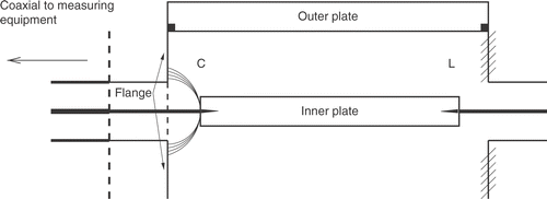
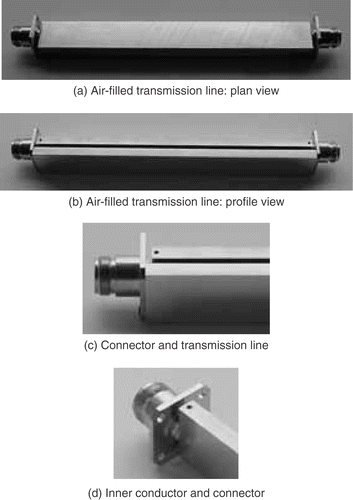
Figure 1. The air-filled transmission line. Plate separation d=2.7±0.05, mm, width W=23.04, ± 0.02,mm, length L=198 ±2,mm (inner = 196 mm, outer = 200 mm), ε = ε0, ρ = 0.56, μ Ωm and Z0 = 50 ,Ω.
The reflection coefficient r is measured at either end of the aluminium structure (z = 0 and z = L where L denotes the length of the structure) providing two reflection coefficients over a range of frequencies. Loss through polarisation and the skin effect is also taken into account Citation5. In a multilayered approach in order to obtain the reflection coefficient , in addition to the line parameters
for each layer, the boundary condition at z = L is also required. The parameter ℓi is the length of ith layer such that
. The governing differential equation in this multilayered context is Citation5
(2)
subject to
where
,
,
and
Citation7–9. Now equation (2) is a Riccati differential equation and as such admits the recurrence relation
(3)
where
,
,
,
and
Thus given a boundary condition at z = L (i.e. rm+1) and the parameters xi, the recurrence relation (3) may be used to obtain the solution for r0.
Reversing the indexing in (3), so that m increases from 0 to M, gives a Ricatti difference equation
(4)
For the homogeneous case, that is constant permeability and permittivity, it may be solved exactly to obtain (see appendix)
(5)
Comparing this with (3) it can be seen that the reflection coefficient at layer m consists of raising the parameter E to the power m. Thus this analytic solution correctly predicts that the reflection coefficient of m layers is the same as a layer of length mℓ. However for the inhomogeneous case it would appear that no such analytic solution exists in general.
3. Necessary conditions for a unique recovery
In this section, we shall address the question of uniqueness of the line parameters. Clearly a necessary condition for the recovery of a unique set of line parameters is that Ai and Bi must be known uniquely. Since the width of the structure was experimentally determined, the parameter W is considered to be known. Furthermore, since the measuring equipment has a characteristic impedance of 50Ω for any selected frequency ω, the characteristic impedance Z0 and the frequency are also considered to be known. Assuming then that Ai and Bi are known uniquely, then
(6)
Therefore knowledge of Ai and Bi yields the ratio ai / bi. Solving for ai and bi gives
(7)
Thus to resolve ai and bi the value of must be known. Note however that since
then
(8)
Thus ℓi must be uniquely known to give uniquely. From the expressions for ai and bi we also have
(9)
and
(10)
Thus we see that the ratio of the permittivity and the plate separation and that of the product of permeability and plate separation
may be calculated. Hence
(11)
Resolving this into real and imaginary parts gives
(12)
and
(13)
Addition of these two equations resolves di (provided W and μ0 are known). Furthermore (13) gives
(14)
The permittivity εi is then determined from (9):
(15)
In section 2 we have
(16)
where
and
are the infinite and static permittivities, respectively.
Multiplying the numerator and the denominator by the complex conjugate of and taking the principal root of j we get
(17)
where
and
In polar form this may be written as
(18)
where
and
Splitting into real and imaginary parts results in
(19)
where
and
Finally taking real and imaginary parts of (19) yields
and
which then gives
where α,β and τ are assumed to be known. Therefore given the parameters
and ω, the line parameters
and di can be uniquely reconstructed. Note the implication of these results: we cannot simultaneously reconstruct the parameters
(in the simpler case of the air-filled line). This is because ρ W and d are related by the two equations (12) and (13) and consequently it is only possible to uniquely recover two of these parameters. The air-filled line is important, not only in its own right as a special case of the resin-filled line, but also a vehicle for modelling the connector as we shall see in the next section.
4. Modelling the connector
Before resolving the spatial variation of the permittivity, resistivity and plate separation a model of the experimental connector is required Citation5. An air-filled transmission line was constructed from tool plate aluminium 6 mm thick with a flatness of 50μm in 1 m and a roughness of 0.6,μm (). The two plates were held in place by type N female connectors and the separation along the length was 2.7 ± 0.05,mm. The inner plate was 196 mm long and the outer 200 mm. The difference in length of the inner and outer conductor is clearly seen in . The width of both plates was 23.04± 0.02 mm. The resistivity of the aluminium was measured as 0.56 ± 0.03μΩm. Reflection coefficients were obtained using an Agilent 8753Es network analyser calibrated with a set of type N standards. Measurements were made at 801 linearly spaced points between 7.5 MHz and 6 GHz.
The VNA was connected to the air-filled line by a coaxial cable which terminated in a type N male connector. The air-filled plates were constructed with two type N female connectors that controlled the plate separation and avoided the need to use insulating spacers to fix the plate separation. There was no attempt to match the impedance between the VNA and the line since the permittivity could vary greatly from one test piece to another and was required over a large frequency range.
The connector was modelled as a length of lossless 50Ω line to account for the distance between the VNA calibration plane and the point of contact with the line. Also included in the model was an excess capacitance and inductance at the point of contact: the capacitance characterises the additional electric field between the inner plate and the connector flange () while the inductance represents the additional current path from the outer coaxial conductor to the outer plate.
Initial measurements suggested that the electric length of the connector was about 15 mm. The excess capacitance Cc was estimated to be about 1 pF and the excess inductance Lc to be about 0.1,nH. The contact resistance was estimated to be less than 0.01,Ω and was neglected. The contact resistance estimate is based on the manufacturer's specification Citation11, the inductance estimate is from a simple calculation of the inductance of the additional path taken by current from the outer of the type N connector and the capacitance estimate is again a simple calculation based on the geometry of the connector. Similarly, the conductance between the inner and outer conductors of the connector was typically about 10-12S and was also neglected. The impedance of the line at the connector--structure interface was calculated from
(20)
This impedance was then used to calculate the total impedance of the line and the connector–structure interface.
(21)
The original model was now modified to include the connector term and the recovery parameters were augmented by Cc and Lc. The connector was modelled in two stages: a connection between the connector and the structure (connector–structure interface) and a connection between the connector and the coaxial cable (coaxial--connector interface). The reflection coefficient from the line just before the connector–structure interface is r1 while the reflection coefficient just after the connector–structure interface will be denoted by r0, that is and
. However any wave travelling from the measuring equipment must travel some effective distance Δz, say, beyond the coaxial--connector interface (calibration plane) to actually reach this interface. This length (Δz) was treated as the length of an ideal coaxial line of 50Ω characteristic impedance and as such produces a phase shift between the measured reflection coefficient rcal and the modelled reflection coefficient r0. Hence, the reflection coefficient was given by
where k is the wave number. Thus the reflection coefficient as observed by the measuring equipment has been shifted in phase by 2kΔz.
The coaxial connector was partly constructed with an air dielectric and partly with a polytetrafluoroethylene (ptfe) dielectric so the length Δz was in fact an effective length equal to that which a connector with an air dielectric would have had. Measurements suggested that this equivalent (electrical) length was 15 mm. The reflection coefficients from the model for the air-filled line were now produced taking into account the connector. Qualitatively, these results compared favourably with the experimental results (for more details see Citation10).
A non-linear least squares method was now employed to solve for the unknown parameters , (see section 5)]. The objective function to be minimised, with respect to s, was
(22)
for supplied reflection data rd (ωk) from the boundary conditions. Constraints on the parameters were specified by the experimental error bounds ().
Table 1. Constraint on optimisation variables.
Larger bounds were set for the length and resistivity to account for the unknown effects of the two differing conductor lengths and of the conductivity of the conductor surface layer. The constraints were also used as an interval in which to generate 20 uniformly distributed random initial conditions for each parameter. This set of initial conditions was augmented by a set which was predicted from physical measurement. This spread of initial conditions provided some insight into the form of the objective function. In particular we were interested in whether certain subsets would converge to a unique minimum, or if they converged to a local minimum and if so were they closely clustered, well separated or periodic in some sense (for further details see Citation10).
For the air-filled structure the experimental data was initially used by the inverse solver to reconstruct the line parameters for the length L, width W, plate separation d and resistivity ρ. The results indicated that it was possible to achieve this; however, convergence to a consistent solution could not be guaranteed and was often dependent upon the initial (guessed) iterate. These poor results led ineluctably to the analysis presented in section 3 where we saw that it is only possible to uniquely recover two of these three parameters.
Thus the inverse solver was run with experimental data to recover the two connector parameters Lc and Cc and the two line parameters ρ and W. In this case the solver always converges to a unique solution, although it was necessary at times to iterate outwith the bounds imposed by .
Table 2. Constraint on optimisation variables.
There was however a consistent overestimation of the width which was due to fringe fields. Indeed a finite element analysis of the full Maxwell's equations verified this and consequently an effective width must be used in the forward model to compensate for the additional energy in the non-uniform field. Considerably greater detail may be found in MacKay's thesis Citation10.
5. Parameter recovery from the resin-filled line
In section 4, we demonstrated that the connector–structure could be modelled as a combination of an inductance and a capacitance term. In the air-filled line, the outer and inner conducting plates had been drilled and the signal directly applied so as to minimise any resistance between the connector and the plates. Clearly drilling of the aircraft aluminium would not be a practical proposition; furthermore, it is important that the experimental set up be as close to the real situation as possible. With this in mind we have developed a more sophisticated model of the connector--structure which takes account of clamping rather than drilling the connector to the resin-filled line Citation5.
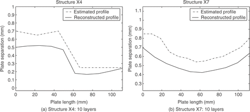
Eight structures (denoted by X1,… ,X8) were manufactured. Of the eight structures X1 to X4 had a step geometry () and X5 to X8 had a tapered form ().
Estimates of the electrical properties are given in . This information was employed to generate simulated reflection coefficients to test the ability of the multilayered model to recover the parameters.
Table 3. Electrical property estimations for connector, structure and termination.
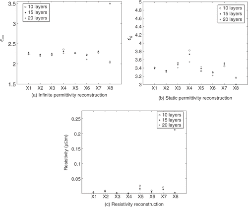
The electrical properties were chosen randomly from a uniform distribution which lay within 5% of those given in . The recovered plate separation profiles were excellent although as the number of layers increases some oscillations started to appear. The recovery of the electrical properties was in general satisfactory with the stepped geometries being more amenable to this recovery than those from the tapered structures. The recovery of the resistivity was less encouraging with the recovered value varying markedly with the number of layers used. The main problem with the resistivity recovery is that the resistivity term only contributes to the cost function over a relatively limited frequency range and so the cost function is dominated by the contribution from the connector terms. One solution may be to initially assume the line is uniform, solve for the connector parameters first, without generating a complete solution for all the line parameters, and then solve for the line including the resistivity.
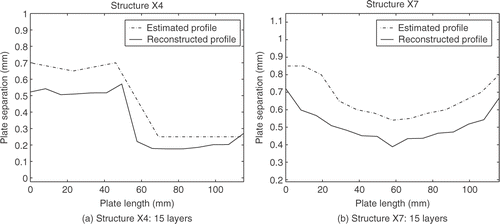
The experience gained from the simulated data was then utilised in the recovery of the same parameters from experimental data. The reconstructed geometric profiles clearly show the geometry as being tapered or step-like (). However, it can be seen that the reconstructions consistently underestimate the plate separation, which may suggest that the adjustment of another parameter may remedy this.
As before with 15 layers the reconstructions were not quite as smooth as they were for the 10 layer model (). The range of permittivities which are recovered are certainly feasible on physical grounds, with the static permittivity reconstruction being slightly high (). There is also some unexpected variation between the different test pieces. Interestingly the number of layers used to reconstruct the geometry does appear to have an effect on the reconstruction of the electrical parameters. The low value which is recovered for the resistivity of the aluminium seems unrealistically low [see , plot (c)]. It also varies from one test piece to another and it is possible that there is a link between this underestimation of the resistivity and the overestimation of the static permittivity. For more results and greater detail the reader is referred to Citation5 and Citation10.
6. Conclusions
This article has been concerned with the integrity of bonded aircraft structures. By assuming transmission line theory on a multilayered structure a forward model for the reflection coefficients was developed. In any practical situation measurement of these reflection coefficients requires a measuring device and a connection to the aircraft structure. This connector therefore needs to be modelled and its associated electrical parameters identified. In this article, we have concentrated on an air-filled line to test the feasibility of the inverse solver in reconstructing the parameters associated with the line and the connector. Having demonstrated the efficacy of the inverse solver we turned our attention to the dielectric-filled line and the multilayered model. The connector was remodelled to take account of the fact that in a real situation it would be clamped to an aircraft structure and the full inverse problem was solved both for simulated data and experimental data.
The results demonstrate the effectiveness of this approach in recovering the spatial parameters associated with an adhesively bonded structure. Reconstructions of the plate separation were shown to be consistently underestimated in comparison with the experimental measurements. More serious was the resistivity which was substantially overestimated; the static permittivity reconstruction was also felt to be a little on the low side. From extensive simulations it appears that the resistivity term only contributes to the cost function over a relatively limited frequency range and so the cost function becomes dominated by the contribution from the connector terms. Our current work is focussing on initially assuming that the line is uniform, solving for the connector parameters first, without generating a complete solution for all the line parameters, and then solving for the line including the resistivity. The VNA performs a synchronous detection of its own signal and we have found that the relatively low levels of noise which arise in a practical situation do not pose any difficulties for the method. There is a further level of uncertainty which arises through the calibration standard of the analyser but we have found that the results were very similar when various analysers with differing calibration standards were utilised. Thus this article presents a feasible and practical method of non-destructive examination of in situ adhesively bonded aircraft structures.
Acknowledgements
The authors would like to acknowledge funding both from the UK EPSRC (Grant GR/N02207) and the USAF (Contract number F61775-01-C00005).
References
- Affrossman, S, Banks, WM, Hayward, D, and Pethrick, RA, 2000. Non-destructive examination of adhesively bonded structures using dielectric techniques: review and some results., Proceedings of the Institution of Mechanical Engineers 214 (2000), pp. 87–102.
- Pethrick, RA, 2000. Comprehensive Composite Materials. Vol. Vol. 5. Oxford and New York: Pergamon; 2000.
- Joshi, SB, Pethrick, RA, Gilmore, R, Yates, LW, and Hayward, D, 1997. Environmental ageing of adhesively bonded joints. I. dielectric studies., Journal of Adhesion 62 (1997), pp. 281–315.
- Joshi, SB, Pethrick, RA, Gray, TF, Banks, WM, Gilmore, R, Yates, LW, and Hayward, D, 1997. Environmental ageing of adhesively bonded joints. II. mechanical studies., Journal of Adhesion 62 (1997), pp. 317–335.
- Mackay, C, Hayward, D, Mulholland, AJ, Mckee, S, and Pethrick, RA, 2005. Reconstruction of the spatial dependence of dielectric and geometrical properties of adhesively bonded structures., Journal of Physics D: Applied Physics 38 (2005), pp. 1943–1949.
- Norgren, M, and He, S, 1996. An optimization approach to the frequency-domain inverse problem for a nonuniform, LCRG transmission line., IEEE Transactions on Microwave Theory and Techniques 44 (1996), pp. 1503–1507.
- Ramo, S, Whinnery, JR, and Duzer, T, 1994. Fields and Waves in Communication Electronics. New York: John Wiley; 1994.
- Havriliak, S, and Negami, S, 1966. A complex plane analysis of α-dispersions in some polymer systems., Journal of Polymer Science: Part C 14 (1966), pp. 99–117.
- Davidson, D, and Cole, R, 1951. Dielectric relaxation in glycerol, propylene glycol andn-propanol., Journal of Chemical Physics 19 (1951), pp. 1484–1490.
- Mackay, C, 2004. "An inverse methodology for the reconstruction of spatial dielectric properties using frequency domain reflection coefficients". In: PhD thesis. Glasgow, UK: University of Strathclyde; 2004.
- www.amphenolrf.com/products/typen.asp, .
Appendix
The Riccati difference equation (3) reduces to
(23)
when
(24)
and
(25)
Performing the transformation results in the linear second-order difference equation
(26)
which may be solved to give
(27)
where
Transforming back to the original variable gives
(28)
where
Now, if r0 is known we may solve (A10) (with m = 0) for C3 to obtain
(29)
after some manipulation using (A1), (A2), (A3) and (A8). Substituting (A8) into (A10) and writing the expression over a common denominator yields
(30)
(31)
using (A1), (A2) and (A12). Further simplification results in
(32)
