Abstract
Anomaly detection is a technique to visualize the interior from the data measured on the ground surface for geophysical applications. The application can be used from oil field prospecting to land mine searching. We have developed the direct inversion algorithm for electrical impedance tomography based on dual reciprocity boundary element modeling, first for the two-dimensional field, which is here extended to three-dimensional field cases. The validation has been made for cases when impedance data are available for electrical current emanation diagonally injected to the surface surrounding the field of interest [Kagawa, Y., Sun, Y. and Zhao, Y., 1997, Direct inversion algorithm for electrical impedance tomography using dual reciprocity boundary element models. Inverse Problems in Engineering, 15, 217–237; Horikane, T., Hataya, T., Xu, W., Zhao, Y. and Kagawa, Y., 2002, 3D electrical impedance prospecting simulation based on dual reciprocity boundary element modelling. In: M. Tanaka and G.S. Dulikravich (Eds) Inverse Problems in Engineering Mechanics III (Amsterdam: Elsevier Science), pp. 411–418.] In practical prospecting, however, this is not always the case, as data are not always available for all surfaces. The present simulation includes the case of anomaly detection when the data are only available on the ground surface.
1. Introduction
Anomaly detection is an important area of geophysical sensing, from oil field to land mine searching. This is a technique to visualize the interior from the data remotely sensed over the surface. This is an inverse problem in Laplace/Poisson fields, whose mathematical background and the uniqueness of the solution have been established Citation3. Electrical impedance sensing is one of the oldest techniques for geophysical exploration and yet plays an important role among others as it only requires a relatively inexpensive apparatus, and is widely practiced Citation4–6. Tomographic imaging was attempted with impedance data for diagonal current injection with boreholes provided Citation7. This model ignores that the current is diffusive and does not flow straight but in multipaths. For electrical impedance tomography, a finite element modeling was first proposed by Murai and Kagawa Citation8 in which perturbation approach was employed for inversion. The tomographic technique can simply be used for medical care and monitoring Citation9, in which the final goal is of course to achieve the imaging of the body's interior. For experimental purposes, Barber and Brown Citation10,Citation11 developed the apparatus called applied potential tomography (APT), which was once commercially available. The image reconstruction uses the backprojection algorithm similar to the X-ray computed tomography in which the currents are assumed to flow in straight between a pair of current electrodes. Generally, this condition is not appropriate as currents flow through multipaths as previously mentioned. Therefore, in most inversions an iterative approach is used. Equations must be established to satisfy the Ohm's law for the line integral for each assumed path. The direct inversion is thus not possible. Instead, the resistivity distribution is first assumed and then iteratively modified so as to minimize the error function defined as the norm between the potentials observed for a certain current injection and the potentials evaluated for the above equations for a model with assumed resistivity distribution chosen as design variables Citation4–6,Citation12. This is time-consuming particularly for three-dimensional (3D) models. With the present direct inversion, the distribution is obtained without iteration. The advantage of the present approach over conventional techniques is that as no internal discretization and iteration are required, the solution is very efficient.
We successfully developed the direct inversion algorithm for electrical impedance tomography based on dual reciprocity boundary element models in two dimensions Citation1. The modeling and algorithm were then extended to the 3D field Citation2. Here, the demonstration is made for two cases of current injection. One is the case when boreholes are provided to obtain impedance data partially for diagonal current injection like in ref. Citation7. This injection condition is somewhat similar to the so-called opposite method Citation9. Another case is when data are only accessible on a single (ground) surface. This condition is somewhat similar to the so-called neighboring method Citation9. Many electrical impedance imagings only consider the cross-section of the field taken in 3D, in which current flow is assumed to stay in the cross-sectional plane. This again is not true, as the current field is diffusive, and the current paths take them out of the plane, which should not be ignored. Therefore, 3D modeling is essential, as in the present case.
2. Field and boundary element modeling
2.1. Nonhomogeneous field expression
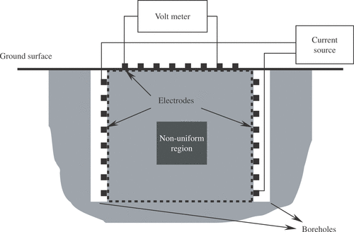
The present study is to visualize the conductivity distribution in a 3D field of interest from data collected between the electrodes placed on the ground surface and boreholes. The cross-sectional view of the field is depicted in . The currents flow least outside of a cubic region closed by dotted lines, in which an anomaly is assumed to be buried. This region is only considered for analysis with proper boundary conditions imposed without losing the generality. The conductive nonhomogeneous space is governed by the Laplace equation
(1)
with boundary conditions
(2)
where ψ is the potential, p is its normal derivative or flux, and σ is the conductivity depending on the spatial position σ =σ (x,y,z). It should be noted that for homogeneous fields when σ is constant, equation (Equation1
(1) ) is
(3)
when the field is not homogeneous, equation (Equation1
(1) ) can be transformed into a Poisson equation of the form
(4)
where
(5)
Thus the Laplace equation for the nonhomogeneous field is transformed into the Poisson-type expression with a distributed forcing term. When the distributions of b and ∇ψ are known, the distribution of σ can be obtained from equation (Equation5
(5) ).
2.2. Dual reciprocity in charge simulation method
Dual reciprocity method (DRM) was first introduced to the boundary element solution of elastic field problems by Nardini and Brebbia Citation13. The boundary element solution of Poisson equation involves the domain integral in association with the forcing term. The presence of the inhomogeneous term destroys the merit with the boundary only nature in boundary element method. The DRM is a relief of the symptom, which removes the domain integral at the expense of the introduction of the particular solutions. The procedure is exactly the same as that in ref. Citation1 except that the problem is now three dimensional Citation2. The solution of equation (Equation4(4) ) can be expressed in terms of a linear combination of the general solution of the homogeneous Laplace equation and the particular solution of the Poisson equation, so that
(6)
where ϕ is the fundamental solution of ∇ 2ϕ =0 and φ is the particular solution of ∇ 2φ =b. Substituting equation (Equation6
(6) ) into equations (Equation4
(4) ) and (Equation2
(2) ), one obtains the equation
(7)
with the boundary conditions
(8)
Equation (Equation7
(7) ) is the Laplace equation and boundary element discretization leads to the linear algebraic expression of the standard form
(9)
where [K ] and [G] are a system and its companion matrices, and {φ} and {∂φ/∂n} are the potential and flux vectors associated with the nodes taken on the boundary. The boundary surface is divided into M elements, for which N boundary nodes and L internal points are considered. The potential ψi at an arbitrary point i can be expanded as
(10)
is the fundamental solution of the homogeneous equation ∇2φ =0, which is evaluated at point i for a unit source excitation at point j on the boundary (j=1,2,…,M). Coefficient βj therefore corresponds to the fictitious charge associated with the boundary element j.
is the particular solution of the Poisson equation
(11)
The essence of DRM lies in the expansion of the forcing term in terms of the approximate function fiℓ arbitrarily chosen, so that
(12)
In matrix form,
(13)
where the component of [F] is Fiℓ=fiℓ. Following ref. Citation13, the approximate function is here chosen to be
(14)
where riℓ is the distance between the source point i and the point of consideration ℓ, and rmax is the maximum distance. The particular solution that satisfies equation (Equation11
(11) ) is
(15)
when the second function of equation (Equation13
(14) ) is used. It should be noted that equation (Equation14
(15) ) is different from the expression for the two-dimensional (2D) case Citation1.
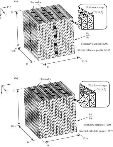
The surface is divided into triangular elements and nodes are taken at the element corners and fictitious or simulated charges are placed at the centers, which are shown in .
Figure 2. 3D cubic field (a) Electrodes on five surfaces (on the top surface corresponding to the ground surface). (b) Electrodes on the surfaces (only on the top surface).
The fundamental solution of the homogeneous equation is
(16)
where rij is the distance between two points i and j, that is
where
which is also different from that of the 2D case. Coefficient βj corresponds to the fictitious charge placed at point j. Equations (Equation8
(8) ) and (Equation12′
(13) ) are substituted into equation (Equation9
(9) ) and in the end, the discretized equation for the Poisson equation is obtained as follows:
(17)
where
(18)
and
(19)
The definitions of the matrices components are
(20)
(21)
and, when the constant elements are used,
(22)
2.3. Direct inversion
Equation (Equation16(16) ) is solved for {α} under boundary conditions and the potential data {ψ} “measured” on the boundary, and for the boundary condition {∂ψ/∂n} when the current is injected between a pair of chosen electrodes. {b} is obtained with help of equation (Equation12′
(13) ). When
is known for the kth measurement, equation (Equation5
(5) ) can be written as
(23)
where R is the logarithmic resistivity coefficient defined by
, (
and
is the slope of R in x-direction about point i.
is the potential at point i, and
is the potential gradient in the x-direction about point i in the domain. The potential ψi and its gradients
and
in arbitrary point i are evaluated by equation (Equation10
(10) ) as {α} and {β} are now known from equation (Equation12′
(13) ) and (Equation18
(19) ). In equation (Equation22
(23) ), the three slopes of the logarithmic resistivity coefficient are unknowns while ψi and its three-directional slopes are now known. One has three equations of the form of equation (Equation22
(23) ) for the three times of “the measurements” (k=1,2, and 3) with a different current injection pair, which must be solved.
When the field is isotropic and the slope is the same for each direction, or , the solution is theoretically obtained for the data in a single measurement. In a practical situation, we establish as many equations for the measured potential data as the times of different injection. These simultaneous equations are then over-determined, which can be solved in the least square sense.
3. Numerical demonstration
For the test case, a region closed by a dotted line is used for simulation and is depicted in . It is a cubic field (103 m3) as shown in . The surfaces are divided into the triangular elements. Two cases are considered. One is when the electrodes are placed on the top surface (corresponding to the ground surface) and other four surfaces in boreholes, . Another is the case when the electrodes are placed only on the top surface, . As current is applied between a pair of the electrodes, the current leaking out of the cubic region will be very small. The natural boundary condition can thus be set except the amount on the electrodes. The first case is when a cubic anomaly (23 m3, conductivity is 10/% higher) is buried in the middle. What is obtained is not the conductivity or resistivity but their gradients. The logarithmic resistivity coefficient could be obtained by integrating the solutions , and
for a cubic pixel i along x-, y- and z-directions. What we are concerned about here is not the magnitude but its relative value in order to visualize the distribution. In the present test, for the “measured” data, the solution of the forward problem is used. The simultaneous equations are formed for the injections of every possible pairs of electrode combination.
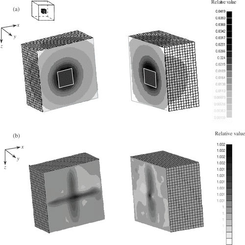
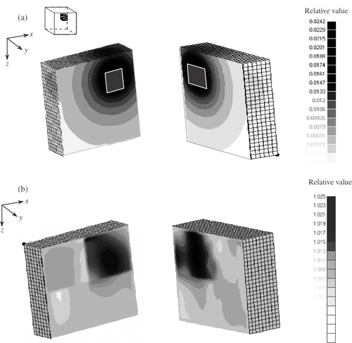
shows the result when electrodes are provided on the top surface (ground surface) and the surrounding four surfaces (boreholes) to sense a cubic object with higher conductivity by 10%, placed at the central part of the region of interest. shows a potential change distribution referring to that of the homogeneous field for the same current injection. shows the relative conductivity distribution inverted by the present algorithm. shows the same case except the object is placed at one of the corners. The cross-sectional shapes of the object inverted are not exactly the same as that of the original cubic. The visualized figures clearly show the presence of the object in both its location and size. Blurred figures of the object must be due to the fact that the distribution function used is continuous in our formulation, while the discontinuous conductivity is set in the simulation.
Figure 3. Electrodes on five surfaces, a nonhomogeneous cubic region (conductivity 10% higher) is placed in the middle. (a) The distribution of potential change (in planes y = 3.0, x = 7.0). (b) The relative conductivity distribution inverted (in planes y = 3.0, x = 7.0).
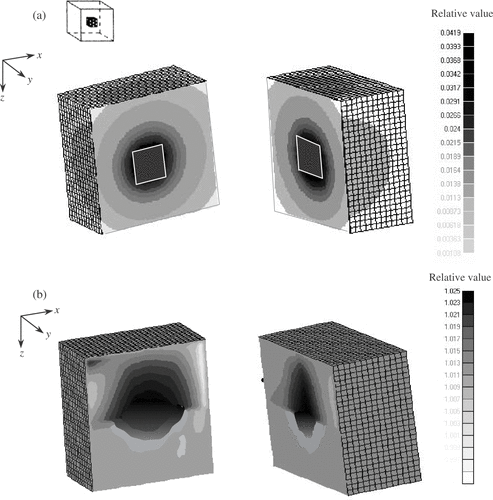
Figure 4. Electrodes on five surfaces, a nonhomogeneous cubic region (conductivity 10% higher) is placed in one of the corners. (a) The distribution of potential change (in planes y = 3.0, x = 7.0). (b) The relative conductivity distribution inverted (in planes y = 3.0, x = 7.0).
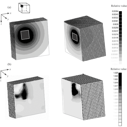
and show the cases when the sensing is made only on the top surface. We see conductivity higher than 10% in that the quality is poorer but the location is clearly presented.
4. Conclusion
The direct inversion algorithm is extended to 3D electrical impedance tomography and the numerical simulation is demonstrated successfully for two cases. The numerical demonstration shows that the inverted distribution is capable of identifying the position of an anomaly but the resolution is rather poor, particularly when the data are only accessible on the ground surface. The additional data on the surfaces surrounding the region with the boreholes drilled down into the ground gives better result.
The purpose of the present article is to confirm the capability of the anomaly detection buried under the ground surface. No further investigation, such as the minimum number of the electrodes or sensitivity analysis are included. Computation time required for the inversion is about an hour on a PC. We believe that the inverted data can be used at least for initial guess data for the repetitive optimization approach, if they are poor.
In the present noise-free simulation, no trouble is experienced in performing the inversion. However, in a real situation, the measured data are apt to be contaminated by noise and the inverse problem is generally ill-posed, in which the uniqueness and stability are also the important issues for reasonable solution. They have been experienced in our previous works Citation8,Citation14,Citation15 and their remedies have been discussed to remove them, which is why we have not included them in the present paper.
References
- Kagawa, Y, Sun, Y, and Zhao, Y, 1997. Direct inversion algorithm for electrical impedance tomography using dual reciprocity boundary element models, Inverse Problems in Engineering 15 (1997), pp. 217–237.
- Horikane, T, Hataya, T, Xu, W, Zhao, Y, and Kagawa, Y, 2002. "3D electrical impedance prospecting simulation based on dual reciprocity boundary element modelling". In: Tanaka, M, and Dulikravich, GS, eds. Inverse Problems in Engineering Mechanics III. Amsterdam: Elsevier Science; 2002. pp. 411–418.
- Kohn, RV, 1984. Identification of an unknown conductivity by means of measurements at the boundary, American Mathematical Society, SIAM–AMS Proceedings 14 (1984), pp. 1–9.
- Shima, H, Kajima, K, and Kamiya, H, 1995. Resistivity image profiling. Tokyo: Kokin-Shoin; 1995, (in Japanese).
- Apporas, A, 1997. Developments in Geoelectrical Methods. Rotterdam: A.A. Balkema Pub.; 1997.
- Patra, HP, and Nath, SK, 1999. "Schlumberger Geoelectric Sounding in Ground Water, Principles". In: Interpretation and Application. Rotterdam: A.A. Balkema Pub.; 1999.
- Dines, KA, and Lytle, JR, 1979. Computerized geophysical tomography, Proceedings of the IEEE 67 (1979), pp. 1065–1093.
- Murai, T, and Kagawa, Y, 1985. Electrical impedance computed tomography based on a finite element model, IEEE Transactions on Biomedical Engineering BME–32 (1985), pp. 177–184.
- Webster, JW, 1990. "Electrical impedance tomography". In: Adam Hilger Series on Biomedical Engineering. Bristol: Adam Hilger; 1990, (Ed.).
- Barber, DC, and Brown, BH, 1983. Imaging spatial distributions of resistivity using applied potential tomography, Electoral Letters 19 (1983), pp. 933–935.
- Brown, BH, Barber, DC, and Seagar, AD, 1985. Applied potential tomography: clinical possible applications, Clinical Physics and Physiological Measurement E (1985), pp. 109–121.
- Murai, T, and Kagawa, Y, 1986. Boundary element iteration techniques for determining the interface boundary between two Laplace domains – a basic study of impedance plethysmography as an inverse problem, International Journal of Numerical Methods for Enggineering 23 (1986), pp. 35–47.
- Partridge, PW, Brebbia, CA, and Wrobel, LC, 1992. The dual reciprocity boundary element method. Southampton: Computational Mechanics; 1992.
- Murai, T, and Kagawa, Y, 1981. A finite element model for the inverse problem in electrocardiography, Transactions of IECE, Japan, ' 81/1 J64–C (1981), pp. 1–8.
- Murai, T, and Kagawa, Y, 1982. An approach for regularizing the ill-condition associated with inverse cardiographic problem, Transactions of IECE, Japan, '82/5 J65–C (1982), pp. 359–366.
