Abstract
The objective of this study is to combine dynamic mesh technique and heuristic algorithms [Vibrational Genetic Algorithm (VGA)] to improve aerodynamic design of a wing, in order to see the effect of thickness ratio constraint when it is taken into the design parameters, additionally to reduce the drag values as much as possible while holding the lift value fixed. To solve the flow field around the 3D models obtained during the optimization stages, the mesh required is generated by dynamic mesh technique. The code developed for this aim is robust and faster than the codes, which only produce mesh by classical techniques. Because the operating time of the code is very long, on account of our low capacity computer resources, parallel processing has been used. Obviously, the strategy applied here can be used for any slowly deforming complex geometries, as long as an effective combination of the genetic algorithm and dynamic mesh be succeeded. From the results, it is observed that the optimization process is working as expected. The inviscid drag was reduced by about 25%.
1. Introduction
There are two common strategies in engineering optimizations, gradient-based and gradient-free. Genetic algorithm (GA) and search algorithm (SA) are gradient free methods. But they require large number of function evaluation. On the other hand, gradient-based methods require far fewer function evaluations as long as accurate gradient information is available. In the most general sense, optimization is the process of achieving the best outcome of a given operation while satisfying a set of given constraints. The cost (or objective) function is the term applied to this outcome that needs to be improved (or optimized) Citation1. In general, for aerodynamic design problems, stream function-based methods Citation2, numerical optimization Citation3 or control theory Citation4 are used. As compared with transonic flows, supersonic flows are considered well-behaved and more stable because the problem of the shock at the wall is eliminated Citation5.
Quiet supersonic platform (QSP) program Citation6 is an example problem requiring multidisciplinary design optimization (MDO), in which the noise level of the ground boom signature of a supersonic business jet should be significantly reduced while challenging and aerodynamic performance requirements must be met at the same time.
The time-consuming flow solvers and gradient type optimization techniques have not recently been preferred. Instead, flow solvers are carried into parallel computing type machines and optimizations are carried out by evolutionary techniques. Citation7
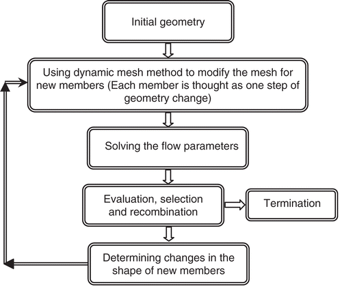
Algorithms based on these techniques are entering in many engineering fields Citation8, since the technique used in these types of algorithms is inherently and quite naturally based on natural selection rules, mutation, crossover, elitism, etc. developed by Darwin. General structure of genetic optimization is outlined in .
In this study, Onera M6 wing has been optimized by using vibrational genetic algorithm (VGA) Citation9–11. Here, we tried to minimize the drag force while the lift force and/or the thickness ratio have been held fixed by using a lift and/or a thickness ratio value constraint in the fitness function formula. For the 3D models developed during the optimization stages, the required mesh was generated by the dynamic mesh technique Citation12, Citation13. The code developed for this aim is robust and faster than the codes, which only produce mesh by classical techniques Citation14.
The population members are obtained by modifying the previous ones, each member is considered as one step of geometry-change of a deforming body, for example a wing inflating, deflating or cambering. Obviously, the strategy applied here can be used for any slightly deforming complex geometries, as long as an effective combination of the GA and dynamic mesh succeeds.
Force calculations were done by using a finite element method Citation15. The pressure value for each triangular wall boundary face is taken as the average of the pressures on the corner nodes. Then the total forces are calculated by a numerical integration.
2. Flow solving method
‘Acer3D’ is a flow solver program, which solves inviscid compressible Euler flow equations on unstructured tetrahedral grids. Serial and parallel versions together with parallel adaptive sensor program were developed in a PhD thesis study by Erdal Yılmaz Citation16, Citation17.
If U is a vector quantity per unit volume acting in an arbitrary volume Ω, fixed in space and bounded by a closed surface S. The local intensity of U changes according to the effect of fluxes and sources. F, the flux vector, has two components, the convective part and the diffusive part.
The sources can be thought as volume and surface sources. Hence the general form of the conservation equation for U is given as follows Citation18:
(1)
If no surface and volume sources exist, then the right hand side of the equation (1 vanishes. For compressible Euler equations, equation (1 takes the form:
(2)
where U is called the solution vector and represents the conserved quantities and F is the flux vector with
(3)
In these equations f, g, and h are components of the flux F in Cartesian coordinates, ρ is density, u, v, and w are Cartesian velocity components, p is pressure, H is total enthalpy, and E is total energy per unit mass and
(4)
The Euler equations are discretized in space by using the finite volume formulation Citation18 which is based on the application of integral form of the balance laws. In numerical solution, each cell or element that defines the physical domain is treated as a finite volume. The conservative discretization is achieved by applying the integral form of the Euler equations at the level of each elementary cell Citation16.
The boundary condition needed for inviscid flows at surfaces of the object is the flow tangency or zero velocity at the normal direction to the boundary. This is achieved by assigning zero to the convective fluxes along all mesh faces at the surface of the object during the initial iterations. The symmetry surface is thought as inviscid wall boundary condition. Therefore, only the normal velocities are set to zero at boundary faces.
The flow conditions are:
| • | Mach number: 0.84 | ||||
| • | Angle of attack: 3.04 | ||||
| • | Initial (starting) model: onera M6 wing | ||||
| • | Thickness ratio: 9.79243E−02 | ||||
| • | Taper ratio: 0.562315 | ||||
| • | Original (Design) lift force (calculated from non-dimensional pressure values): 3.278321E−03 | ||||
| • | Original drag force (calculated from non-dimensional pressure values): 7.386871E−02 | ||||
| • | Original (design) lift coefficient: 0.2841 | ||||
| • | Original drag coefficient: 0.0126 | ||||
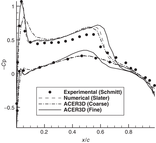
As an example of the solutions of Onera M6 wing, the pressure coefficient distribution comparison at the station 20% is shown in .
3. Dynamic mesh techniques in heuristic algorithms
In the field of aerodynamics, the inviscid type of modeling, the dynamic mesh technique has been applied to the unsteady Euler airfoil solutions and the unsteady Euler algorithm for complex aircraft aerodynamic analysis by Batina Citation12, Citation13.
By using the dynamic mesh technique, the original mesh can be modified to fit the change in angle of attack or, for instance, the change in the shape of an aircraft fuselage. In GA, for example, the dynamic mesh method is used to modify the mesh to fit the change in twist angle Citation7.
Therefore, in this study, dynamic mesh method is implemented on a real coded GA to demonstrate gain in computational time as well as in higher performance for optimized parameters Citation19Citation20.
4. The vibrational genetic algorithm: description and verification
GA are developing procedures. They resemble Darwin's theory of evolution, which claims that a biological population adapts to its environment by selection, crossover and mutation.
GA is a non-gradient method Citation21 that offers a promising answer to complex optimization problems. In general, a GA is broken into three major steps: evaluation, crossover and mutation. An initial population of complete design variable sets is analyzed according to some cost function. Then this population is merged using a crossover and mutation methodology to create a new population. This process continues until a global minimum is found.
The VGA Citation9 is a GA that uses the vibration concept. In that, by applying a vibrational mutation periodically to all individuals in a population, they are spread out over the design space. Therefore, it becomes possible to escape local optimums and thus to obtain a global optimum faster. Hacioglu and Ozkol Citation9–11 have developed its procedures on especially 2D airfoils and called it as VGA. VGA has also been used for solving continuous covering location problems by Ermiş et al Citation22.
Previous works about vibration concept were presented by Hacioglu and Özkol Citation9, Citation10. They first introduced Double Directional Alpha Method which is named as vibrational crossover in their later study. The vibration concept was presented as vibrational crossover and vibrational mutation in Citation9.
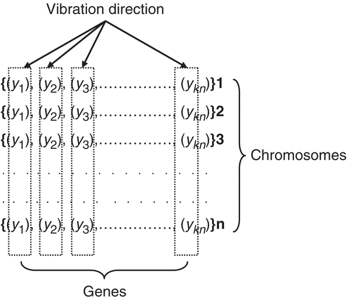
Vibration strategy in mutation is used after a recombination. Entire genes in all the chromosomes are mutated through vibration wave as follows,
(5)
where
are the control points (genes), kn is the chromosome length (total gene number of a chromosome), n is the total number of individual in the population, MA is the main amplitude, u is a random real number between (1, 0), and w1 is a user defined real number between (0, 2) and controls MA. kn is taken as 13 meaning that there are 13 control points as the design parameters for representing each side of the wing section. Two of them are fixed as leading and trailing edge points. Therefore, there are 22 design variables for both sides of the wing section. These control points are converted into airfoil points by using Bezier curve method.
Implementation of the vibrational mutation starts from a certain gene position at first chromosome, and continues throughout the genes at the same positions in the other chromosomes as shown in . This process is applied to all the individuals in the population every IP generation (period) where IP is an integer number. So, each individual in the population is mutated one time for every IP generation. Consequently, the mutation rate Pm has to be equal to 1/IP. Actually, Pm is not used for vibrational mutation. That is, there is no need to define Pm. However, IP is related to Pm to indicate how much the mutation is implemented during the GA process.
Since a random distribution in a narrow band helps in reaching the global maximum as close as possible, the main amplitude MA is evaluated during the genetic process as follows:
(6)
where AF0 and AFk are average fitness values at the initial and current generations of the genetic process respectively, and r is a real number.
A brief verbal description of the vibrational mutation procedure can be given as follows: at the first step of genetic process, after the recombination phase, vibrational mutation is applied to all new chromosomes. First, initial genes (j = 1) in all chromosomes (i = 1, … , n) are vibrated; after that, the genes at the second position (j = 2) in all chromosomes (i = 1, … , n) are vibrated. This operation ends when the last genes (j = kn) are vibrated as shown in . At next IP − 1 steps (generations) of the genetic process, regular GA operations (evaluations of fitness, selection and recombination) are performed. So, mutation rate Pm = 1/IP. At the IP + 1 th generation, vibration is applied just like at the first step. Vibration implementation is repeated at (1st, IP + 1, 2IP + 1, 3IP + 1, …) generations (every IP step), while the genetic process goes on.
Experiments were performed for three different cases in Hacioglu and Ozkol's thesis Citation10. In the first, inverse airfoil design in incompressible, inviscid flow and airfoil optimization in transonic flow have been performed.
Surface pressure coefficient distribution, Cp, of NACA4412 airfoil at 10° angle of attack is given for inviscid, subsonic, incompressible flow. The Computational Fluid Dynamics (CFD) method is vortex panel technique for incompressible, inviscid flow. A total of 120 panels have been used for CFD calculations.
Following strategies are used for genetic operations for the case above:
Regular genetic algorithm (RGA): Crossover technique is BLX-α Citation23 with α = 0.7 (the best value for this case), Pm = 0.015. VGA will not be used. Mutation is applied to randomly chosen ith gene in kth chromosome which is selected randomly in the population, by using the following formula:
(7)
Vibrational genetic algorithm (VGA): Crossover technique is BLX-α with α = 0.7, additionally vibrational mutation with new formulations, in equation (5), is used. For applications, w was taken as 0.04 for all case.
The selection method is stochastic universal sampling Citation24. It is started from the NACA 0012 to reach the desired airfoil for inverse design. The thickness ratio of NACA 0012 is changed ±30% uniformly in the initial population. In optimization case, it is started from the original airfoil (NACA 0012) exactly to reach the optimized one.
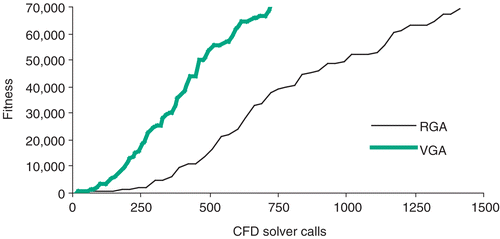
In inverse design applications, for vibrational mutation, the value of r in equation (6) was taken as four. For the applications, 70,000 are good enough as the fitness value for the fast convergence. The results presented are the average value of 10 different experiments. In , plotted horizontal axis shows number of CFD calculations and the vertical axis, and fitness values which correspond to each CFD calculations.
Discussion: RGA is applied for the population size n = 30. In the application of VGA, as in the previous study Citation9, a small population size is more convenient. The population size for VGA application is n = 12, for the vibrational mutation IP = 3 (Pm = 1/3) is chosen. The value of w1, in equation is 1.0. shows the comparison of best fitness values for two different strategies. The figure reveals that in each technique proposed by us, VGA has comparatively faster convergence than RGA. To obtain target fitness value, for RGA 1440 and for VGA 732 CFD calculations are needed. Comparing these CFD calculations to the regular case indicates that in the VGA case 49% reduction is observed.
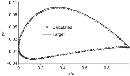
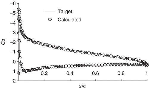
shows the target profile geometry and optimized one by the inverse design. Similarly, depicts pressure coefficients for the relating geometries. These two figures clearly indicate the excellence of the implemented method for the inverse airfoil design problem in incompressible, inviscid flow.
The numerical applications indicate that VGA has a great impact on the number CFD calculations for the inverse airfoil design Citation10. This method is not only working for incompressible subsonic flow condition but transonic as well. If we would like to talk in numbers, for the sake of comparison, number of CFD calculations is reduced about more than 45%. For the engineering problems, especially inverse airfoil design and optimization Citation10, this method seems to be promising.
Finally, VGA applications, either combined or individual, result in a tremendous reduction in CFD calculation or CPU time. And it is also possible to use these strategies in many other engineering problems Citation8.
5. 3D optimization results
5.1. Progress in generations
In the optimization process, there are 14 members in each generation. These are 14 Onera m6 wing planforms that have different wing sections. All of them are solved by ACER3D Citation16, Citation17 and their lift and drag forces are calculated.
By using these forces, fitness values are calculated for each member. The fitness function is taken as:
(8)
(9)
| CD | = | Drag coefficient calculated; |
| CL | = | Lift coefficient calculated; |
| CLd | = | Design lift coefficient; |
| a | = | Constant parameter to define the weight of the lift coefficient constraint; |
| Th | = | Thickness ratio of the produced wings; |
| Thd | = | Design thickness ratio; |
| b | = | Constant parameter to define the weight of the thickness ratio constraint. |
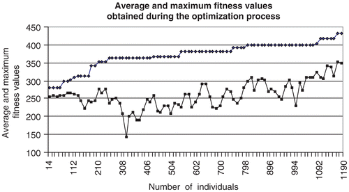
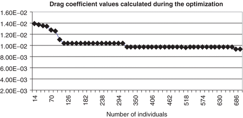
The average fitness value for each generation and the maximum fitness value (i.e. the best member found in that generation) are shown in . Improvement in the drag coefficients during the optimization is illustrated in .
The best member is kept in each generation and taken to the next generation. So the best member found in each generation cannot be worse than the best member of the previous generation. It can be at least the same as the previous one.
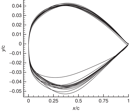
In the following stages, the wing sections are reproduced according to their fitness ratios based on the genetic processes (crossover, mutation, etc.). The wing sections found in the 50th generation are shown in .
It can be thought that decreasing the drag force without holding the thickness ratio and letting the wing section become thinner is an easy way of this kind of work. However, this application has been performed to see if the optimization process is working as expected. After this application, the optimization process is implemented with a thickness ratio constraint.
5.2. Change in mesh structures
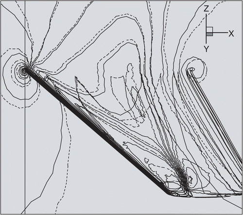
The unstructured tetrahedral mesh is modified according to the change in the wing section by using dynamic mesh technique and for all members of each generation; new mesh structures have been calculated. For instance, the meshes calculated for two different wing sections are shown in . As it can be seen from this figure, the differences between the two mesh structures are very small compared to the wing size. This is quite normal.
Figure 10. The mesh structures of the first and the best wing found at the 50th population (initial: dashed line, 50th: solid line).
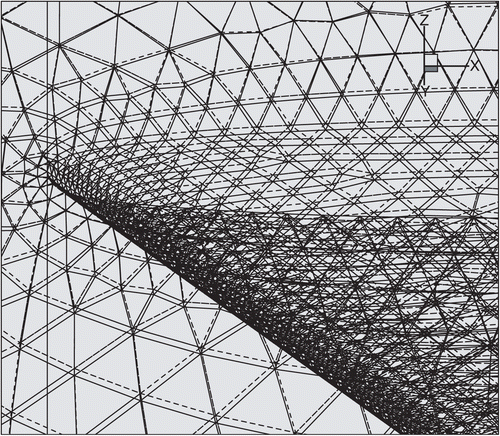
Because the process has some constraints like constant lift force and thickness ratio, the large changes in geometry are prevented.
5.3. Change in pressure coefficients
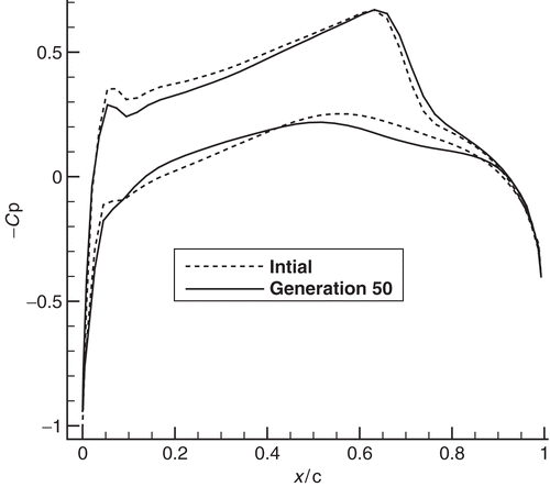
In , the differences between pressure coefficient distributions of the initial wing and the best member produced in the 50th generation can be seen. In , the pressure coefficient distributions over the root sections at different stages are illustrated.
5.4. The best wing sections found by genetic processes
In , the best members obtained in different stages with and without thickness ratio constraint are shown. If the wing sections found are compared, it can be seen that the wing section has become thinner without thickness ratio constraint. This is quite natural, since in the pressure calculations, thickness ratio has a dominant effect which influences shock strength. If this ratio has not been held fixed it continuously reduces to zero value. During this process it was tried that the lift coefficient was held fixed, while the drag coefficient was reduced by 25%.
Figure 13. Wing sections of the first and the best members found at the later stages (with and without thickness ratio constraint).
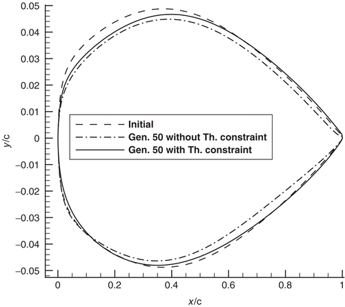
As it can be seen in , the thickness of the wing is a little lowered even with a thickness ratio constraint. This is avoidable by adjusting the weighting constant (i.e. “b”) of the thickness ratio in the fitness function. However, there would be a cost for this. More generations would possibly be needed to achieve a good solution.
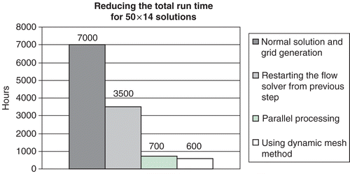
CPU times are dependent on the computer resources, both the hardware and the software. Especially in GA because of the selection and mutation processes each application may not give exactly the same result. Therefore, the improvements in the CPU times may not occur at the same level in each application, especially in GA. An example of CPU time improvement is shown in . These hours are valid for a 1.3 GHz P IV computer and 360,000 element tetrahedral mesh structure.
6. Conclusion
The CPU time of the first step in dynamic mesh method is approximately the same as regular mesh generation time. However, later steps of dynamic mesh technique need much less time than the first step (i.e. about two or three times faster). Therefore, especially, if a lot of configurations are to be considered, the dynamic mesh method offers more advantage.
The number of the short runs required to get satisfactorily accurate results changes between 700 and 3000 for the considered geometry. This means a huge calculation time for 3D geometries. The optimization was designed in parallel processing form, which reduces the computing time at least seven times. By restarting the flow solver from previous solution and using the dynamic mesh technique for re-meshing the new population members, the calculation time is also reduced about four times.
From the results, it is observed that the optimization process is working as expected. The inviscid drag was reduced by about 25% in both cases, with and without thickness ratio constraint. While this has been done, we tried to keep its lift coefficient close to the design value determined at the beginning. This is done by arranging the fitness function. At the 50th generation the discrepancy between the lift coefficient of the best member and the design lift coefficient value is about 1% and the discrepancy between thickness ratios is 3%.
Fifty generations are not necessary to get a sufficient solution. As it can be seen from , the significant part of the improvement in the fitness value can be achieved in 30 steps (i.e. 420 members)
The designer should decide how much important the changes (of course this depends on the problem in hand and purposes) in these constraints are. If they are to be kept in certain ranges at the design values more strictly, then the weighting constants in the fitness function should be increased.
However, the cost of this would be higher number of iterations to achieve a good solution.
Acknowledgments
For the computations, the authors thank Informatics Institute of Istanbul Technical University.
References
- Foster, NF, and Dulikravich, GS, 1997. Three dimensional aerodynamic shape optimization using genetic and gradient search algorithms, Journal of Spacecraft and Rockets 34 (1) (1997), pp. 36–42.
- Dulikravich, GS, 1991. Aerodynamic shape design and optimization, Tech. Rep. 91–0476, AIAA paper (1991).
- Vanderplaats, GN, 1984. Numerical Optimization Techniques for Engineering Design: With Applications. New York: McGraw Hill; 1984.
- Jameson, A, 1988. Aerodynamic design via control theory, Tech. Rep. 88–64 (1988), CASE.
- Filippone, A, 2004. Advanced topics in aerodynamics, aerodynamic drag, release 3.8.3 October 1. Manchester M60 1QD United Kingdom: The University of Manchester, Dept. Mechanical, Aerospace, Civil Engineering P.O. Box 88; 2004, http://aerodyn.org/Drag/speed-drag.html#tdrag.
- Chung, HS, 2004. "Multidisciplinary design optimization of supersonic business jets using approximation model-based Genetic Algorithms". In: PhD thesis submitted to the Department of Aeronautics and Astronautics and the Committee on Graduate Studies of Stanford University. 2004.
- Obayashi, S, Nakahashi, K, Oyama, A, and Yoshino, N, 1998. Design Optimization of Supersonic Wings Using Evolutionary Algorithms, ECCOMAS 98. Tohoku: John Wiley & Sons; 1998.
- Ozkol, I, and Komurgoz, G, 2005. Determination of the optimum geometry of the heat exchanger body via a genetic algorithm, Numerical Heat Transfer, Part A 48, (2005), pp. 283–296.
- Hacioglu, A, and Özkol, İ., 2002. Vibrational genetic algorithm as a new concept in aerodynamic design, Aircraft Engineering and Aerospace Technology 74 (3) (2002), pp. 228–236.
- Hacioglu, A, and Özkol, İ., 2003. Transonic airfoil design and optimization by using vibrational genetic algorithm, Aircraft Engineering and Aerospace Technology 75 (4) (2003), pp. 350–357.
- Hacioglu, A, and Özkol, İ., 2005. Inverse airfoil design by using an accelerated genetic algorithm via distribution strategies, Inverse Problems in Science and Engineering 13 (6) (2005), pp. 563–579.
- Batina, JT, 1990. Unsteady Euler airfoil solutions using unstructured dynamic meshes, AIAA Journal 28 (8) (1990), pp. 1381–1388.
- Batina, JT, 1991. Unsteady Euler algorithm with unstructured dynamic mesh for complex-aircraft aerodynamic analysis, AIAA Journal 29 (3) (1991), pp. 327–333.
- Vatandaş, E, Özkol, İ, and Kaya, MO, 2003. "Implementation of the dynamic mesh methods on genetically obtained mesh structures for 3-D geometries. In". In: Proceedings of International Congress on Evolutionary Methods for Design, Optimization and Control with Applications to Industrial Problems. Barcelona, Spain: EUROGEN’03; 2003.
- Mecitoglu, Z, and Dökmeci, MC, 1990. "Vibration analysis stiffened cylindrical thin shell. In". In: Proceedings of 17th Congress of the International Council of Aeronautical Sciences. Stockholm. 1990. pp. 986–993.
- Yılmaz, E, 2000. "A three dimensional parallel and adaptive euler flow solver for unstructured grids". In: PhD thesis. Ankara-Turkey: Middle East Technical University (METU); 2000.
- Yılmaz, E, Kavsaoglu, MS, Akay, HU, and Akmandor, IS, 2001. Cell-vertex based parallel and adaptive explicit 3D flow solution on unstructured grids, The International Journal of CFD 14 (2001), pp. 271–286.
- Hirsch, C, 1988. Numerical Computation of Internal and External Flow. Vol. 1. New York: John Wiley & Sons; 1988.
- Vatandaş, E, Özkol, İ., and Kaya, MO, 2004. Using the dynamic mesh method for genetically obtained wing structures, Aircraft Engineering & Aerospace Technology 76 (3) (2004), pp. 314–319.
- Vatandaş, E, and Özkol, İ., 2006. “Dynamic mesh and heuristic algorithms for the design of a transonic wing”, Aircraft Engineering & Aerospace Technology 78 (1) (2006), pp. 34–44.
- Haftka, RT, and Gürdal, Z, 1992. Elements of Structural Optimization. Boston, MA: Kluwer Academic; 1992.
- Ermiş, M, Ülengin, F, and Hacioglu, A, 2002. Vibrational genetic algorithm (VGA) for solving continuous covering location problems, Lecture Notes in Computer Science 2457 (2002), pp. 293–302.
- Eshelman, LJ, and Schaffer, JD, 1993. Real coded Genetic Algorithms and Interval Schemata, Foundations of Genetic Algorithms 2. San Francisco: Morgan Kaufmann Publishers; 1993. pp. 187–202.
- Baker, JE, 1987. "Reducing bias and inefficiency in the selection algorithm, In". In: Proceedings of the Second International Conference on Genetic Algorithms. San Mateo: Morgan Kaufmann Publishers; 1987. pp. 14–21.
