Abstract
The full Newton's method is considered as an optimisation approach to the inverse transmission line problem in the frequency-domain. For the sake of accuracy and computational efficiency, the gradient and the Hessian of the cost-functional, with respect to parameter functions in the L2-space, are derived explicitly by means of the adjoint transmission line problem and the first and second order Frechét differentials of the cost-functional. The numerical implementation, when reducing to a finite dimensional parameter space, and a regularisation technique for the resulting ill-conditioned Hessian matrix are presented. For the reconstruction of one or two parameters, the algorithm is tested on synthetic reflection data contaminated with gaussian noise. The algorithm is also tested on measured reflection data to reconstruct a piecewise constant shunt-capacitance. The generalisation to the three-dimensional inverse scattering problem for bianisotropic media is presented.
1. Introduction
In several areas of applied sciences such as geophysical exploration, cable diagnostics, medical imaging and non-destructive testing, one often encounters non-linear inverse scattering problems. Substantial effort has been spent to reconstruct the shape, location, internal structure and material parameters of an object from measurements of the fields scattered by the object; see e.g. Citation1–8.
Many reconstruction algorithms are based on local optimisation methods, in which the solution is determined by minimising a suitably defined cost-functional. The most commonly used local methods are first order gradient methods, like the steepest descent and the conjugate gradient method; see e.g. Citation2,Citation7,Citation9,Citation10. Other methods are semi-second order (so-called quasi-Newton) methods, like the Gauss–Newton method and the Levenberg–Marquardt method, based on approximate second-order information; see e.g. Citation3,Citation11–13. These methods are in some cases superior to the gradient methods.
The full Newton method, which utilises the complete second-order information, usually has a superior convergence rate when approaching the minima, but is in most cases discarded (in favour of lower order methods) due to the computational burden to calculate the second-order derivatives. When considering inversion of continuously distributed heterogeneous electromagnetic material parameters, the computation time for the derivatives of the cost-functional becomes a bottleneck. For gradient methods, this problem can be alleviated by utilising the (first order) Frechét differential and the solution of the adjoint scattering problem, whereby the gradient can be calculated exactly and explicitly, and with a minimal computational cost. This approach has been used widely for solving various inverse scattering problems in one, two or three dimensions, both in the frequency domain and in the time-domain; see e.g. Citation2,Citation7,Citation9,Citation10. However, less interest and effort has been spent on extending this technique to the treatment of second order derivatives. An attempt can be found in Citation13, for the inverse transmission line problem, where the complete Hessian matrix was calculated after the parameters had been expanded into a finite dimensional basis. A drawback with such an approach is that it is non-exact and depends on the numerical method used.
In this article, we consider the full Newton method for solving the frequency-domain inverse scattering problem for a non-uniform transmission line. In addition to the gradient, the complete Hessian function for an arbitrary set of parameters belonging to the L2-space is derived utilising the second order Frechét differential.
This article is organised as follows: In section 2, the inverse problem is formulated, and the equations for the forward problem and its adjoint problem are condensed into an operator formalism. In section 3, the cost-functional is defined, the operator formalism from the previous section is utilised to derive the gradient and the Hessian by means of the first- and second-order Frechét differentials, respectively, and the regularisation method is presented. In section 4, reconstruction results are presented where the reconstructions have been made both from synthetic as well as measured reflection data. Section 5 contains the conclusions. The generalisation of the method to the case of a three-dimensional bianisotropic scatterer is given in appendix B.
2. Problem formulation and preparatory analysis
With all analysis carried out in the frequency-domain, a harmonic time-dependence ejωt is assumed and suppressed.
Consider the transmission line setup in . In the region xs < x < 0 the transmission line is uniform and lossless, and described by the characteristic impedance Z0 and the propagation constant γ0. In the estimation region 0 < x < l the transmission line is non-uniform, and in general lossy, and described through the usual transmission line parameters L(x),C(x),R(x),G(x). At x = xs there is a lumped source in terms of an impressed voltage Us and an impressed current Is. The transmission line is terminated with a generator impedance Z0 at and a load impedance Zload at x = l.
In the estimation region, L,C,R,G depend on a set of real-valued fundamental parameters, describing e.g. the geometry and the properties of the different materials between the conductors; see Citation14. The inverse problem is to reconstruct a subset of p using measurement data that has been acquired outside the estimation region.
2.1. Operator formalism for the split voltages
Along the transmission line, the voltage U(x) and the current I(x) obey the time-harmonic Telegrapher's equations:
(1)
(2)
(
is the Dirac delta-function). The boundary conditions become
(3)
(4)
For convenience of the analysis, we follow Citation2 and change the dependent variables from U and I to the following split-voltages:
On the section
U+ and U− are the physical right- and left-travelling voltages, whereby U+ is the incident voltage on the estimation region and U− is the reflected voltage from the estimation region. Eliminating U and I in favour of U±, one obtains
(5)
where
The boundary conditions for the split-voltages become
(6)
(7)
where rload = (Zload − Z0) / (Zload + Z0) is the reflection coefficient at the load if the Z0-section reaches x = l. Integrating (5), infinitesimally over the source, from
to
, and using (6) one obtains
Hence, on the section xs < x < 0
(8)
is the impressed incident voltage. For a compact notation, we introduce the 2-vectors
for the split-voltages and the sources, and the following 2 × 2 matrix containing the information about the transmission line:
Furthermore, we define the matrix differential operator
(9)
where ∂x = d / dx for short. The Telegrapher's equations (5) for the split-voltages can thus be written compactly in an operator notation as
(10)
2.2. Adjoint Green's functions matrix
The inner product between two vector or matrix fields and
over the interval
is defined as
where † means taking the hermitian transpose of a matrix or a vector.
We introduce a pair of adjoint split-voltages u±(x). Consider integration by parts of the following integral:
where * denotes the complex conjugate. With (6) and (7) fulfilled, the out-integrated term vanishes if the adjoint split-voltages satisfy the following boundary conditions:
(11)
(12)
With (11) and (12) fulfilled, it is straight forward to show that
(13)
Introduce the adjoint split-voltage vector
and the adjoint matrix differential operator
(14)
In a compact notation (13) thus becomes
(15)
which is the adjoint relation to be used in the next section. The fundamental solution for the adjoint split-voltages, for unit dirac-delta sources can be expressed as a 2 × 2 matrix adjoint Green's function:
that is determined from the differential equation
(16)
(I is the identity matrix) and the boundary conditions [cf (11) and (12)]
(17)
(18)
The procedure to determine the split-voltage
and the Green's function
numerically in the non-uniform section 0 < x < l is described in Citation15.
3. Full Newton method for the inverse problem
It is assumed that the collective parameter p is in the Hilbert space HNp(0,l ) of Np-component real-valued functions, for which each component is in the space L²(0,l ). The inner product between two members p and q is defined as
(19)
and the norm of a parameter p is
. To distinguish the treatment of the Np-folded set of parameters from the algebraic treatment of the vectors, the Einstein summation convention has been introduced in (19), i.e. indices that appear twice are summed over implicitly.
3.1. Generalized measurements and the cost-functional
The split-voltage U. is measured by sensors located outside the estimation region 0 < x < l. It is assumed that the sensors respond linearly to the split-voltages and that the scalar reading from the s-th sensor can be written
where the vector function
Footnote1 is determined from the operational features of the measurement system. Next, we collect the readings into a column-vector m.; and let the corresponding w.-functions form the rows in a matrix
. Hence, the readings from all sensors can be expressed by means of a measurement operator
, defined through
(20)
To solve the inverse problem by means of optimisation, we define the cost-functional:
(21)
in which
is the calculated split-voltage, due to a non-uniform transmission line described by the parameter p, and m. is the measured values from the sensors. In general, we want to put different weights on the measured values, but can then assume that the weighting coefficients have been multiplied into the matrix W and the vector m.. Furthermore, (21) is in general evaluated for different angular frequencies and the complete functional is then the sum of all terms, but for brevity this is not written out explicitly.
Let denote the variation in the parameter. The varied functional thus becomes
The Taylor series expansion of this varied functional reads
(22)
where
and
are the first- and second-order Fréchet differentials of J. The higher order Fréchet differentials are in the rest term
.
The first-order Fréchet differential is a bounded linear functional in , and according to Riesz's representation theorem Citation16,Citation17 a bounded linear functional on a Hilbert space can be written as an inner product. Hence, the gradient,
, of the functional is defined from the relation
(23)
Since, both the parameter p and the functional J are real-valued we anticipate that the gradient also is real-valued.
The second-order Fréchet differential is a bounded bilinear functional in . A bounded bilinear functional f( p,q) mapping the Cartesian product HNp × HNp into the scalar field f can be written as an inner product:
where
is a bounded linear operator mapping HNp into itself Citation16,Citation17. The second-order Fréchet differential thus becomes
(24)
The Taylor series expansion of the calculated split-voltage becomes
(25)
Introducing the abbreviation
(26)
for the residual, we obtain
whereby
(27)
Under the variation
, the varied operator and split-voltage become
(28)
(29)
Inserting (28) and (29) into the Telegrapher's equation (10), with zero variation in the primary source S., we obtain
Equating terms of the same order, we recover (10) and the following Telegrapher's equations for the variations in the split-voltage:
(30)
(31)
Since
and
satisfy the same boundary conditions as U., we have the following relations with the adjoint Green's functions matrix [cf (15)]
(32)
(33)
3.2. The gradient of the cost-functional
From (22) and (27), it follows that the first-order Fréchet differential becomes
(34)
Using (16), (32) and (30), it follows that
where we in the last step have utilised that the variation in the differential operator is in the medium matrix [cf (9)]. The first-order variation in the medium matrix is
(35)
whereby
(36)
Inserting (36) into (34), we obtain
(37)
Equating (37) with (23), the components of the gradient are identified as
(38)
3.3. The Hessian of the cost-functional
From (22) and (27), the second-order Fréchet differential becomes
(39)
In (39) one sees that there are two contributions to the second-order Fréchet differential: the second-order variation in the split-voltage and the square of its first order variation. Using (36), the contribution from the square of the first-order variation becomes
(40)
One readily verifies that (40) has the form of (24):
where
is the integral operator
with the kernel
(41)
Next, we consider the contribution from the second-order variation in the split-voltage:
(42)
Using (16), (33) and (31) it follows that
(43)
In (43),
is given by (35) and using (36) it follows that
(44)
The second-order variation in the medium matrix becomes
(45)
In order to cast (43) completely into an integral operator form,
in (45) is converted into an inner product form by means of the Dirac delta function:
whereby
(46)
Inserting (35), (44) and (46) into (43), we obtain
Inserting (47) into (42), it follows that
(47)
One readily verifies that also (48) has the form of (24):
where
is the integral operator
with the kernel
(48)
The complete second-order Fréchet differential thus becomes the following quadratic form in
:
(49)
where, as is shown in Appendix A, only the symmetric parts of
and
contribute to
. The Hessian,
, is defined from the relation
(50)
Requiring the Hessian to be symmetric in the indices i., j and in the arguments
, we obtain [cf (50) and (51)]
(51)
which then satisfies the symmetry relation
(52)
From (41) it follows that
is hermitian, i.e.
(53)
whilst
, given by (49), is real. Hence, the Hessian [as given by (52)] is real-valued, which guaranties that
is real-valued (as expected).
3.4. Quadratic approximation of the cost-functional
In a neighbourhood of the parameter p, the quadratic approximation of the cost-functional becomes J( p + q)≈Q(q), where
(54)
Q(q) is stationary where its first-order variation vanishes. Using the symmetry property (53), we obtain from (55)
(55)
for an arbitrary variation
. Hence, we obtain the following integral equation for the full Newton-step q:
(56)
Decomposing into the regular and singular parts, we write
whereby the integral equation (57) becomes
(57)
3.5. Numerical approximation and regularisation
So far, the formal calculations of the gradient and the Hessian, as well as the formulation of the integral equation for the Newton step, have been exact. However, in the numerical implementation the parameter space is necessarily finite dimensional. In this study, the estimation region 0 < x < l is meshed into Nx equal intervals, and the parameter p, the gradient g and the symmetric Hessian h are evaluated at the central points in the intervals:
Using a rectangular approximation over each interval, (58) becomes
(58)
Introducing the matrix H and the vectors g. and q., with the components
(59)
(
is the Kronecker delta), (59) can be written as a matrix equation for the discretized Newton step q.:
(60)
Note the block structure in (60).
are block-indexes for the components in the set p, while
within each block indices the grid-points.
It turns out that the discretized Hessian H is highly ill-conditioned, wherefore regularisation is needed when calculating the Newton-step q.. The regularisation of the linear system (61) is accomplished from the Singular Value Decomposition (SVD): where U and V are orthogonal square matrices, and
is a diagonal matrix containing the singular values
. In detail, the solution for the Newton step becomes
(61)
where the vectors
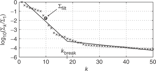
are the columns of the matrices U and V. The singular values are indexed in descending order, whereby the low-index (large) SVs mediate the coarse information from the measurement data while the high-index (small) SVs mediate the detailed information. However, the small SVs will also magnify errors, due to the numerical truncation, the machine precision and errors in the measurement data, whereby a truncation or a filtering procedure must be applied to remove or suppress the impact from the small SVs. This issue is of fundamental importance for the reconstruction: too few SVs will give an unacceptable loss of resolution while too many will give a reconstruction corrupted by the errors in the data. By a visual inspection of the plot of the function
, a trained person can determine roughly how many SVs are needed, but for a stand-alone reconstruction algorithm this procedure must be automatised.
Two common techniques for automatically determining the truncation or filtering of a SVD are the generalized cross validation (GCV) method and the L-curve method, see e.g. Citation18–20. Different versions of both these methods were tested, but none of them seems to perform well for the present problem. The theoretical foundation for GCV is that only the right-hand-side () in (61) is affected by (normally distributed) noise Citation20, but here the Hessian in the left-hand-side of (61) is affected by noise as well. Hence, the influence on the linear system (61) from noise and measurement errors differs from the cases considered in the above cited articles, wherefore it is not obvious that these regularisation methods can be used without any modifications.
Instead, we have developed a heuristic method that, despite its lack of theoretical foundation, works quite well for the present problem. The essentials about the method are outlined below:
| lowerroman | Due to the finite dimensional approximation, we do not put any confidence in the upper half of the singular values: | ||||
| lowerroman | Plotting | ||||
| lowerroman | With the above division, the singular values | ||||
4. Reconstructions using reflection data
In this section, we present results on reconstructions from synthetic as well as measured reflection data. The reflection coefficient at the connection between the feeding cable and the estimation region is defined as
Let
denote the measured reflection coefficient. If we set U+(0) = 1 in the forward solver, it follows that U−(0) becomes the calculated reflection coefficient. In the measurement operator (20), we thus use
(63)
With
in (26), the (in this case scalar) residual becomes
(64)
With the residual (65) and the measurement function (64) it is straight forward to evaluate the gradient and the Hessian from the expressions (38) and (52). Detailed expressions for the case when p = {L,C,R,G}, i.e. the usual transmission line parameters, are given in Citation15.
To avoid the inverse crime, synthetic reflection data is generated by a different numerical solver Citation2, based on the Riccati equation for the reflection coefficient instead of the linear system (5), and with a fine mesh having Nx = 500. When evaluating the reconstruction algorithm against noise contaminated data, random complex-valued noise is added to the calculated reflection coefficient. The magnitude of the noise is generated from a Gaussian distribution with zero mean and SD σ = 0.05. The argument is generated from a uniform distribution in the range 0 to 2π.
4.1. Reconstruction of volume fraction in a dielectric mixture
First, we test the method for reconstructing a single parameter. We consider a normalised problem where the estimation region has the length l = 1, and the parameters
As a model for a capacitance that depends on another parameter, we assume that the dielectric medium between the conductors is a two-phase mixture between a homogeneous host-medium and a guest-medium in terms of small spherical inclusions, which have twice the permittivity of the host-medium. Let β = β(x) (0 ≤ β ≤ 1) denote the position-dependent volume fraction of the guest-medium. It is assumed that C(β = 0) = 1, i.e. if only the host-medium is present. Using the Maxwell–Garnett mixing rule, see section 3.1 in Citation21, we obtain the following model for the shunt-capacitance:
(65)
The inverse problem is to reconstruct the volume fraction β(x) in the estimation region 0 < x < 1. Hence, in this single parameter problem p = β is the parameter to reconstruct.Footnote2
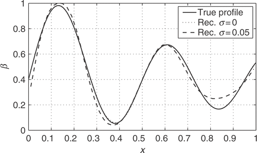
As the first case, we chose the smooth profile β(x) = 0.4 + J1(14x) (Jn denotes the n-th order Bessel function). The mesh-size is set to Nx = 50, and synthetic reflection data are generated at the frequencies f = {0.02,0.04,…,1.98,2.00}. For the regularisation, we set the tuning parameter to λ = 0.7 (cf subsection 3.5). The (constant) initial guess of β is set to its mean value ≈0.46. To assure convergence, to save computation time, and to reduce the need of computer memory, we do the reconstruction in several steps using data from different frequency intervals. The following intervals are used in sequence: f∈{[0.02,0.5],[0.02,1],[1,2],[0.02,1], with five iterations at each interval.
The results from the reconstructions (with and without noise) are depicted in . On the scale of the figure the reconstruction using noise-free data is almost indistinguishable from the true profile, although the data suffers from numerical errors due to the non-commitment of the inverse crime. The reconstruction from noisy data, on the other, exhibit clear deviations.
As the second case, we chose the following discontinuous profile:
where
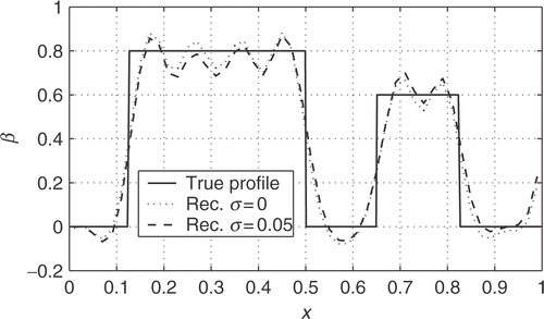
is the Heaviside step function. We keep Nx = 50 and λ = 0.7, but the overall frequency range is enlarged to f = {0.02,0.04,…,3.98,4.00}. The initial guess is set to 0.405 and we use five iterations at each of the intervals
The results from the reconstructions are depicted in . The difference between the results using noise-free and noisy data is not so remarkable as in the previous case, since in this case the reconstruction of the discontinuities requires very wide-banded data, whereby the errors are mainly due to the limited frequency range.
4.2. Simultaneous reconstruction of shunt-conductance and shunt-capacitance
Next, we consider the simultaneous reconstruction of two parameters. We consider a normalised problem where
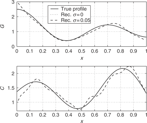
and where the parameters to be reconstructed are the shunt-conductance and shunt-capacitance, with the explicit profiles
In earlier work Citation13, it has been experienced that the frequency-domain reconstruction of two transmission line parameters is unstable if one only uses one-sided reflection data. Hence, we only consider the case when double-sided reflection data is used. Practically this means that the measurement is repeated after the transmission line has been taken out from the measurement device and reinserted in the opposite direction.
The settings in the reconstruction algorithm are the same as in the smooth single parameter case: Nx = 50,λ = 0.7 and with five iterations at the intervals
The initial guesses are set to the mean values: Ginit = 1.16,Cinit = 1.49.
The results from the reconstructions are depicted in . On the scale of the figure the reconstructions using noise-free data are very close to the true profiles, while the reconstructions from noisy data clearly exhibit deviations.
4.3. Reconstruction of shunt-capacitance from measurement data
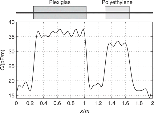
Finally, we test the reconstruction algorithm on measured data. The measurements were conducted in connection with an earlier work, and for a description of the experimental setup and the calibration procedure we refer to that work Citation13. In summary, a transmission line with a non-uniform shunt-capacitance was constructed from a flat band-cable with a length l = 2.00 m. In the region 0.250 m <x< 1.025 m the cable was sandwiched between two blocks of Plexiglas, and in the region 1.300 m <x< 1.658 m the cable was sandwiched between two blocks of polyethylene; see the top of in below. The series-inductance was estimated to L = 756 nH m− 1 and the losses where assumed to be negligible, i.e. R = G = 0.
For the reconstruction, we use reflection data from 159 frequencies in the range 45 MHz to 799.45 MHz in steps of 4.775 MHz. Since the highest frequency likely corresponds to a rather short wave-length, we use a finer mesh with Nx = 100. To avoid corrupted reconstructions, we must in this case use a lower value λ = 0.55 for the tuning parameter in the regularisation. The constant initial guess for the shunt-capacitance is set to 30 pF m− 1, and the frequency intervals used in the reconstruction are
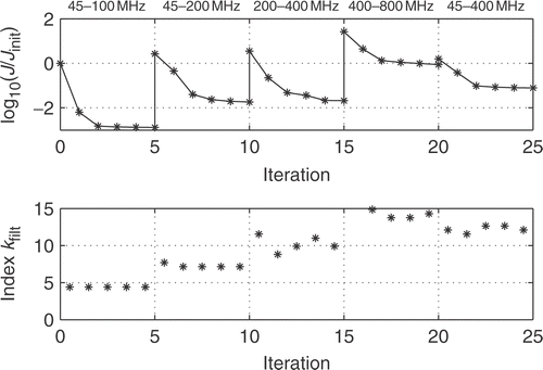
with five iterations for each interval. The development of the cost-functional as well as the index of the filtering threshold used in the SVD are depicted in . The result of the reconstruction is depicted in . From our prior knowledge that C(x) is piecewise constant, the reconstruction is quite successful, with the boundaries between the different regions located correctly.
5. Discussion and conclusions
The full Newton method for the inverse transmission line problem has been implemented and tested on artificial as well as measured reflection data. Explicit expressions for the first (gradient) and second (Hessian) orders derivatives of the cost-functional have been derived in terms of the solutions to the forward problem and the corresponding adjoint problem. Hence, these results are formally independent of the method used in the numerical implementation.
A key problem is the ill-conditioned Hessian matrix. In this work, we have used a zeroth-order Tikhonov regularisation by means of a filtered singular value decomposition, with a heuristically determined filter parameter. Although this approach works quite well, it is desired to find a more theoretically based procedure for fixing the regularisation parameter, likely some modified version of generalised cross validation Citation19 or the L-curve method Citation20.
It is obvious that the additional calculation of the Hessian makes the full Newton method computationally slower than a gradient method. However, (quite expectedly) we observed that also in our application the full Newton method has a faster convergence (in terms of the number of iterations) than the conjugate gradient method, even though this may not compensate for the extended computation time. Since we have not spent so much effort on optimising our computer code, we refrain from giving further statements about the computational efficiency. Also, in this article we have used the standard “textbook” version of Newton's method, but with the explicit Hessian available (at a moderate computational cost) it is now possible to consider other optimisation methods based on complete second-order derivatives.
Notes
1In the subsequent analysis, several x-coordinates will be needed. The subscript “m” is used for points in the measurement region.
2In this case, we can instead use p = C and compute β from C. However, p = C yields vanishing second-order derivatives in (49), whereby the singular part of the Hessian vanishes. For the purpose of investigation we instead use p = β, which yields non-vanishing contributions from both terms in (49).
3In fact, the surface integral vanishes for all surfaces enclosing the sources to F. and f., which can be shown subsequently by applying the derivation of (B.10) to a source-free region (where F. =
af. = 0) between a finite closed surface and the surface at infinity.
References
- Lundstedt, J, 1995. "A time-domain wave-splitting approach to signal restoration, internal source and parameter reconstruction". In: PhD thesis. Sweden: Royal Institute of Technology; 1995.
- Norgren, M, and He, S, 1996. An optimisation approach to the frequency-domain inverse problem for a non-uniform LCRG transmission line, IEEE Transactions on Microwave Theory and Techniques 44 (1996), pp. 1503–1507.
- Grootveld, CJ, Segal, A, and Scarlett, B, 1998. Regularized modified newton-rahpson technique applied to electrical impedance tomography, International Journal of Imaging Systems and Technology 9 (1998), pp. 60–65.
- Pastorino, M, Massa, A, and Caorsi, S, 2000. Microwave inverse scattering technique for image reconstruction based on a genetic algorithm, IEEE Transactions on Instrumentation and Measurement 49 (2000), pp. 573–578.
- Harada, H, Tanaka, M, and Takenaka, T, 2001. Image reconstruction of a three-dimensional dielectric object using a gradient-based optimisation, Microwave and Optical Technology Letters 29 (2001), pp. 332–336.
- Zhou, H, Takenaka, T, and Tanaka, T, 2005. Time-domain reconstruction of lossy object using dipole antennas, Microwave and Optical Technology Letters 44 (2005), pp. 238–243.
- Yang, Y, Hallerod, T, Ericsson, D, Hellervik, A, Bondeson, A, and Rylander, T, 2005. Gradient optimisation of microwave devices using continuum design sensitivities from the adjoint problem, IEEE Transactions on Magnetics 41 (2005), pp. 1780–1783.
- Norgren, M, 2006. On the problem with intermodal dispersion when using multiconductor transmission lines as distributed sensors, Progress in Electromagnetics Research 56 (2006), pp. 129–150.
- Gustafsson, M, and He, S, 2000. An optimisation approach to two-dimensional time domain electromagnetic inverse problems, Radio Science 35 (2000), pp. 525–536.
- Takenaka, T, Jia, H, and Tanaka, T, 2001. Microwave imaging of an anisotropic cylindrical object by a forward-backward time-stepping method, IEICE Transactions on Electronics E84-C (2001), pp. 1910–1916.
- Klose, AD, and Hielscher, AH, 2003. Quasi-Newton methods in optical tomography image reconstruction, Inverse Problems 19 (2003), pp. 387–409.
- Franchois, A, and Tijhuis, AG, 2003. An quasi-newton reconstruction algorithm for a complex microwave imaging scanner environment, Radio Science 38 (2003), p. VIC, 12..
- Norgren, M, 2005. Chebyshev collocation and Newton-type optimisation methods for the inverse problem on non-uniform transmission lines, IEEE Transactions on Microwave Theory and Techniques 53 (2005), pp. 1561–1568.
- Lundstedt, J, and Norgren, M, 2003. Comparison between frequency domain and time domain methods for parameter reconstruction on non-uniform dispersive transmission lines, Journal of Electromagnetic Waves and Applications 17 (2003), pp. 1735–1737.
- Norgren, M, and Takenaka, T, 2006. "Full Newton method for inverse transmission line problems, utilising explicit second order derivatives". In: Technical Report, Div. Sweden: Electromagnetic Engineering, Royal Institute of Technology; 2006.
- Kreyszig, E, 1978. Introductory Functional Analysis with Applications. New York: Wiley & Sons; 1978.
- Debnath, L, and Mikusiński, P, 1990. Introduction to Hilbert Spaces with Applications. New York: Academic Press; 1990.
- Rodriguez, G, Seatzu, S, and Theis, D, 2003. A new technique for ill-conditioned linear systems, Numerical Algorithms 33 (2003), pp. 433–442.
- Golub, GH, Heath, M, and Wahba, G, 1979. Generalized cross-validation as a method for choosing a good ridge parameter, Technometrics 21 (1979), pp. 215–223.
- Hansen, PC, and O'Leary, DP, 1993. The use of the L-curve in the regularization of discrete ill-posed problems, SIAM: Journal on Scientific Computing 14 (1993), pp. 1487–1503.
- Sihvola, A, 1999. Electromagnetic Mixing Formulas and Applications. London: IEE Electromagnetic Wave Series; 1999.
Appendix
Consider the quadratic form
(66)
Since the indices i., j and the variables
are “dummys”, which disappear during the summation and integration procedures, one obtains
(67)
which proves that only the symmetric part
(68)
contributes to the result.
Appendix
Here, we give the generalisation of the present method to the case of a three-dimensional scatterer of a linear, heterogeneous and dispersive bianisotropic material, described by the general frequency-domain constitutive relations
(69)
(70)
where
and
are the permittivity and permeability tensors, respectively, and
and
are the magnetoelectric cross-coupling tensors. The complex valued constitutive parameters are assumed to depend on a set
of real-valued fundamental parameters. The scatterer is confined to an estimation region
, with a finite extent. It is assumed that
belongs to the Hilbert space
of Np-compnent functions, for which each component is in the space
. The region outside
is filled with an isotropic, homogeneous and non-dispersive medium, which can be assumed to be vacuum.
The scatterer is illuminated by the fields from a primary source current density J., located outside . It is assumed that the primary source is of finite extent and located at a finite distance from the scatterer, i.e. we do not consider plane wave incidence. The electric and magnetic fields are measured in the region outside
, and the inverse problem is to reconstruct a subset of p using the acquired measurement data. The subset of unknown parameters may be increased if more information is added, by varying the angular frequency ω as well as the location of the primary source J..
B.1. The Maxwell operator and the adjoint problem
The dynamics of the fields obey the time-harmonic Maxwell's equations:
(71)
(72)
Since both the primary source region and the scattering region are of finite extent, the fields have the asymptotic behaviours
(73)
and satisfy the following outgoing wave (radiation) conditions as r→∞:
(74)
(75)
where
and
are the wave impedance and wave number in vacuum, respectively. O(τn) means that O(τn) / τn is bounded as τ→0 and o(τn) means that o(τn) / τn→0 as τ→0.
Maxwell's equations (B.3) and (B.4) and the constitutive relations (B.1) and (B.2) yield the following equation system:
(76)
which together with the outgoing wave conditions determine the solution to the scattering problem. We introduce the six-vectors
for the fields and the primary source, and the 6 × 6 matrix
Furthermore, we define the matrix differential operator
referred to as the Maxwell operator, whereby (B.8) is written compactly as
(77)
The inner product between two vector or matrix fields a.(r.) and b.(r.) over any region in the three-dimensional space is defined as
Introduce a pair of adjoint fields e. and h.. Let
be a large spherical volume, with radius r, which contains the primary source and the scatterer. The surface of
is denoted
. Consider integration by parts of the following inner-product integral over
[cf (B.8)]:
(78)
Introduce the adjoint field six-vector
and the adjoint Maxwell operator
where
In a compact notation (B.10) thus becomes
(79)
To make (B.11) a proper adjoint relation, we must make the surface integral to vanish. It is anticipated that the adjoint fields have localised sources, whereby
(80)
In addition, e. and h. have to satisfy the following incoming wave conditions as r→∞:
(81)
(82)
Using (B.6), (B.13), (B.5) and (B.12), the surface integral becomes
Letting
, the surface integral vanishesFootnote3 whereby we obtain the adjoint relation for the Maxwell operator
:
(83)
The fundamental solution for the adjoint field is a 6 × 6 matrix adjoint Green's function:
which is determined from the differential equation
and where the 3 × 3 submatrices satisfy the incoming wave conditions
B.2. The gradient, the Hessian and the Newton step
For the bianisotropic inverse scattering problem, the residual when comparing the calculated field F. with the measurements m. becomes (cf subsection 3.1)
Now, the gradient and the Hessian can be determined merely by replacing
,
, dx→dv, etc. in the subsections 3.2 and 3.3, respectively. Hence, the gradient becomes
(84)
while the Hessian becomes
where
(85)
(86)
The integral equation for the Newton step becomes
(87)

