Abstract
This work deals with the use of the conjugate gradient method with adjoint problem for the estimation of an unknown source term in a two-region problem. The physical problem consists of heat conduction in two contacting rectangular regions, where the source term is known to exist in only one of them. The source term is supposed to vary in time as well as within the region. Results are presented for the inverse identification problem by using simulated temperature measurements containing random errors. In addition, results are presented for an inverse design problem with application in hot embossing microreplication microfabrication technology employed for the fabrication of polymer-based Micro-electromechanical Systems (MEMS).
1. Introduction
Inverse problems dealing with the identification of source terms have been drawing the attention of different research groups for more than a decade, because of its importance in many practical applications, such as predicting and controlling chemical reactions and phase-change, detecting inclusions or non-homogeneities, etc. For the solution of this kind of inverse problem, a variety of methods have been examined Citation1–20.
This study is concerned with the estimation of the source term in a two-region heat conduction problem. The physical problem of interest is typical of the manufacturing of Micro-electromechanical Systems (MEMS) and is called Hot Embossing Microfabrication Microreplication (HEMM). Such technique consists of pressing a mold on a substrate under a prescribed thermal history and can also be used for the fabrication of micro- and macro-scale polymer parts. In general, the polymer substrate and the mold are heated to a temperature just above the polymer glass transition temperature. At this temperature, the polymer undergoes significant variations in its physical properties, notably in the Young's modulus, and changes from hard and brittle to soft and pliable. The mold is then pressed on the polymer until features get replicated and then both the mold and the substrate are cooled down to a temperature below the glass transition temperature for de-embossing Citation21.
The estimation of the source term within the mold by using the temperature variation at selected points within the substrate is under observation in this article. Such an inverse problem can be aimed at the identification of the unknown source term by using temperature measurements within the substrate, or, alternatively, at the design of the source term that will result in a prescribed temperature history required for the HEMM technique. Results are presented for both the identification and the design types of inverse problems. For the estimation of the source term, no information is a priori assumed available regarding its functional form, except for the functional space that it belongs to. It is assumed that the unknown belongs to the Hilbert space of square integrable functions in the spatial and time domains of interest. The unknown source term is estimated by using the conjugate gradient method with adjoint problem formulation Citation22–24, as described below.
2. Physical problem and mathematical formulation
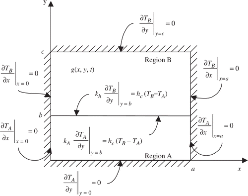
The physical problem considered in this work consists of the two-dimensional heat conduction in two contacting rectangular regions, as depicted in . The widths of both regions are a, while the thickness of region A is b and the thickness of region B is (c − b). Regions A and B are supposed to initially be at the uniform temperatures T0A and T0B, respectively. For t > 0, the two regions are put in contact and heat is generated in region B at a volumetric rate g(x,y,t). The contact conductance at the interface between the two regions, hc, is supposed to be uniform and the other boundaries of regions A and B are supposed to be insulated. By assuming that the thermal properties of regions A and B are constant, the mathematical formulation for this problem is given in dimensionless form as:
Region A
(1)
(2)
(3)
(4)
(5)
(6)
Region B
(7)
(8)
(9)
(10)
(11)
(12)
In order to write equations (1a–f) and (2a–f), the following dimensionless groups were defined:
(13)
(14)
where k is the thermal conductivity, α is the thermal diffusivity, and the subscripts A and B refer to regions A and B, respectively.
3. Direct problem and inverse problem
The problem defined by equations (1a–f) and (2a–f), with known initial and boundary conditions, contact conductance, thermophysical properties and source term constitutes a direct problem that is concerned with the determination of the transient temperature fields θA(X,Y,τ) and θB(X,Y,τ).
For the inverse problem of interest here, the source term G(X,Y,τ) is regarded as unknown, while the other quantities appearing in the formulation of the direct problem are considered to be known with a high degree of accuracy. For the solution of the inverse problem, we consider available the transient temperature histories μAm(τ) at positions (Xm,Ym), m = 1, … , M, in region A, as well as μBn(τ), n = 1, … , N, at positions (Xn,Yn) in region B. For the design inverse problem, μAm(τ) and μBn(τ) represent desired temperatures for the fabrication procedure, while for the identification inverse problem, μAm(τ) and μBn(τ) represent temperature measurements. The measurements contain errors, which are supposed to be additive, uncorrelated, normally distributed, with known and constant standard deviation and zero mean.
For the estimation of the unknown function G(X,Y,τ), we make no a priori assumption regarding its functional form, except that it belongs to the Hilbert space of square-integrable functions Citation22–24 in the domain 0 < X < 1, B < Y < C and 0 < τ< τf, where τf is the duration of the time interval of concern for the inverse analysis. For the solution of the present inverse problem, we consider the minimization of the following functional:
(15)
The minimization of the objective functional (4) is performed by the conjugate gradient method with adjoint problem formulation Citation22–24. The iterative procedure of such a method is presented below.
4. Conjugate gradient method
The iterative procedure of the conjugate gradient method, as applied to the estimation of the function G(X,Y,τ), is given by:
(16)
where the superscript k denotes the number of iterations and βk is the search step size. The direction of descent, d k, is obtained as a linear combination of the gradient direction at iteration k with directions of descent at previous iterations. It is given as Citation22–24:
(17)
Different expressions are available in the literature for the conjugation coefficient, γk. In this work, we use the so-called Fletcher–Reeves version of the conjugate gradient method, where the conjugation coefficient is written as Citation22–24:
(18)
For the implementation of the iterative procedure of the conjugate gradient method given by equations (5a–c), expressions are required for the gradient direction ∇ S [G k (X, Y, τ)], as well as for the search step size βk. Two auxiliary problems are used to derive these expressions, namely the sensitivity and adjoint problems, as described next.
5. Sensitivity problem and search step size
The sensitivity problem is used to determine the variations ΔθA(X,Y,τ) and ΔθB(X,Y,τ) that the temperatures θA(X,Y,τ) and θB(X,Y,τ) undergo, respectively, when the unknown function is perturbed by ΔG(X,Y,τ) Citation22–24. The sensitivity problem is derived by substituting into the direct problem given by equations (1a–f) and (2a–f), θA(X,Y,τ) by [θA(X,Y,τ) + ΔθA(X,Y,τ)], θB(X,Y,τ) by [θB(X,Y,τ) + ΔθB(X,Y,τ)] and G(X,Y,τ) by [G(X,Y,τ) + ΔG(X,Y,τ)]. The original direct problem is then subtracted from the resulting equations in order to obtain the following sensitivity problem:
Region A
(19)
(20)
(21)
(22)
(23)
(24)
Region B
(25)
(26)
(27)
(28)
(29)
(30)
The search step size is obtained by minimizing the objective functional with respect to βk at each iteration Citation22–24. The following expression results:
(31)
where ΔθA(X,Y,τ,d k) and ΔθB(X,Y,τ,d k) are the solutions of the sensitivity problem given by equations (6a–f) and (7a–f), obtained by setting ΔG(X,Y,τ) = d k(X,Y,τ).
6. Adjoint problem and gradient equation
The adjoint problem is derived by multiplying the governing equations of the direct problem, equations (1a) and (2a), by the Lagrange multipliers λA(X,Y,τ) and λB(X,Y,τ), respectively. The equations are then integrated in the spatial and time domains that they are valid and added to the original functional (4). The directional derivative of the extended functional in the direction of the perturbation of the unknown function is then obtained and the resultant expression, after some lengthy but straightforward manipulations, is allowed to go to zero Citation22–24. The following adjoint problem for the determination of the Lagrange multipliers λA(X,Y,τ) and λB(X,Y,τ) results:
Region A
(32)
(33)
(34)
(35)
(36)
(37)
Region B
(38)
(39)
(40)
(41)
(42)
(43)
By applying the limiting process used to obtain the adjoint problem, the directional derivative of the objective functional along the direction of the perturbation ΔG(X,Y,τ) reduces to:
(44)
We now invoke the hypothesis that the unknown function belongs to the Hilbert space of square integrable functions in the domain 0 < X < 1, B < Y < C, and 0 < τ < τf, so that we can write such directional derivative as:
(45)
Therefore, by comparing equations (11a) and (11b) we obtain the gradient direction as:
(46)
After developing the expressions for the search step size and for the gradient direction, the iterative procedure of the conjugate gradient method given by equations (5a–c) can be applied until a suitable convergence criterion is satisfied. In this article, the iterative procedure was stopped when the objective functional given by equation (4) became sufficiently small. The discrepancy principle Citation22–24 was used to specify the tolerance for the stopping criterion when simulated temperature measurements were used for the inverse analysis of source term identification. For the inverse design problem, the tolerance was specified as a small number.
7. Results and discussions
7.1. Identification problem
Let us consider first, the solution of the inverse problem for the identification of the source term function G(X,Y,τ) by using simulated temperature measurements containing random errors. For the results presented below, the dimensions of regions A and B were taken as a = 0.3 m, b = 0.015 m, and (b − c) = 0.1 m, so that B = 0.05 and C = 0.38. In order to examine strict cases involving materials with thermal conductivity and thermal diffusivity of different orders of magnitudes, we assumed regions A and B to be made of Teflon and steel, respectively, with the following thermophysical properties: kA = 0.23 Wm−1 K−1, αA = 1.005 × 10⁻⁷ m2s −1, kB = 45 Wm−1 K−1 and αB = 1.240 × 10⁻⁵ m2s−1, that is, K = 195.65 and Λ = 123.35. Both regions A and B were supposed to initially be at the same temperature T0A = T0B = 27°C and in perfect thermal contact. The duration of the experiment was taken as 2340 s, with a measurement frequency of 1.1 Hz. In dimensionless terms, the duration of the experiment was τf = 2.613 × 10⁻³. However, in order to overcome the difficulties encountered in the inverse problem solution in the neighborhood of the final time, which result from the null gradient at τ = τf, see equations (9f), (10f) and (12), the results are presented below up to τ = 2 × 10⁻³. The sensors were supposed to be located only within region A, which constitutes a difficult situation for the estimation of the source term in region B. For the cases examined below, the sensors were evenly distributed at the vertical position Y = 0.03, which corresponds to 0.006 m below the interface between regions A and B. The simulated measurements contained random errors with standard deviation of 0.003, which is equivalent to 1°C. Such simulated measurements were generated by using functions containing discontinuities and sharp-corners for the source term. These functions were supposed to vary from zero to a maximum value of 106 Wm−3. The initial guess for the iterative procedure of the conjugate gradient method was taken as a null source term.
The direct, sensitivity, and adjoint problems were solved numerically by using the finite-volume method. Regions A and B were discretized with 30 volumes along the X direction and 25 and 50 volumes along their thickness, respectively. A step of Δτ = 10−6 was used to march the solution in time. Such numbers of volumes and time step were selected though a grid convergence analysis and by comparing the numerical and analytical solutions for the direct problem.
For the test-cases examined below in the inverse identification problem, the source-function was assumed to be separable in the form:
(47)
summarizes the test-cases examined for the inverse identification problem. Test-cases 1–3 deal with the identification of a spatially uniform function that only varies in time. These test-cases differ by the number of sensors used in the inverse analysis. For test-case 4, the unknown function is uniform along the Y direction and constant in time, thus varying only along the longitudinal X direction. Test-case 5 involves a function that varies in time and along the longitudinal X direction, but is uniform along the Y direction.
Table 1. Test-cases examined for the identification inverse problem
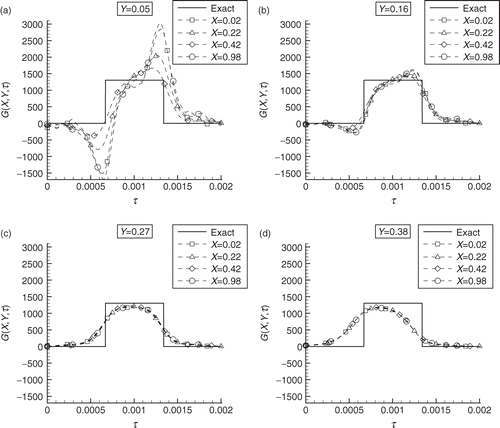
presents the results for test-case 1, involving the estimation of the time variation of a spatially uniform source term, obtained by using five sensors. present the results obtained for the positions Y = 0.05, 0.16, 0.27, and 0.38, respectively, and for each of these figures the results for X = 0.02, 0.22, 0.42, and 0.98 are given. We notice in that the accuracies of the estimated functions deteriorate for vertical positions closer to the interface at Y = 0.05, or closer to the upper boundary at Y = 0.38. On the other hand, the estimated functions are affected very little by the longitudinal position X, except for Y = 0.05. At Y = 0.05, the estimated functions are less accurate in regions near the surfaces at X = 0 and X = 1. It is interesting to notice in that the differences between estimated and exact functions, in the regions where the exact function is underestimated, are practically identical to those differences in the regions where the exact function is overestimated. Therefore, the total energy input is accurately estimated, despite the fact that the source term functional form is not exactly recovered for some cases.
Figure 2. Test-case 1–inverse problem solution obtained with five sensors for a uniform exact function containing discontinuities in time: (a) Y = 0.05, (b) Y = 0.16, (c) Y = 0.27, and (d) Y = 0.38.
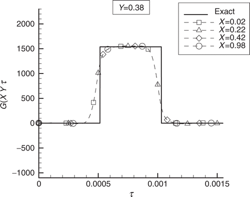
presents the results obtained for test-case 2, involving the same exact function of , but the measurements of 10 sensors instead of 5. A comparison of and shows that, as expected, the solution improves as the measurements of more sensors are used, since more information is available for the inverse analysis. Ideally, if a large number of sensors could be used, including sensors in the mold, the agreement between the exact and the estimated functions would be excellent even for regions distant from the interface, as illustrated in (test-case 3). This figure shows the results for Y = 0.38, obtained with one sensor in each control-volume in the substrate and one sensor in two-thirds of the control-volumes of the mold.
Figure 3. Test-case 2–inverse problem solution obtained with 10 sensors for a uniform exact function containing discontinuities in time: (a) Y = 0.05, (b) Y = 0.16, (c) Y = 0.27, and (d) Y = 0.38.
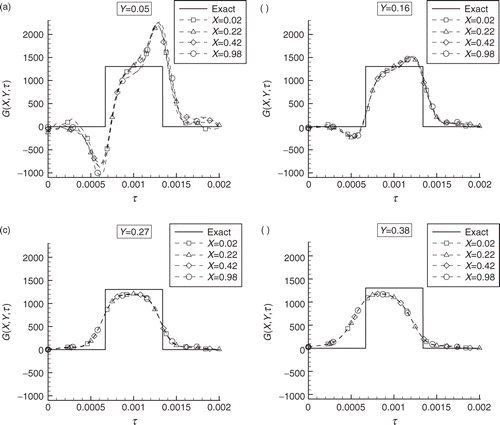
Figure 4. Test-case 3–inverse problem solution at Y = 0.38, obtained with 1740 sensors for a uniform exact function containing discontinuities in time.
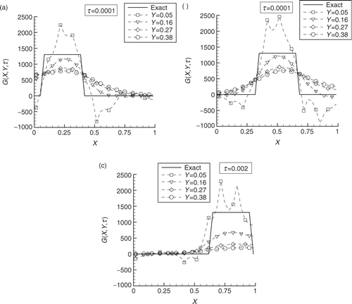
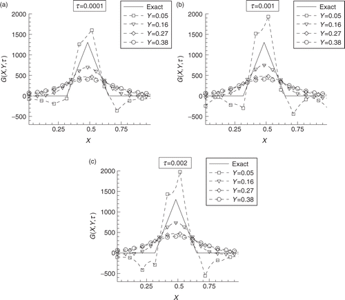
We now examine a test case involving the identification of a source term that varies along the X direction, but is constant in time and uniform along the Y direction. presents the results obtained for test-case 4, involving the estimation of a source term containing sharp corners for τ = 0.0001, τ = 0.001, and τ = 0.002, respectively, obtained by using 10 sensors in the inverse analysis. In each of these figures, the results for Y = 0.05, 0.16, 0.27, and 0.38 are given. These figures show that the accuracy of the inverse problem solution deteriorates for the positions located farther from the interface, because the measurements are less affected by the source term in such locations. However, as for the results shown in , the total energy input was accurately estimated. The inverse problem solution was not affected by the time variable in this case, even for τ = 0.002, which is near the final time considered for the problem.
Figure 5. Test-case 4–inverse problem solution obtained with 10 sensors for an exact function varying along the longitudinal direction: (a) τ = 0.0001, (b) τ = 0.001, and (c) τ = 0.002.
The results for test-case 5, dealing with a source term that varies in time and along the longitudinal X direction, but is uniform along the Y direction, are presented in for τ = 0.0001, τ = 0.001 and τ = 0.002, respectively. Such results were obtained with the measurements of 10 sensors. As for the case involving only the variation of the source term along the X direction (, we notice in that the results for vertical positions close to the interface are more accurate. Furthermore, the results for this case become less accurate as the final time is approached (, for τ = 0.002), when the estimated function is affected by the null gradient. We also examined test-cases involving the identification of source terms varying along the vertical Y direction. However, the exact function could not be recovered unless measurements were considered available within region B as well, which was an expected result from the analysis of Savateev Citation25 regarding the solvability of an inverse identification problem similar to the present one.
7.2. Design problem
We now consider the inverse problem of designing the heat source term in the mold so that the temperature at the mold/substrate interface follows a desired history imposed by the manufacturing process. Based on data of reference Citation21, we assumed the substrate and the mold to have the following properties: kA = 0.19 Wm−1 K −1, αA = 1.144 × 10⁻⁷ m2 s−1, kB = 14.8 W m K −1 and αB = 9.056 × 10⁻⁶ m2 s−1, that is, K = 77.89 and Λ = 79.16. Both regions A and B were supposed to be initially at the same temperature T0A = T0B = 27°C. The mold and substrate dimensions () were supposed to be a = 0.075 m, b = 0.001 m, and (b − c) = 0.065 m and the duration of the hot embossing process was taken as 1400 s, that is, B = 0.013, C = 1, and τf = 0.028. The regions were discretized with the same number of volumes used for the inverse identification problem examined above, but the time increment was taken as Δτ = 10−5. Uniform interface temperature and perfect contact between regions A and B were assumed for the results presented hereafter.
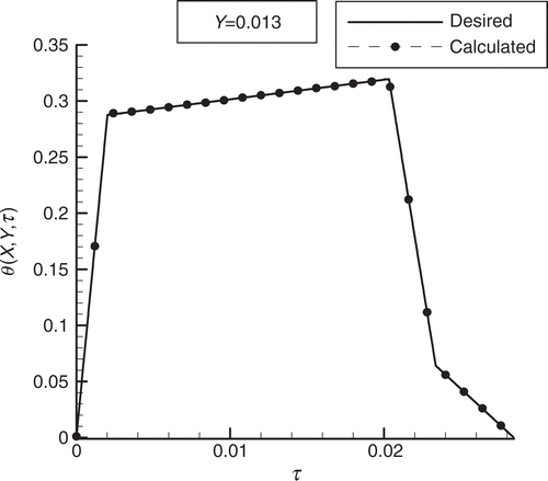
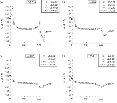
presents the desired temperature variation at the interface between regions A and B, as well the calculated temperatures obtained with the heat source term that resulted from the solution of the present inverse design problem. The agreement between desired and calculated temperatures is perfect within the graph scale, despite the fact that the desired temperature variation contains sharp corners. presents the resultant heat source term at positions Y = 0.013, 0.34, 0.67, and 1.0, respectively. Each of these figures shows the results for X = 0.02, 0.22, 0.42, and 0.98. We note in that the source term resultant from the design procedure does not vary along the X direction for such test case. In addition, periods of heating (positive source) and cooling (negative source) can be clearly identified, as required for the sharp increase and decrease in temperature at times τ = 0 and τ = 0.02, respectively (). The obtained results reveal that the conjugate gradient method of function estimation is capable of providing smooth and stable solutions for the source term. The magnitude of the source term decreases for positions farther from the interface. This is due to the low sensitivity of the interface temperature with respect to the source term at these locations, similarly to the inverse identification problem examined above. We note that the present inverse design analysis assumes that the source term is continuous within mold; but for practical implementation, discrete heat sources and cooling channels will be required. The results obtained with the conjugate gradient method of function estimation permit the selection of the number and position of the heat sources and cooling channels, as well as the heating power, cooling fluid temperature, and convective heat transfer coefficient, which will result in the desired interface temperature variation.
8. Conclusions
This work dealt with the solution of the inverse problem of estimating the source term function in a rectangular region, by using as input data the temperature history at points in another contacting region. The conjugate gradient method of function estimation was applied for the solution of the inverse problem. Several test cases were examined in the study, including the identification of functions varying only in time, only in space and varying simultaneously in space and time, by using simulated temperature measurements in the inverse analysis. In addition, results were also presented for the design of the source term for a prescribed interface temperature required for a manufacturing process.
Generally, for the inverse identification problem the agreement between estimated and exact functions improves for those locations closer to the interface between the two regions. For the inverse design problem, the conjugate gradient method is capable of recovering smooth functions that result in perfect agreement between desired and calculated interface temperatures.
Nomenclature
| a,b,c | = | Dimensions of the rectangular region |
| d | = | Direction of descent |
| G(X,Y,τ) | = | Dimensionless source term |
| S | = | Objective functional |
| X,Y | = | Dimensionless Cartesian coordinates |
Greeks
| Δθ(X,Y,τ) | = | Sensitivity function, solution of the sensitivity problem given by equations (6) and (7) |
| β | = | Search step size |
| γ | = | Conjugation coefficient |
| λ(X,Y,τ) | = | Lagrange multiplier, solution of the adjoint problem given by equations (9) and (10) |
| μ(τ) | = | Measured or desired temperature |
| θ(X,Y,τ) | = | Dimensionless calculated temperature, solution of the direct problem given by equations (1) and (2) |
| τ | = | Dimensionless time |
| τf | = | Dimensionless final time |
Subscripts
| A,B | = | Regions A and B, respectively |
Superscripts
| k | = | Number of iterations |
Acknowledgments
The Brazilian authors are thankful for the support provided by CNPq and FAPERJ, agencies for the fostering of science from the Brazilian and State of Rio de Janeiro governments, respectively. H. R. B. O and M. J. C are thankful to the hospitality of Prof. G. Dulikravich and of the Mechanical & Aerospace Engineering Department during their visits to UT-Arlington.
References
- Huang, CH, and Ozisik, MN, 1992. Inverse problem of determining the unknown strength of an internal plane heat source, Journal of Franklin Institute 329 (4) (1992), pp. 751–764.
- Silva Neto, AJ, and Ozisik, MN, 1992. Two-dimensional inverse heat conduction problem of estimating the time-varying strength of a line source, Journal of Applied Physics 71 (11) (1992), pp. 5357–5362.
- Silva Neto, AJ, and Ozisik, MN, 1994. The estimation of space and time dependent strength of volumetric heat source in a one-dimensional plate, International Journal of Heat and Mass Transfer 37 (6) (1994), pp. 909–915.
- Orlande, HRB, and Özisik, MN, 1994. Determination of the reaction function in a reaction-diffusion parabolic problem, ASME Journal of Heat Transfer 116 (1994), pp. 1041–1044.
- Yang, C-Y, 1998. Solving the two-dimensional inverse heat source problem through the linear least square error method, International Journal of Heat and Mass Transfer 41 (2) (1998), pp. 393–398.
- Yang, C-Y, 1998. A sequential method to estimate the strength of the heat source based on symbolic computation, International Journal of Heat and Mass Transfer 41 (14) (1998), pp. 2245–2252.
- Le Niliot, C, and Gallet, P, 1998. Infrared thermography applied to the resolution of inverse problems: recovery of line sources and boundary conditions, Revue Generale De Thermique 37 (1998), pp. 629–643.
- Park, HM, Chung, OY, and Lee, JH, 1999. On the solution of inverse heat transfer problem using the Karhunen-Loève Galerkin method, International Journal of Heat Mass Transfer 42 (1999), pp. 127–142.
- Abou Khachfe, R, and Jarny, Y, 1999. "Estimation of heat sources within two dimensional shaped bodies". In: Keith, Woodbury, ed. Inverse Problems in Engineering: Theory and Practice. Washington: Port Ludlow; 1999. pp. 309–316, (New York:ASME).
- Le Niliot, C, and Lefevre, F, 2000. "A method for multiple point heat sources identification in a diffusive system: application to a 2D experiment". In: Paper NHTC2000-12025, 34th National Heat Transfer Conference. Pittsburgh, Pennsylvania. 2000.
- Su, J, and Silva Neto, A, 2001. Two-dimensional inverse heat conduction problem of source strength estimation in cylindrical rods, Applied Mathematical Modelling 25 (2001), pp. 861–872.
- Lefevre, F, and Le Niliot, C, 2002. Multiple transient point heat sources identification in heat diffusion: application to experimental 2D problems, International Journal of Heat and Mass Transfer 45 (2002), pp. 1951–1964.
- Kwag, D-S, Kim, W-S, and Lee, K-S, 2002. "An inverse natural convection problem in estimating the location and strength of a heat source". In: Proceedings of the 12th International Heat Transfer Conference. Vol. 4. France. 2002. pp. 885–861.
- Yi, Z, and Murio, D, 2002. "Source terms identification for the diffusion equation". In: Orlande, Helcio R.B., ed. Inverse Problems in Engineering: Theory and Practice. Vol. I. Rio de Janeiro, Brazil: e-papers; 2002. pp. 99–106.
- Fatullayev, AG, 2004. Numerical solution of inverse problem of determining an unknown source term in a two-dimensional heat equation, Applied Mathematical Computation 152 (2004), pp. 659–666.
- Rodrigues, FA, Orlande, HRB, and Dulikravich, GS, 2004. Simultaneous estimation of spatially-dependent diffusion coefficient and source-term in a nonlinear 1D diffusion problem, Mathematics and Computers in Simulation 66 (2004), pp. 409–424.
- Bellini, R, Orlande, HRB, and Blas, JG, 2004. "Estimation of source term parameters during solid-solid phase transformations of steels". In: Colaço, MJ, Orlande, HRB, and Dulikravich, GS, eds. Inverse Problems, Design and Optimization, Paper IPDO-054, Rio de Janeiro. Vol. I. Rio de Janerio: E-paper publishing House; 2004. pp. 320–327.
- Silva Neto, A, and Su, J, 1999. "The estimation of heat source strength in plate-type fuel elements with cladding". In: Woodbury, K, ed. Inverse Problems in Engineering: Theory and Practice, ASME. New York: ASME; 1999. pp. 397–402.
- Huang, C-H, and Cheng, S-C, 2001. A three-dimensional inverse problem of estimating the volumetric heat generation for a composite material, Numerical Heat Transfer Part A (2001), pp. 383–403.
- Guo, J, Le Masson, P, Artioukhine, E, and Loulou, T, 2006. Estimation of a source term in a two dimensional heat transfer problem: application to an electron beam welding, Inverse. Problems in Science and Engineering 14 (1) (2006), pp. 21–38.
- Chen, CL, and Jen, F, 2004. Fabrication of polymer splitter by micro hot embossing technique, Tamkang Journal of Science Engineering 7 (1) (2004), pp. 5–9.
- Alifanov, OM, 1994. Inverse Heat Transfer Problems. New York: Springer-Verlag; 1994.
- Alifanov, OM, Artyukhin, E, and Rumyantsev, A, 1995. Extreme Methods for Solving Ill-Posed Problems with Applications to Inverse Heat Transfer Problems. New York: Begell House; 1995.
- Özisik, MN, and Orlande, HRB, 2000. Inverse Heat Transfer: Fundamentals and Applications. New York: Taylor & Francis; 2000.
- Savateev, EG, 1995. On problems of determining the source function in a parabolic equation, Journal of Inverse Ill-Posed Problems 3 (1) (1995), pp. 83–102.
