Abstract
Thermoacoustic computed tomography provides a novel and promising technology in medical imaging. It is based on the generation of acoustic waves inside tissues by stimulation with electromagnetic waves. Acoustic waves are measured outside the stimulated sample and converted into a three-dimensional (3D) image with high contrast and high resolution. Since optical fibres can be used to guide a laser beam on an arbitrary curve, it is possible to realize an experimental buildup in such a way that the acoustic pressure is measured over circles. The aim of this article is to present the mathematical theory when the acoustic pressure is measured over a stack of circles.
1. Introduction
Thermoacoustic computed tomography (TACT) is an emerging technology for non-invasive medical imaging. Based on the excitation of high bandwidth acoustic waves with pulsed non-ionizing electromagnetic energy Citation1–4 it combines the high contrast of optical imaging with the high resolution of ultrasonic imaging.
The common approach has been to use small conventional piezoelectric transducers Citation3,Citation4 that approximate point-detectors. A point-detector measures the mean values of the absorption density function over spherical surfaces with the point-detector in their centre Citation4,Citation5. Reconstruction algorithms that are based on point-detector data yield images with a spatial resolution essentially determined by the size and bandwidth of the used piezoelectric transducers Citation6. A prerequisite for achieving a high-resolution image is therefore that the detector size in all three dimensions should not exceed the desired minimum resolution. Small detectors with high bandwidth and sensitivity are technically hardly realizable Citation7,Citation8. Different approaches have been introduced in Citation9,Citation10, where the detector size is larger (in one or two dimensions) than the resolution limit.
Line-shaped detectors Citation9,Citation11,Citation12 integrate the acoustic pressure over its length and can be implemented by a Mach–Zehnder interferometer (which is an optical device where the the thermoacoustic pressure is measured with a laser beam). One drawback of the approach with linear detectors is that the lines are not aligned to the observed object, i.e. the points on a line move away from the object. Another disadvantage is that measuring the integrated pressure over laser beams around the object does not provide a simple and compact experimental buildup.
In this article, we propose to use integrals of the pressure over a stack of parallel closed circles instead of infinite lines. Optical fibres allow it to guide laser beams along curved paths. Therefore, circular integrating detectors can be implemented by fibre-based interferometers as acoustic detector Citation13. Since it is possible to fabricate optical fibres out of materials, which have nearly the same acoustical density like the surrounding liquid in which they are contained Citation14, there are little refraction effects expected.
The outline of this article is as follows. In Section 2, we present the proposed setup for PAT with circular integrating detectors. It turns out that the three-dimensional imaging problem reduces to a sequence of two-dimensional ones (similar as in Citation12). In Section 3 we derive an analytic reconstruction formula.
2. Photoacoustic tomography with circular detectors
Photoacoustic tomography (PAT) is based on the excitation of acoustic pressure waves p(x, t) inside an object of interest, when exposed to non-ionizing electromagnetic radiation Citation1,Citation2,Citation4,Citation15. It combines the advantages of purely optical tomography (high contrast) and pure ultrasound imaging Citation16,Citation17. It has demonstrated great promise for important medical applications including cancer diagnostics Citation18–22 and imaging of vasculature Citation23–26. For recent experimental buildups of PAT scanners, the reader is referred to Citation4,Citation11.
Mathematically, the thermoacoustic pressure is described by the initial value problem (IVP)
(1)
(2)
(3)
(We assume that the speed of sound is spatially constant and equal to one.) Suppose the initial pressure f has compact support in some region Ω ⊂ ℝ3. The aim of PAT is to determine the initial pressure from the measurements p(x, t) outside Ω.
The classical approach with point-detector measurements leads to problem of reconstruction p from p(x, t), for (x, t) ∈ S × ℝ+, where S ⊂ ∂Ω. A different approach Citation9,Citation11,Citation12 investigates so-called integrating line detectors, which measure the overall pressure
(4)
on a line. This approach is motivated by the superior measuring accuracy of integrating line detectors, which can be realized by a thin laser beam that is part of a Fabry–Perot or Mach–Zehnder interferometer Citation11,Citation13. By integrating (1) over the family of lines parallel to a given direction (i.e. taking the Radon transform) one obtains a wave equation in two dimensions. In this situation, the inverse problem of recovering f decomposes to a sequence of two-dimensional (2D) problems: first, the Radon transform of f (in a given direction) is reconstructed from values of the 2D wave equation on a curve, while in the the second stage a three-dimensional image is reconstructed by inverting the Radon transform.
A drawback of integrating line detectors compared to ultrasonic transducers is that they are not aligned to the object since points on the line ‘move away’ from the object quickly. Moreover, taking measurements with laser beams around the object does not lead to a compact experimental buildup. The purpose of this article is to combine the advantages of both technologies by using compact circular integrating detectors.
2.1. Circular integrating detectors
We propose the following experimental setup for circular integrating detectors ():
Figure 1. Parallel circles with centre on z passing through C.
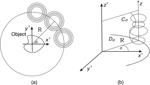
Consider a stack of parallel circles, which have possibly different radii and whose centres are on a line pointing in z-axis, which intersects the circle with radius R centred at the origin of a reference coordinate system. Then suppose the stack is rotated around an object along this circle and that the object is surrounded by the stacks. Any circle is assumed to collect integrals of pressure wave field over its length. This is the analog of the experimental buildup in Citation12, Section 2] for circular integrating detectors.
For our further considerations, we introduce the following notations: Let V the volume surrounded by the stacks and let σ ∈ S1 denote the angle between the x′ axis of the reference coordinate system and the centre of the stack, see the picture in . Then Dσ denotes the cross-section of V with the plane spanned by σ and the z-axis, and Cσ the intersection curve of this pane and the circles on the stack. Sometimes it will be convenient to use the notation {σ} × C for the set of points (σ, y0) on Cσ. Finally,
(5)
denote the parallel circles that are centred on the z-axis (). Here y ≔ (r, z) ∈ ℝ2, where z and r are the height and radius of the circles, respectively. Note that for each point on the curve Cσ there is a circle cσ,y passing through it and that this circle is unique up to the sign of the radial variable r. For
, let Gev(z, r) ≔ G(z, |r|) and define the spaces
of smooth compactly supported functions which are even in the r variable.
In the following, we shall prove that circular detectors yield a similar two-step reconstruction procedure as for integrating line detectors Citation2, Theorem 2.1]. Before we can state the corresponding theorem, we make the following definitions.
Definition 2.1 (Circular Radon transform)
By
(6)
we denote the circular Radon transform, which maps a function f to integrals over circles in the planes ℝ2 × {z}, which centres on the circle with radius R and centre 0 in this plane.
Due to the definition of cσ,y, ℛf is an even function in the r variable. Circular integrating detectors are modelled as a device performing the circular Radon transform of the pressure wave field for restricted radii. This leads to the following definitions:
Definition 2.2 (Forward operator)
The forward operator in cylindrical coordinates is
(7)
Here p is a solution of IVP (1–3).
Definition 2.3
The operator
(8)
maps a function
to G ∈
, where G(σ, ·) is the restriction to C × [0, ∞) of the solution of
(9)
(10)
(11)
Initial value problem (9–11) has a unique solution that can be given in an explicit form, which is due to the connection of (9–11) to the 2D wave equation and, in particular, to the existence of transformations that interwine the second derivative with the Bessel operator r−1∂rr∂r. The operator we are dealing with is the Weyl transformation
(12)
in the r variable. The Weyl transform is linear and satisfies the interwining property Citation27
(13)
This leads to the following proposition:
PROPOSITION 2.1
For a fixed σ ∈ S1, the unique solution of (9–11) is given by
(14)
with
Proof
From the interwining property (13), it follows that P is a solution of (9–11), if and only if 𝒲0P is a solution of the IVP
(15)
(16)
(17)
The unique solution of (15–17) is given by 𝒜𝒲0Fσ, so we have that 𝒲0 P = 𝒜𝒲0Fσ and the claim follows.▪
Theorem 2.1 is a generalization in Citation2, Theorem 2.1].
THEOREM 2.1
The forward operator (7) decomposes into the product of the linear operators 𝒬 and ℛ, i.e.,
(18)
Proof
Let p be the solution of (1–3), fix σ ∈ S1 and define
(This is the same expression as in (7) but in this case y is not restricted to Cσ.) From the definitions of 𝒬 and P, it follows that we it is sufficient to show that 𝒫σ satisfies (9–11) with F = ℛf.
First note that initial data (10) and (11) immediately follow from (2) and (3). It remains to show that 𝒫σ solves the modified 2D wave Equation (9). By inserting the well-known expression
for the Laplacian in cylindrical coordinates in (1) and integrating over α, we obtain
The last term cancels because cσ,y is a closed curve; therefore 𝒫σ satisfies (9).▪
The decomposition of the original problem into a sequence of lower dimensional problems is the basis of the two-stage procedure for three-dimensional image reconstruction with circular integrating detectors. Before going into details we explain how it works in principle.
| 1. | For each of the directions σ ∈ S1 solve
Figure 2. Reconstruction of the initial pressure from its circular Radon transform. 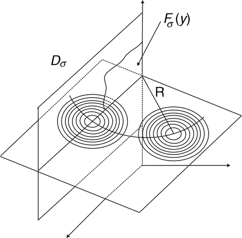 | ||||
| 2. | Again from , it is clear that for a fixed z = z0, the map
| ||||
A novel analytic reconstruction formula for reconstructing Fσ in (19) is derived in the following Section 3.
3. Analytic inversion formula
The first step in the reconstruction algorithm is to solve Equation (19). We outline a strategy that uses the Fourier, Hankel and Cosine transformation to derive a reconstruction in the case when the circular stack is a cylinder. In this case, Cσ is a line consisting of the points (r0, z). In the following computations, we write F(y) instead Fσ(y) in order to keep our notation simple.
It is well known that after going into Equation (9) with the separation ansatz
(23)
one obtains the ordinary differential equation
(24)
for φ. Its solution is given by the Bessel function φ(r) = J0(rv) of order 0 and therefore, we end up with the family of solutions
(25)
Now consider the function P(y, t) = P(r, z, t), which satisfies (9–11) and try to find a such that the equation
holds. Because of the initial condition (10), i.e. at t = 0, this leads to
which is the inverse Hankel Fourier transform of the function
Citation29 and therefore the function
is given by
Putting all things together, the desired solution of (9–11) is given by
(26)
Since our goal is to determine the initial pressure from the measurements G(z, t) = P(r0, z, t), it is desirable to eliminate the dependence of dv in (26) because the function g does not depend on r. Remember that ω2 = k2 + v2 and therefore
(27)
Plugging this into Equation (26) and setting r = r0, we have
(28)
After this change of the integration variables, we recognize that (28) can be written in the form
where
(29)
(30)
denote the Fourier and Cosine transform in the z and t variable, respectively. Using that 𝒞−1 = 𝒞, gives
(31)
Equation (31) is an explicit formula for the operator 𝒬. Solving (31) for , provided the denominator is not zero, finally gives
(32)
Summarizing the computations above gives the following theorem:
THEOREM 3.1
Let and let G be the restriction of the solution of (9–11). Then G and F are related by (32).
4. Conclusion
In this article, we proposed a novel experimental buildup for PAT using circular integrating detectors. For collecting measurement data, a fibre-based Fabry–Perot interferometer can be used as an circular integrating detector. We showed that the 3D imaging problem reduces to a series of 2D problems. This decomposition can be used to reduce the operation count of derived reconstruction algorithms. We derived an exact reconstruction formula for circular integrating detectors.
The reconstruction formula in Section 3 needs further analysis to handle the effect of the zeros of Bessel functions in denominator. Future work will also be concerned with the numerical implementation of (32), which will investigate the behaviour of the derived reconstruction algorithms for noisy measurement data and 3D reconstruction with circular integrating detectors. There is considerable hope for stable implementation like in Citation30, since inversion formulas in Citation30 for integrating line detectors are quite similar.
Acknowledgements
This work has been supported by the Austrian Science Fund (FWF), Project Y123-INF and project P18172-N02.
Related Research Data
References
- Gusev, VE, and Karabutov, AA, 1993. Laser Optoacoustics. New York: Institute of physics; 1993.
- Haltmeier, M, Schuster, T, and Scherzer, O, 2005. Filtered backprojection for thermoacoustic computed tomography in spherical geometry, Math. Methods Appl. Sci. 28 (2005), pp. 1919–1937.
- Kruger, RA, Kiser, WL, Reinecke, DR, and Kruger, GA, 2003. Thermoacoustic computed tomography using a conventional linear transducer array, Med. Phys. 30 (2003), pp. 856–860.
- Xu, M, and Wang, L-HV, 2006. Photoacoustic imaging in biomedicine, Rev. Sci. Instruments 77 (2006), p. 041101.
- Finch, D, Patch, S, and Rakesh, K, 2004. Determining a function from its mean values over a family of spheres, SIAM J. Math. Anal. 35 (2004), pp. 1213–1240.
- Xu, M, and Wang, LV, 2003. Analytic explanation of spatial resolution related to bandwidth and detector aperture size in thermoacoustic or photoacoustic reconstruction, Phys. Rev. E 67 (2003), pp. 1–15.
- Cox, BT, Zhang, EZ, Laufer, JG, and Beard, PC, 2004. Fabry perot polymer film fibre-optic hydrophones and arrays for ultrasound field characterization, J. Phys.: Conf. Ser. 1 (2004), pp. 32–37.
- Paltauf, G, Schmidt-Kloiber, H, and Guss, H, 1996. Light distribution measurements in absorbing materials by optical detection of laser-induced stress waves, Appl. Phys. Lett. 69 (1996), pp. 1526–1528.
- Burgholzer, P, Hofer, C, Paltauf, G, Haltmeier, M, and Scherzer, O, 2005. Thermoacoustic tomography with integrating area and line detectors, IEEE Trans. Ultrasonics Ferroelectr. Freq. Contr. 52 (2005), pp. 1577–1583.
- Haltmeier, M, Scherzer, O, Burgholzer, P, and Paltauf, G, 2004. Thermoacoustic computed tomography with large planar receivers, Inverse Probl. 20 (2004), pp. 1663–1673.
- Paltauf, G, Nuster, R, Haltmeier, M, and Burgholzer, P, 2007. Thermoacoustic computed tomography using a Mach-Zehnder interferometer as acoustic line detector, Appl. Optics 46 (2007), pp. 3352–3358.
- Haltmeier, M, and Fidler, T, Mathematical challenges arising in thermoacoustic tomography with line detectors, avxiv: math/0610155v4.
- Burgholzer, P, Hofer, C, Paltauf, G, Matt, GJ, Haltmeier, M, and Scherzer, O, 2006. "Thermoacoustic tomography using fiber based Fabry–Perot interferometer as an integrating line detectors". In: in Photonic West, Biomedical Optics. Vol. 6086. San Jose, California, USA: International Society for Optical Engineering; 2006. p. 60861N.
- Grün, H, Haltmeier, M, Paltauf, G, and Burgholzer, P, 2007. "Photoacoustic tomography using a fiber based fabry-perot interferometer as an integrating line detector and image reconstruction by model-based time reversal method". In: in Novel Optical Instrumentation for Biomedical Applications III. USA: SPIE; 2007. pp. 6631–07.
- Oraevsky, AA, and Karabutov, AA, 2003. "Optoacoustic tomography". In: Vo-Dinh, T, ed. Biomedical Photonics Handbook. Vol. 34. Tennessee: CRC Press; 2003. pp. 1–34.
- Andreev, VG, Karabutov, AA, and Oraevsky, AA, 2003. Detection of ultrawide-band ultrasound pulses in optoacoustic tomography, IEEE Trans. Ultrasonics Ferroelectr. Freq. Contr. 50 (2003), pp. 1383–1390.
- Xu, M, Feng, D, and Wang, L-H, 2003. Time-domain reconstruction algorithms and numerical simulations for thermoacoustic tomography in various geometries, IEEE Trans. Biomed. Eng. 50 (2003), pp. 1086–1099.
- Andreev, VA, Karabutov, AA, Solomatin, SV, Savateeva, EV, Aleynikov, V, Zhulina, YV, Fleming, RD, and Oraevsky, AA, 2000. "Opto–acoustic tomography of breast cancer with arc–array transducer". In: Biomedical Optoacoustics. Vol. 3916. CA, USA: San Jose; 2000. pp. 36–47.
- Kruger, RA, Miller, KD, Reynolds, HE, Kiser, WL, Reinecke, DR, and Breast, KGA, 2000. Breast cancer in vivo: contrast enhancement with thermoacoustic ct at 434 mhz-feasibility study, Radiology 216 (2000), pp. 279–283.
- Ku, G, and Wang, L-HV, 2005. Deeply penetrating photoacoustic tomography in biological tissues enhanced with an optical contrast agent, Opt. Lett. 30 (2005), pp. 507–509.
- Manohar, S, Kharine, A, van Hespen, JCG, Steenbergen, W, and van Leeuwen, TG, 2005. The twente photoacoustic mammoscope: system overview and performance, Phys. Med. Biol. 50 (2005), pp. 2543–2557.
- Wang, X, Xu, Y, Xu, M, Yokoo, S, Fry, ES, and Wang, L-HV, 2002. Photoacoustic tomography of biological tissues with high cross-section resolution: reconstruction and experiment, Med. Phys. 29 (2002), pp. 2799–2805.
- Hoelen, CGA, de Mul, FFM, Pongers, R, and Dekker, A, 1998. Three-dimensional photoacoustic imaging of blood vessels in tissue, Opt. Lett. 23 (1998), pp. 648–650.
- Kolkman, RGM, Hondebrink, E, Steenbergen, W, and De Mul, FFM, 2003. In vivo photoacoustic imaging of blood vessels using an extreme-narrow aperture sensor, IEEE J. Select. Topics Quantum Electr. 9 (2003), pp. 343–346.
- Esenaliev, RO, Larina, IV, Larin, KV, Deyo, DJ, Motamedi, M, and Prough, DS, 2002. Optoacoustic technique for noninvasive monitoring of blood oxygenation: a feasibility study, Appl. Opt. 41 (2002), pp. 4722–4731.
- Zhang, EZ, Laufer, J, and Beard, P, 2007. "Three-dimensional photoacoustic imaging of vascular anatomy in small animals using an optical detection system". In: The Eighth Conference on Biomedical Thermoacoustics, Optoacoustics, and Acousto-optics. USA: SPIE; 2007. p. 64370S.
- Agranovsky, M, Kuchment, K, and Quinto, ET, 2007. Range descriptions for the spherical mean radon transform, J. Funct. Anal. 248 (2007), pp. 344–386.
- Finch, D, Haltmeier, M, and Rakesh, K, 2007. Inversion of spherical means and the wave equation in even dimensions, SIAM J. Appl. Math. 68 (2007), pp. 392–412.
- Bracewell, R, 1965. The Fourier Transform and its Applications. New York: McGraw-Hill; 1965.
- Haltmeier, M, Scherzer, O, Burgholzer, P, Nuster, R, and Paltauf, G, 2007. Thermoacoustic tomography & the circular Radon transform: Exact inversion formula, Math. Models Methods Appl. Sci. 17 (2007), pp. 635–655.