Abstract
In order to image the shear modulus in soft tissue, for medical diagnosis, given one component of measured displacements as a function of time on an imaging plane, two related direct finite element-based inversion algorithms are presented. One algorithm is based on the governing equations expressed in the frequency domain, and the other is in the time domain. The algorithms consider the complete equations of isotropic, small deformation, elasto-dynamics, where the hydrostatic stress is also treated as an unknown. The algorithms reconstruct both the shear modulus and hydrostatic stress fields, and regularization is used to stabilize the hydrostatic stress recovery. An algorithm is also developed for reconstructing the second displacement component, while simultaneous finding a smooth approximation to the measured displacement component to reduce noise. Shear modulus reconstruction results from both algorithms, using experimental ultrasound measurements on a tissue-mimicking phantom, are presented, and the merits and drawbacks of each algorithm are discussed.
1. Introduction
Elastography is a novel imaging technique, which maps the elastic properties of tissue, such as Young's modulus or the shear modulus (which is proportional to Young's modulus), in an anatomically meaningful presentation to provide useful clinical information for diagnosis Citation1. In early elastography work, simplifying assumptions were used to generate images associated with elastic properties relatively easily from measurements of tissue motion. For example, Ophir et al. Citation2 solved the 1D Hookean equation for the stiffness from uniaxial measured strains in space. In that work, they assumed that the stress field is uniaxial and constant in space, which is only true for an homogeneous medium with an infinite-size compressor. In vibration amplitude sonoelastography, the vibration amplitude pattern map was associated with the stiffness where low amplitude areas were simply interpreted as stiff regions Citation3. Despite the simplifications, very promising results were obtained in these early works. To obtain more quantitative and accurate elastographic images, elastography has started to be considered within the framework of inverse problem solutions, since in elastography, the goal is to reconstruct mechanical properties of tissue based on the measured displacements, without any knowledge about the presence, location, or shape of abnormal regions. In this work, we focus on dynamic elastography, where the displacements resulting from a transient pulse are measured on an interior plane in the body. This represents a rich data set from which to reconstruct the elastic shear modulus Citation4.
In most of the dynamic elastography literature, where the displacements resulting from a dynamic excitation are measured and used to reconstruct the elastic shear modulus field, the equations of elasto-dynamics are simplified by assuming local homogeneity of the shear modulus and neglecting the gradient of the hydrostatic stress field, giving the Helmholtz equation
(1)
where ρ is the density, u is the displacement and μ is the shear modulus. With this equation, the displacement components decouple allowing for a reconstruction based on only one measured component. Fink and co-workers used this equation for shear modulus reconstruction by solving directly in both the time domain Citation5 and in the Fourier domain Citation6,Citation7 given transient data. Manduca et al. Citation8 used local frequency estimation following the approach that was originally proposed by Knutsson et al. Citation9 to estimate shear stiffness from time harmonic data. One disadvantage of local frequency estimation is that the resolution of the reconstructed shear stiffness image is limited to only half of a wavelength into a given region. McLaughlin et al. Citation10 developed a novel method to invert the Helmholtz equation, where they separated the Fourier transform of the displacement data into phase and amplitude and then applied spatially varying smoothing filters designed to equalize the variance across the image. An important advantage to all of these methods is that they are computationally fast as they solve for the shear modulus locally using direct inversion methods that do not require iterations.
Other researchers have proposed methods that start from the complete equations of elasto-dynamics, but make the same simplifying assumptions so that they are effectively still in solving the Helmholtz equation. Sinkus et al. Citation11 proposed a method where the curl-operator is applied to the equations of elasto-dynamics and, neglecting gradients in the Lamé parameters, eliminated the term associated with the hydrostatic stress. This approach has the disadvantage of requiring third-order spatial derivatives of the data. Romano et al. Citation12 presented a novel finite element-based technique where, by integrating the variational statement of the governing equations by parts twice, all derivatives on the displacement field are eliminated, and then, through appropriate choice of weighting functions, the unknown traction boundary conditions are eliminated from the equations. However, in integrating by parts the second time, they neglected the gradients in the elastic moduli, and ultimately, they also neglected the gradients in the hydrostatic stress field. Thus, the same assumptions are used that reduce the equations of elasto-dynamics down to the Helmholtz equation.
Recently, McLaughlin and Renzi Citation13,Citation14, have developed a method for reconstructing the shear wave speed for transient elastography and supersonic shear imaging, where they first find the arrival times of the transient, propagating wave, and then solve for the wave speeds using the Eikonal equation, which does not assume that the shear modulus is locally constant. This method also has the advantage that it only requires first-order spatial derivatives.
Several researchers have developed iterative methods for reconstructing the shear modulus, where they do consider the complete equations of elasto-statics or elasto-dynamics. In these methods, the general idea of the reconstruction algorithm is to find the best stiffness distribution in order to minimize the difference between the measured displacements from the experiment and the calculated displacements from the mathematical model. An important strength of these methods is that no derivatives of the measured displacements need to be calculated, thus, these methods are robust against noise in the data. However, iterative methods are less efficient than direct inversion methods, since they do require iterations and because the forward problem needs to be solved on the whole problem domain at each iteration. In addition, since the forward problem needs to be solved, boundary conditions, that are not typically well-known, are required. If, for example, the measured displacements are used, then the measured displacements on the boundary are treated as exact, while the interior measured displacements are not (a best fit to these is all that is required), and so the measured boundary displacements are overweighted. Kallel et al. Citation15 and Oberai et al. Citation16 applied their iterative inversion methods to quasi-static compression elastography and Van Houten et al. Citation17–20 and Fu et al. Citation21 to time harmonic elastography using MRI and ultrasound, respectively. All of these iterative inversion methods use a finite element-based algorithm. In each case, they solve for either two independent elastic parameters (assuming isotropy) or just the shear or elastic modulus, assuming a relationship between the shear or elastic modulus they are solving for and a second, independent elastic constant.
In this article, we use a direct, finite element-based, inversion approach for recovering the shear modulus and hydrostatic stress given time-dependent displacement measurements resulting from a transient pulse, considering the complete equations of elasto-dynamics. The problem to be solved is to find the shear modulus distribution that best satisfies the governing equations, i.e. equations of elasto-dynamics, for the given displacement field. The main advantage of this approach, relative to iterative methods, is that it is fast as it does not require iterations nor a forward solution on the whole domain. Furthermore, the solution may be found on small sub-domains, which also increases the algorithm speed. A second advantage, relative to iterative methods, is that it does not require boundary conditions. The disadvantage of this method, as compared to iterative methods, is that it requires first derivatives of the measured displacement data, which is still better than most direct inversion methods that typically require second derivatives. To overcome this disadvantage, the data is first filtered and then an averaging derivative method Citation10,Citation22, which is designed for taking derivatives of data with noise, is applied. This is an extension of earlier work Citation23, where only time harmonic displacements were considered. In Citation23, the importance of considering the hydrostatic stress, which, as mentioned above, is frequently neglected, was shown.
Two algorithms are presented, one solves in the frequency domain and the other in the time domain. In the frequency domain, only the dominant frequency is considered. The primary advantage to solving in the frequency domain is that it reduces the problem size by eliminating the time dependency of the hydrostatic stress, which is treated as an unknown to be recovered. An additional advantage is that the data is automatically smoothed and all the measured time frames are considered when the Fourier transform is taken. An advantage to solving in the time domain is that all the frequency content in the data are considered, not just the dominant frequency.
The two approaches are used for reconstructing the shear modulus field given displacement data from the transient elastography experiment, developed by Fink and co-workers Citation5, performed on a tissue-mimicking phantom. The data consists of one component of the displacement field in a plane as a function of time following a transient excitation on the surface of the phantom. Since the reconstruction algorithms require both displacement components in the imaging plane, a method for reconstructing the second displacement component, assuming volume preserving deformation and that the component out of the plane is negligible, while simultaneously finding a smooth approximation to the measured component is developed and used. The results from the two approaches are compared.
2. Methods
2.1. Forward problem
We first present the governing equations assuming linear elastic, isotropic, dynamic tissue motion. While tissue typically exhibits anisotropic and viscoelastic behaviour, this is presented as a first step and for comparison with other algorithms with similar limitations. Details about the reasonableness of these simplifications are explained very well in Ophir et al. Citation24. Let the tissue region of interest be defined as Ω, and the dynamic motion be defined by the displacement field, u(x, t), which depends on position x ∈ Ω and time t ∈ τ. The usual forward problem is to find the displacement, u(x, t), and hydrostatic stress, p(x, t), fields that satisfy the following system,
(2)
(3)
(4)
(5)
(6)
(7)
where μ(x) is the shear modulus, which depends on position, ρ is the density, λ(x) is a Lamé parameter, and ei are an orthonormal set of basis vectors defined on ∂Ω, the boundary of Ω. Equations (2) and (3) together are the balance of linear momentum. It should be noted that for soft tissue, the Lamé parameter, λ, which is associated with the elastic resistance to volume change, is about six orders of magnitude higher than the shear modulus, μ, which characterizes the tissue's elastic resistance to shape change. A typical value for λ is 2.3 GPa, while μ is of the order of kPa, thus, λ(x) ≫ μ(x). For this reason, tissue is frequently referred to as nearly or relatively incompressible. In the case of nearly incompressible elastic behaviour, the elastic relations should be expressed in a mixed formulation, as given in Equations (2) and (3) where the hydrostatic stress, p, is introduced as an additional variable, for stability purposes when solving Citation25. Furthermore, it should also be mentioned that, in comparison to μ, λ and ρ do not vary much in soft tissue Citation26. This is because λ and ρ are associated with the resistance to volume change and the density, respectively, and these properties, for soft tissue, are close to that of water because soft tissue is 70–80% water. For this reason, in this work the density, ρ, is treated as constant and known. Equations (4) and (5) are boundary conditions on the displacements and tractions, and Equations (6) and (7) are initial conditions. Equations (2) and (3), together with boundary conditions (4) and (5), and initial conditions (6) and (7) yield a boundary and initial value problem which can be solved for the displacement and hydrostatic stress fields if μ(x), λ(x), ρ, ŭi,
, u0, and
are known. Finally, for completeness, either type of boundary condition must be specified at each location on the boundary in each direction without overlap, i.e. ∂Ω1i ∪ ∂Ω2i = ∂Ω and ∂Ω1i ∩ ∂Ω2i = ∅ for the time period of interest.
2.2. Direct inversion method
We use a finite element-based method for solving the inverse elastography problem for the shear modulus and hydrostatic stress given displacement data. Let the hydrostatic stress p(x, t) and shear modulus μ(x), be approximated in terms of typical finite element basis functions such that
(8)
(9)
where superscript h indicates a finite-dimensional approximation, and ψγ and
are finite element basis functions for the hydrostatic stress and shear modulus fields, respectively. Greek subscripts refer to finite element basis function numbers. Overbar (-) denotes co-efficents of interpolating functions. The inverse problem is solved by minimizing the residual of the equations of motion with respect to the finite-dimensional approximations of the shear modulus and hydrostatic stress given prescribed displacements. We consider applying this direct inversion approach in both the frequency and the temporal domains.
2.2.1. Direct inversion in the frequency domain
We can transform the governing Equations (2) and (3) from the time domain to the frequency domain by taking the Fourier transform in time. Selecting the maximum observed frequency component, ωm, as we expect the maximum information content at this frequency, we obtain the following equations in terms of the Fourier transforms of the displacements, û(x, ωm), and hydrostatic stress, ,
(10)
(11)
These are the same governing equations considered for the time harmonic case described in Park and Maniatty Citation23.
We now take the weak form of Equation (10) by multiplying by an admissible test function and integrating by parts in the usual way. Substituting in the finite-dimensional approximations using (8) and (9), where now the interpolation in (8) is taken to be the interpolation of the Fourier transform of the hydrostatic stress field and is a function of space only, and introducing basis functions , which represent the finite element basis functions for the test function, yields
(12)
which is to be solved for the co-efficents of the interpolants,
and
. This results in a system of equations of the form
(13)
where {μ} and
represent the assembled co-efficents of the interpolants for the shear modulus
and Fourier transform of the hydrostatic stress
. Matrices
, [Ĝ], and
are co-efficent and force matrices which are assembled from the following element matrices (using indicial notation for clarity)
(14)
(15)
(16)
where Roman subscripts (i, j) represent spatial degrees of freedom and, j ≡ ∂/∂xj. Also, Ωe ⊂ Ω is a finite element in the region of interest, and
is any part of the element boundary that also lies on the region of interest boundary. All terms in above equations are known except the traction boundary conditions in Equation (16). In order to solve this system, the equations associated with the unknown boundary tractions are ignored, and a least square fit to the remaining equations for the shear modulus and hydrostatic stress is solved. Note that the Fourier transform of the displacement field appearing in (14) and (16) is obtained by taking the Fourier transform of the discrete displacement data at the central frequency. By taking the Fourier transform, all the time frames are considered and some of the noise in the data is removed. For stability, a spatial filter is also applied to the displacement data before computing the displacement gradients, and spatial regularization is used to weakly enforce the Fourier transform of the hydrostatic stress to be finite and smooth. For efficiency, the system is solved on overlapping sub-domains. For further details of the algorithm, see Park and Maniatty Citation23.
2.2.2. Direct inversion in a temporal domain
We solve the inverse problem for the shear modulus in the temporal domain using a space-time finite element formulation. By integrating by parts in both space and time, we not only reduce the spatial derivative that is taken on the data from two to one, but also the time derivative. Taking the weak form of Equation (2), and substituting in the finite-dimensional approximations (8) and (9) yields
(17)
where
represents a finite-dimensional approximation of an admissible test function and the time domain of interest is defined as the interval τ = [0, tf]. For emphasis, we explicitly show that the shear modulus, μh(x), is only a function of space, while the hydrostatic stress, ph(x, t), is a function of space and time. This results in a system of equations of the same form as shown in (13) for the co-efficents of the interpolations for the shear modulus
and the hydrostatic stress
. Specifically
(18)
Matrices [K], [G] and {f} are formed by assembling the following element matrices (using indicial notation for clarity)
(19)
(20)
(21)
where [tei, tef] ⊂ τ is the time interval and Ωe ⊂ Ω is the spatial domain of a space-time finite element e.
The above system of equations is to be solved for the co-efficents of the interpolations of the shear modulus field, μ, which is the goal of this work, and the hydrostatic stress field, p, which is of less interest, but is unknown and may not be negligible. A potential advantage of solving in the temporal domain versus the frequency domain, described in the preceding section, is that more information content from the rich data may be used as all frequency components, i.e. all the displacement data with time, may be considered, not just the central frequency. The downside is that now the hydrostatic stress is a function of both space and time, which greatly increases the number of unknowns, i.e. the vector of co-efficents is much longer because the interpolations are in space and time, even though the parameter of interest, the shear modulus, is only a function of space. In order to balance the efficiency while also using the time-dependent data, only a subset of the time frames may be used. As in the frequency domain, the boundary traction term is not known. Thus, as was done in the frequency domain, the system is solved neglecting the equations associated with this term (see Park and Maniatty Citation23 for details). Furthermore, the time domain boundary term is less accurate, so the equations associated with this term are also discarded. Thanks to the richness of the data, this still leaves a system of equations with more equations than unknowns.
Several issues still need to be considered when solving the system defined by Equations (18–21). First, frequently only one component of the displacement field in a plane is measured, thus, all the components of the displacement gradient cannot be computed. If we assume that the excitation is such that the displacements are primarily in the plane, and using the fact that the deformation is nearly incompressible, it is possible to reconstruct the second component of the displacement in the plane. In a similar fashion, if two components are measured on two nearby planes, it is possible to obtain the third displacement component. In the process of reconstructing the unknown displacement component, we also find a smooth approximation to the known displacement components. This process can be thought of as both filtering the data (enforcing smoothness) as well as reconstructing one unmeasured displacement component. We accomplish this by finding the displacement field that lies in a finite-dimensional space defined in terms of finite element basis functions, , that minimizes the following function at each discrete time
(22)
where α1, α2i and α3i are weighting co-efficents, nd is the number of degrees of freedom (2D or 3D) considered, Φi is a switching parameter that is one if i is a component, which has been measured and is zero otherwise, {ui} represents the assembled nodal displacements (
) for the i-th component, and
are the corresponding measured displacements. The first term in (22) enforces incompressibility and the second term enforces smoothness on the recovered displacements. The last term in (22) forces the recovered displacements to be close to the measured displacements for the components measured, where here, the finite element nodal points are taken to coincide with the measurement locations. The weighting co-efficents α2i and α3i have the additional subscript i to indicate that they are not necessarily the same for different displacement components.
The weighting co-efficents, α1, α2i and α3i, in Equation (22) are chosen with the following considerations. First, only the relative values of the weighting co-efficents affect the result. Since the tissue is nearly incompressible, and noting that λ, which ‘penalizes’ the compressibility (Equations (2) and (3)), is roughly six orders of magnitude higher than μ, we expect α1 to be the highest weighting co-efficent to strongly enforce the incompressibility, and it should not be more than six orders of magnitude higher than the other weighting factors, both based on the physics and to avoid ill-conditioning in the resulting system of equations. The ratio α2i/α3i associated with the measured displacement components represents the balance between enforcing smoothness and enforcing this component to be close to the measurements. Thus, it should depend on the signal to noise ratio, where it would be lower for high signal to noise ratios, and vice versa for low signal to noise ratios. This ratio should not exceed one so that the condition of being close to the measured data is not outweighed by smoothing. Finally, it remains to define the ratio α2j/α2i, where j indicates the component to be reconstructed which has not been measured and i is associated the measured component. The parameter α2j acts as a regularization parameter to provide stability in the reconstruction. The ratio α2j/α2i should be between 0.1 and 10−4 to provide stability and avoid excess smoothing. The values chosen in the examples later were chosen by visualizing the data and choosing values that satisfied the conditions above and gave a smooth displacement field that matched the given data well without high spatial frequency noise.
Minimizing the above function (22) with respect to the nodal displacements results in a linear system of equations of the following form
(23)
where the matrices [H] and {b} are formed by assembling
(24)
(25)
where δij represents the Kronecker delta. In addition, in order to solve for an unmeasured component of the displacement field, a boundary condition on that displacement field must be prescribed to prevent rigid body motion. This is accomplished by fixing a single point. Solving for the smooth displacement field using the above formulation at each time is quick because the system of equations in (23) is linear, and the matrix [H] is defined by the grid. If the measurement grid is defined a priori, this matrix can be inverted a priori, so that only back substitution is needed to find the displacements at each time.
Once the displacement components are determined, a second issue is that the displacements must be differentiated once in space for Equation (19) and once in time for Equation (21). The grids in space and time on which the data are measured are also used for the finite element nodal grid. The spatial derivatives are obtained using the averaging derivative method of Anderssen and Hegland Citation22. In that procedure, the derivative at a given location is taken to be the spatial average of the finite difference approximation over some specified window size. The advantage of this method is that it does not increase the variance of the derivatives. This method was also used in McLaughlin et al. Citation10. Here, the data in time is relatively smooth, so the time derivatives are directly computed using a finite difference scheme, without local averaging.
The system defined in (18) is over-determined, but is also unstable. The instability arises from the hydrostatic stress part of the reconstruction. This instability arises because the governing Equation (2) is in terms of the gradient of the hydrostatic stress, and thus, the hydrostatic stress field should only be determinate to within a constant. Furthermore, due to the near incompressibility, even in the forward solution care must be taken to avoid instabilities associated with the hydrostatic stress field Citation25. A space-time regularization procedure is applied to stabilize the hydrostatic stress by weakly penalizing the L2 norms of both the magnitude and the gradients of the hydrostatic stress field. We solve for the best shear modulus and hydrostatic stress fields fitting Equation (18) in a least squares sense subject to the regularization on the hydrostatic stress by minimizing
(26)
where β1, β2i, and β3 are regularization parameters, Di is a differential operator in space along direction i, and Dt is a differential operator in time. Minimizing (26) yields the following system of equations
(27)
where matrix [I] is an identity matrix.
The above system of equations is dense, but can be solved efficiently on local sub-domains within the region of interest because we are solving for interior parameters given interior displacements. Thus, there is no alteration of the problem definition when the whole domain is divided into multiple sub-domains, and this greatly reduces the computational time. However, discontinuities in the solution may arise on the sub-domain boundaries, so the sub-domains are overlapped to provide a smooth solution by averaging the solution in the overlap region and neglecting the solution right on the boundary of the sub-domains, which is typically not accurate due to poorly defined boundary conditions.
3. Results
The algorithms described in the preceding section are tested on an experimental data set provided by the laboratory of Mathias Fink. The data is measured using the transient elastography method presented in Sandrin et al. Citation5 on a tissue-mimicking phantom. The phantom consists of an homogeneous background with a 5 mm radius cylindrical inclusion. It is composed of an agar-gelatine mixture with a 3% concentration of agar powder, which is uniformly spread throughout to obtain homogeneous echogenicity. The background has a 2% gelatine concentration, and the inclusion has a 4% concentration of gelatine, which makes the inclusion about four times stiffer than the background.
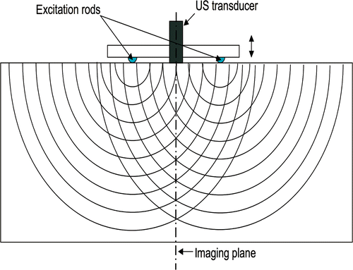
The excitation device is composed of two parallel rods between which an ultrasound array is placed, also in parallel (). The two rods vibrate identically and each apply a vertical displacement with 1 mm amplitude on the top surface of the phantom. The imaging plane is equidistant from the two rods, with the cylindrical inclusion perpendicular to the imaging plane and vibrating rods. Due to the symmetric configuration of the experiment, the transverse displacement vectors caused by each rod are superimposed in the imaging plane and the out-of-imaging plane components of the displacement cancel each other out. A linear array of 128 ultrasound transducers acquires the RF signals at 1000 frames/s. The field of view is 41.91 mm × 67.492 mm with 128 × 95 pixels, and 99 frames are recorded. Only the displacement along the excitation direction is measured. See Sandrin et al. Citation5 for details about the experiment, but note that the tissue mimicking phantom used in this study has a different agar-gel concentration and size of inclusion from the phantom described in Citation5. Results from the experiment with a 60 Hz central frequency of excitation are presented. The same data was also tested for reconstructing the shear wave speed making use of the propagating wave front to compute arrival times in McLaughlin and Renzi Citation13,Citation14.
Figure 1. Schematic of transient elastography experiment performed in the laboratory of Mathias Fink Citation5. Vibrating rods set up propagating waves. The vertical displacement component, resulting from the propagating waves, as a function of time is recorded on the imaging plane.
A portion of the raw data is shown in . As shown in , the shear waves propagate from top to bottom, and the wave front bends when it passes through the high speed region, where the stiff inclusion is located. Also note that the wave amplitude decays considerably as it propagates inside. This reduces the signal to noise ratio, making an accurate reconstruction more challenging at increasing depths.
Figure 2. Image of raw displacement data used for this study showing propagating shear waves. Waves propagate from top to bottom surface. Only the downward displacement component is measured, in μm. Available in colour online.
The accuracy and resolution of the reconstructed shear modulus, μ, (and hydrostatic stress, p) depend strongly on the precision in the calculation of the displacement gradients in space and time, i.e. ∇u and , respectively. Thus, the spatial and temporal resolutions of the measurements are of primary significance, in addition to the accuracy of the measurement itself. Here, the spatial resolution (grid size) in the horizontal direction is 0.33 mm and in the vertical direction is 0.718 mm, and the temporal resolution is 1 ms. From our prior study for the time harmonic case in Citation23, we showed that data with 5% Gaussian random noise and a spatial resolution of 1 mm is sufficient to detect a 2 mm radius inclusion. The spatial resolution hear is finer, however, the noise level of the experimental data also is higher.
In all of the reconstructions to follow, the finite element interpolation functions for the shear modulus and the hydrostatic stress () and ψγ(x, t)) are constant over each element in space. For the temporal domain case, the hydrostatic stress interpolation is piecewise constant in time. The displacements and weighting function interpolants
are linear in space and time over each finite element.
3.1. Result from frequency domain inversion algorithm
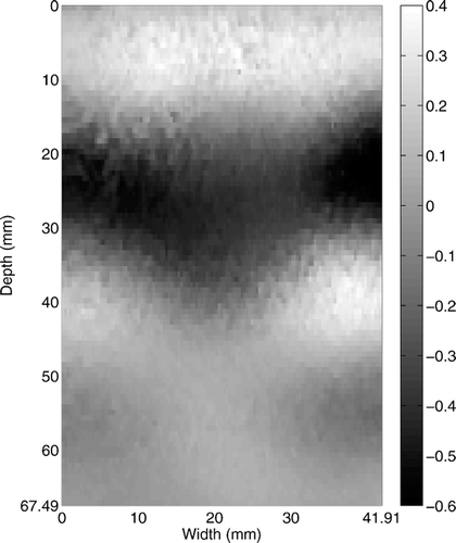
First, we show the results using the algorithm described in Section 2.2.1, where the shear modulus reconstruction is performed in the frequency domain. A temporal Fourier transform is performed on all 99 frames of the propagating shear wave images to extract the time harmonic motion at a dominant frequency. Due to the visco-elasticity of the agar-gel phantom, although not as strong as in soft tissue Citation27, a frequency dispersion exists. It is caused by the frequency dependency of the speed of the propagating wave and makes the dominant responding frequency of the object vary with spatial location. Although the central frequency of the excitation is 60 Hz, the dominant reacting frequency of the phantom is at 70.71 Hz in most regions. shows the Fourier transformed displacement at 70.71 Hz.
Figure 3. Fourier transformed displacement component along downward direction from ultrasound measurement (in μm). Although the central frequency of the excitation is 60 Hz, the dominant frequency of the time harmonic response is at 70.71 Hz. Available in colour online.
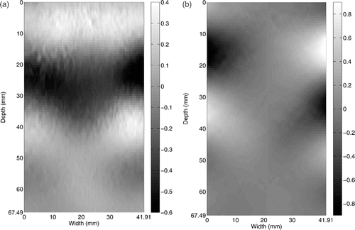
Since the displacement data from the ultrasound measurement has only one-directional component, which is parallel to the ultrasonic beam in the downward direction, we reconstruct the second in-plane component (horizontal component) of the Fourier transform of the displacement, while also smoothing the Fourier transform of the measured component by minimimizing Equation (22). We set α1 = 1000, α3x = 100, α2x = 100 for the vertical direction, and α2y = 0.1 for the horizontal direction. These parameters strongly enforce the divergence-free constraint and the requirement that the computed vertical displacement must be close to the measured displacement, and enforce smoothness relatively weakly, but sufficiently to provide a stable inversion. The smoothed displacements (Fourier transformed), ûh, for both directions are shown in . Despite the smoothing, note that there is still some noise in the displacements. Thus, care must be made in differentiating the data.
Figure 4. Smoothed Fourier transform of the displacements as a result of the minimization of Equation (22): (a) Smoothed vertical displacement, (b) reconstructed horizontal displacement from vertical displacement (in μm). Available in colour online.
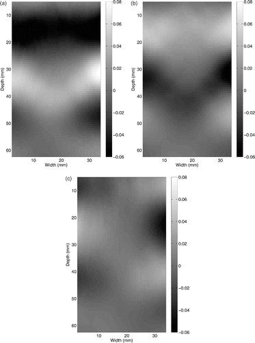
As mentioned before, the gradient of the displacements are calculated by the averaging derivative method proposed by Anderssen and Hegland Citation22. The results are shown in . Vertical and horizontal directions are defined as X and Y directions, respectively. A window size of 15 × 7 (horizontal × vertical), about each grid point, is used in computing the spatial derivatives. In addition to the spatial smoothness, the computed strain should satisfy the nearly incompressible behaviour, thus, Figure should be almost identical with opposite signs, which they are.
Figure 5. Strain values obtained using averaging derivative method (×10−3): (a) εxx, (b) εyy (c) εxy. Vertical and horizontal directions are defined as X and Y directions, respectively. Available in colour online.
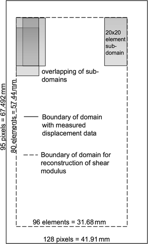
Using a procedure, analogous to that given in Equation (27), but in the frequency domain, the shear modulus and hydrostatic stress fields are reconstructed. Here, the regularization parameters on the hydrostatic stress are taken to be β1 = 10−8, β2x = 0.5, and β2y = 0.01. Given the size and spatial resolution of the ultrasound data, which is used for our finite element discretization for the Fourier transformed displacement field, there are 7680 (96×80) shear modulus and the hydrostatic stress values to reconstruct (taken as constant over each element). Note, due to the windowing for the averaging derivatives, the domain size is reduced as derivatives cannot be computed near the edges of the domain. The problem domain is decomposed into an array of 20 × 16 = 320 overlapping sub-domains (), each with 20 × 20 element size, and where each subsequent sub-domain is off-set by four elements over (or down). The shear modulus is taken as the average reconstructed value in the overlapped regions.
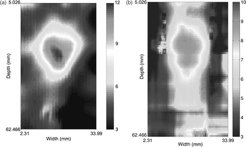
shows the reconstructed shear modulus distribution. The inclusion is well-detected, and the shear modulus, at the centre of the inclusion, and the background are accurately reconstructed. Although the boundary of the inclusion is smeared due to the data smoothing and averaging derivatives, which are necessary because of the large noise level in the data, the size of the inclusion is reasonably well predicted too.
3.2. Result from temporal domain inversion algorithm
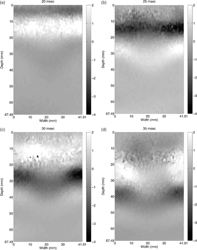
The shear modulus was also reconstructed using the space-time inversion algorithm, described in Section 2.2.2. As in the frequency domain case, the horizontal displacement component in the plane needs to be reconstructed, but now for each time frame of interest. The same algorithm, which both solves for the unknown displacement component and finds a smooth displacement field close to the measured displacement field, is used with α1 = 1000, α3x = 100, α2x = 1 for the vertical direction, and α2y = 0.1 for the horizontal direction in Equation (22). shows the resulting computed displacement field at two different times, 20 and 30 ms. The vertical displacements, which coincide with the measured displacements (compare with ), are shown in , and the reconstructed horizontal displacements are shown in . Note that all colourbar scales are equal in this figure. Due to the near symmetric configuration of the experimental setup, the horizontal displacement along the depth near the centre is near zero. However, in all other areas, the magnitude of the horizontal displacement is non-negligible. Also note that the smoothness requirement in (22) is only weakly enforced for stability, so the displacements still contain some noise. This noise is compensated for in the spatial derivative calculations using the averaging derivative method Citation22 with the same window size, 15 × 7, as used in the frequency domain case. The data is relatively smooth in time, and a standard central difference is used for computing the time derivatives in Equation (21). A snapshot of the computed strains and velocities are shown in .
Figure 7. Vertical and horizontal displacements at 20 ms, ((a) and (b)) and at 30 ms ((c) and (d)), respectively (in μm). Horizontal displacement is reconstructed using Equation (22). Available in colour online.
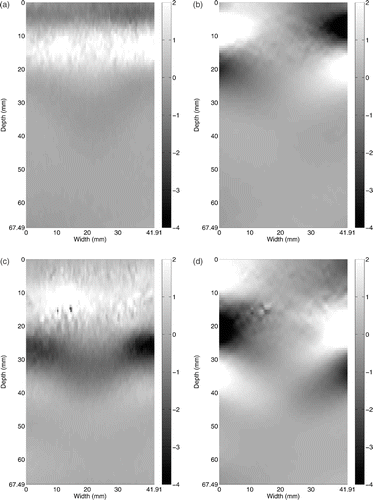
Figure 8. Snapshot of computed strain values (×10−3) (a) εxx, (b) εyy and (c) εxy, and velocities (μm s−1) (d) dux/dt and (e) duy/dt, where X and Y are the vertical and horizontal directions, respectively. Available in colour online.
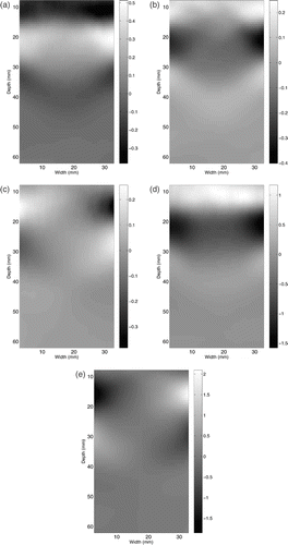
The inverse problem is solved on an array of 8 × 10 = 80 overlapping sub-domains, each with 20 × 20 spatial elements, where the sub-domains are offset by 8 elements. Note, fewer sub-domains are used here than in the frequency domain inversion since the solution on each sub-domain, when the temporal domain is also considered, results in a significantly larger system, as described next.
With a space-time formulation, each sub-domain in space has an additional temporal window. These temporal windows need to be chosen carefully due to the following reasons. First, the propagating waves pass through each sub-domain within a few time frames. Considering the wave speed and geometrical size of the sub-domains, six frames are selected for each sub-domain. If more temporal frames are selected for the reconstruction, it might provide better results, however, in the temporal domain, the number of unknown hydrostatic stresses also increases with the number of time frames as the hydrostatic stress must be resolved for each time. Thus, adding time frames dramatically augments the problem size leading to a longer computation time. Second, each sub-domain has its own temporal window since it experiences the propagating waves at different time frames. In this study, the temporal windows were chosen manually through observation of the propagating waves. Each of the 80 sub-domains then requires solution of 20 × 20 = 400 unknown shear moduli and 20 × 20 × 6 = 2400 unknown hydrostatic stresses. The regularization parameters chosen to stabilize the hydrostatic stress recovery in Equation (27) are β1 = 10−11, β2x = 0.01 (top half), β2x = 0.1 (bottom half), β2y = 0.1, and β3 = 0. Note that a higher value of β2x is used for the lower half of the domain due to the lower signal to noise ratio as the wave propagates deeper into the domain. Conceptually, this is similar, albeit much simpler, to the approach used in McLaughlin et al. Citation10 where the regularization parameter is chosen to be higher in the regions of lower signal to noise ratio with the goal of creating an image of the shear modulus with a uniform variance. In that work, the regularization was associated with the window size used in computing the derivatives. Here, the regularization parameters were chosen to be as low as possible while still enforcing smoothness on the hydrostatic stress field.
presents the shear modulus distribution obtained using the space-time finite element inversion approach. The size and location of the inclusion match well the results in the frequency domain shown in . However, the shear modulus is underpredicted in the centre of the inclusion and the boundary is not as well defined. Furthermore, the inclusion appears more elongated in the depth direction, especially behind the inclusion. Artifacts appear in the lower portion of the figure in the region with a low signal to noise ratio. The primary reason for the poorer reconstruction in the temporal domain as compared to the frequency domain is likely that only six time frames are taken for each sub-domain for efficiency purposes, but may have insufficient information content. For the frequency domain, all 99 frames are used, and the Fourier transform is used to extract out the dominant information. Furthermore, the six frames chosen were not optimized. While more frames may have more information content, they also increase the number of hydrostatic stress unknowns which may also lead to instability.
4. Conclusions
In this article, a finite element-based approach for directly reconstructing the shear modulus distribution from transient displacement data measured using ultrasound is presented. The gradient of the hydrostatic stress field is not neglected here resulting in the additional unknown hydrostatic stress field also needing to be recovered in the algorithm. Since the algorithm presented has the advantages of not requiring iterations and being suitable to use on sub-regions of the domain, it is relatively fast compared to iterative finite element-based algorithms. Two different algorithms are presented which are used to handle the same displacement data set, one which solves in the frequency domain and the other in the time domain. For the time domain algorithm, a space-time finite element formulation is used where the second derivatives appearing in the governing equation in both space and time are reduced to first derivatives through integration by parts of the weak form.
In order to obtain a stable solution given the available ultrasound data, several steps are taken. First, the transient ultrasound data used here consists of only a single component of the displacement in the imaging plane, which is parallel to the direction of the ultrasound beam. A method is presented to obtain the second in-plane component while simultaneously finding a smooth approximation to the measured data using the assumptions that the out of plane displacement is negligible and the displacement field is divergence free. Second, an averaging derivative method is used to calculate the spatial gradient of the displacement. Finally, to remove most artifacts caused by the instabilities in the hydrostatic stress field reconstruction, the inversion algorithm used to find the shear modulus and hydrostatic stress fields includes stabilization of the hydrostatic stress field by simple zero and first order regularization. The sub-domain size used in the reconstruction is selected in spatial and temporal spaces through observation of the propagating wavefront.
The shear modulus reconstructions resulting from both the frequency and temporal domain algorithms show the inclusion clearly and are fairly similar to each other. However, the magnitude of the shear modulus in the centre of the inclusion from the temporal reconstruction is a bit lower and some artifacts arise towards the bottom of the reconstructed image due to the low signal to noise ratio at greater depths. Several issues are brought up to explain these facts. For the solution in the frequency domain, all 99 frames are used to obtain which is used as raw data in the reconstruction. For the temporal domain case, for each sub-domain only six temporal frames are used, which are not optimized. In addition, for the solution in the frequency domain, selecting the dominant single frequency information from the Fourier transformed data automatically removes potentially noisy information. These facts lead to a better solution in the frequency domain.
The results of this study can be used to guide future work leading to improvements in both algorithms. In the frequency domain, the dominant frequency need not be the only frequency considered. Considering additional frequencies and possibly the phase information (see e.g. Citation10) would likely lead to improved reconstructions. In the temporal domain, a more optimal selection of the temporal windows would improve the results. An alternative approach, to address the large number of hydrostatic stress components in the temporal domain recovery, is to use a reduced order model for the hydrostatic stress to reduce the unknowns in the system equations while still allowing more temporal information to be included. Finally, adaptive regularization, both in the averaging derivative window size selection and in the choice of regularization parameters to stabilize the hydrostatic stress solution, where larger regularization is used in regions of lower signal to noise, should be investigated to optimize the reconstructions.
Acknowledgements
The authors thank J.R. McLaughlin, J-R. Yoon and D. Renzi in the Mathematical Sciences Department at Rensselaer for many valuable discussions and M. Fink of ESPCI for sharing experimental data. This work has been supported by the National Science Foundation through grant DMS-0101458 and by the National Institutes of Health through grant 5 R21 EB003000-02.
Additional information
Notes on contributors
Eunyoung Park1
1 Currently at Corning, Inc., Corning, NY
Notes
1 Currently at Corning, Inc., Corning, NY
References
- Gao, L, Parker, KJ, Lerner, RM, and Levinson, SF, 1996. Imaging of the elastic properties of tissue–a review, Ultrasound Med. Biol. 22 (1996), pp. 959–977.
- Ophir, J, Céspedes, I, Ponnekanti, H, Yazdi, Y, and Li, X, 1991. Elastography: a quantitative method for imaging the elasticity of biological tissues, Ultrason. Imaging 13 (1991), pp. 111–134.
- Lerner, RM, Parker, KJ, Holen, J, Gramiak, R, and Waag, RC, 1988. "Sono-elasticity: Medical elasticity images derived from ultrasound signals in mechanically vibrated targets". In: Kessler, LW, ed. Acoustical Imaging. Vol. 16. New York, NY: Plenum; 1988. pp. 317–327.
- McLaughlin, JR, and Yoon, J-R, 2004. Unique identifiability of elastic parameters from time-dependent interior displacement measurement, Inverse Probl. 20 (2004), pp. 25–45.
- Sandrin, L, Tanter, M, Catheline, S, and Fink, M, 2002. Shear modulus imaging with 2-D transient elastography, IEEE Trans. Ultrason. Ferroelectr. Freq. Control 49 (2002), pp. 426–435.
- Bercoff, J, Chaffai, S, Tanter, M, Sandrin, L, Catheline, S, Fink, M, Gennison, JL, and Meunier, M, 2003. In vivo breast tumor detection using transient elastography, Ultrasound Med. Biol. 29 (2003), pp. 1387–1396.
- Bercoff, J, Tanter, M, and Fink, M, 2004. Supersonic shear imaging: a new technique for soft tissue elasticity mapping, IEEE Trans. Ultrason. Ferroelectr. Freq. Control 51 (2004), pp. 396–409.
- Manduca, A, Muthupillai, R, Rossman, PJ, Greenleaf, JF, and Ehman, RL, 1996. "Image processing for magnetic resonance elastography". In: Kim, Y, ed. Medical Imaging 1996. Vol. 2710. Bellingham, WA: Proceedings of SPIE–The International Society for Optical Engineering; 1996. pp. 616–623.
- Knutsson, H, Westin, C-F, and Granlund, G, 1994. "Local multiscale frequency and bandwidth estimation". In: in IEEE International Conference on Image Processing. Vol. 1. Los Alamitos, CA: IEEE Computer Society Press, Proceedings ICIP-94; 1994. pp. 36–40.
- McLaughlin, J, Renzi, D, Yoon, J-R, Ehman, RL, and Manduca, A, 2006. "Variance controlled shear stiffness images for MRE data". In: in 3rd IEEE International Symposium on Biomedical Imaging: Nano to Macro. Piscataway, NJ: IEEE Computer Society; 2006. pp. 960–963.
- Sinkus, R, Tanter, M, Xydeas, T, Catheline, S, Bercoff, J, and Fink, M, 2005. Viscoelastic shear properties of in vivo breast lesions measured by MR elastography, Magn. Reson. Imaging 23 (2005), pp. 159–165.
- Romano, AJ, Bucaro, JA, Ehman, RL, and Shirron, JJ, 2000. Evaluation of a material parameter extraction algorithm using MRI-based displacement measurements, IEEE Trans. Ultrason. Ferroelectr. Freq. Control 47 (2000), pp. 1575–1581.
- McLaughlin, J, and Renzi, D, 2006. Shear wave speed recovery in transient elastography and supersonic imaging using propagating fronts, Inverse Probl. 22 (2006), pp. 681–706.
- McLaughlin, J, and Renzi, D, 2006. Using level set based inversion of arrival times to recover shear wavespeed in transient elastography and supersonic imaging, Inverse Probl. 22 (2006), pp. 707–725.
- Kallel, F, Betrand, M, and Ophir, J, 1996. Fundamental limitations on the contrast-transfer efficiency in elastography: An analytic study, Ultrasound Med. Biol. 22 (1996), pp. 463–470.
- Oberai, AA, Gokhale, NH, and Feijoo, GR, 2003. Solution of inverse problems in elasticity imaging using the adjoint method, Inverse Probl. 19 (2003), pp. 297–313.
- Van Houten, EEW, Paulsen, KD, Miga, MI, Kennedy, FE, and Weaver, JB, 1999. An overlapping subzone technique for MR-based elastic property reconstruction, Magn. Reson. Med. 42 (1999), pp. 779–786.
- Van Houten, EEW, Weaver, JB, Miga, MI, Kennedy, FE, and Paulsen, KD, 2000. Elasticity reconstruction from experimental MR displacement data: initial experience with an overlapping subzone finite element inversion process, Med. Phys. 27 (2000), pp. 101–107.
- Van Houten, EEW, Miga, MI, Weaver, JB, Kennedy, FE, and Paulsen, KD, 2001. Three-dimensional subzone–based reconstruction algorithm for MR elastography, Magn. Reson. Med. 45 (2001), pp. 827–837.
- Van Houten, EEW, Doyley, MM, Kennedy, FE, Paulsen, KD, and Weaver, JB, 2005. A three-parameter mechanical property reconstruction method for MR-based elastic property imaging, IEEE Trans. Med. Imaging 24 (2005), pp. 311–324.
- Fu, D, Levinson, S, Gracewski, S, and Parker, K, 2000. Non-invasive quantitative reconstruction of tissue elasticity using an iterative forward approach, Phys. Med. Biol. 45 (2000), pp. 1495–1509.
- Anderssen, RS, and Hegland, M, 1999. For numerical differentiation, dimensionality can be a blessing!, Math. Comput. 68 (1999), pp. 1121–1141.
- Park, E, and Maniatty, AM, 2006. Shear modulus reconstruction in dynamic elastography: time harmonic case, Phys. Med. Biol. 51 (2006), pp. 3697–3721.
- Ophir, J, Alam, SK, Garra, B, Kallel, F, Konofagou, E, Krouskop, T, and Varghese, T, 1999. Elastography: Ultrasonic estimation and imaging of the elastic properties of tissues, J. Eng. Med. 213 (1999), pp. 203–233.
- Brezzi, F, and Fortin, M, 1991. Mixed and Hybrid Finite Element Methods. New York: Springer; 1991.
- Sarvazyan, AP, Rudenko, OV, Swanson, SD, Fowlkes, JB, and Emelianov, SY, 1998. Shear wave elasticity imaging: a new ultrasonic technology of medical diagnostics, Ultrasound Med. Biol. 24 (1998), pp. 1419–1435.
- Hamhaber, U, Grieshaber, FA, Nagel, JJ, and Klose, U, 2003. Comparison of quantitative shear wave MR-elastography with mechanical compression test, Magn. Reson. Med. 49 (2003), pp. 71–77.
