Abstract
The inverse problem was formulated for the set of equations that describe the following processes: drilling mud circulate, kinetics of well wall cake growth, penetration of the drilling mud filtrate into stratum, redistribution of immiscible phases with salt exchange between water solutions and the resistivity distribution near the well zone. Both the initial saturation for oil and gas phases and the whole permeability of stratum were the desired values. The problem was solved using gradual step-by-step approach that allowed to minimize mean-square deviation of the theoretical points from the data measured by the equipment such as the high-frequency inductive isoparametric logging tool.
1. Introduction
Contemporary interpretation of the data of well electromagnetic sounding is one of the most intense scientific problems. The resolution of this problem requires cumulative results emerging from various areas of scientific research. It is important to emphasize the indispensable role of the electromagnetic theory. There were numerous investigations conducted by famous scientists who utilized the theory of the electromagnetic wave distribution for building the methods of reservoir exploration. For instance, reference Citation1 was one of the initial works. In recent years, the methods of electromagnetic field calculation were developed by many researchers Citation2,Citation3.
In this article, we examine the characteristic properties of spreading electromagnetic waves radiated by a point dipole. The hydrodynamic processes play an important role in solving the problem of data interpretation of well electromagnetic sounding. Those processes involve the penetration of the immiscible fluids and the hydraulics of circulating mud filtrate with the generation of mud cake formation on a well-bore hole. A short overview of the fundamental theory of multiphase flow in porous media is given in Citation4.
Normally, exploratory or production wells are drilled using water-clay mud. The excess pressure lifts cuttings to the ground surface, and is the main cause of clay cake formation on the well bore wall and mud filtrate penetration into stratum. This invasion is accompanied by the displacement of fluids that saturate the pore space. The mathematical model that takes into account the drilling mud circulation in the tube space of the well, the cake formation on the wall of the well, and the immiscible fluid filtration to near the well zone is considered in Citation5. The movement of the drilling mud and mud filtrate invasion are described by the following system of equations of borehole hydraulics and oil, gas and water flow in stratum
(1)
where subscripts i = 0 and i = 1 refer to the gas and water phases, respectively, and the values without a subscript concern the oil phase,
is the filtration coefficient, K is the permeability,
is the viscosity, m and mc are the values of porosity for stratum and cake, the values with indices w, c and b are related to the well, cake and bore equipment, r, z and t are the radial, vertical coordinates and time,
are the values of density for drilling mud solution, oil and water phases,
are the values of the relative phase permeability, si and vi are the values of saturation and velocity, h is the hydraulic head of the pore fluids measured in metres of a water column,
are excess of the drilling mud solution head and the hydrostatic head in stratum, Q(z, t) is the drilling mud discharge, ai is the storage coefficient of stratum, β is the drilling mud consistency, rw is the borehole radius and Rk is the range radius of well,
. The solution of the inverse problem for the common systems presented below makes it possible to effectively estimate the physical parameters of the formation Citation6.
2. Equations of immiscible filtration
The system of Equation (1) can be simplified because the effect of the compressibility is neglected, and one can assign ai = 0. As a result, the system is disjoined into the subsystem governing immiscible phase redistribution near the well
(2)
and the subsystem from the two last equations of the whole system (1) that describe the process of cake growth under the influence of drilling mud flow between the well surface and the drill stem. As one can see, the independent variable z is a hidden parameter for the system of Equation (2). Only the total velocity of fluids V(t; z) and the porosity of strata depend on this parameter indirectly. Using generalized Leverett functions
we obtain the formulas for the calculation of the velocity of phases from Equation (2)
(3)
Introducing the independent variables τ and x and taking (3) into account, Equation (2) are reduced to simple form
(4)
The mobility of every phase depends on its partial saturation and the viscosity. In general, it is defined by the products .
With the presence of the first integral , it would be sufficient to reserve only two out of three equations (4) – for the most mobile gas phase (
) and for the least mobile oil phase (α < 1):
(5)
Assuming that are the initial values of the stratum saturation with oil, water and gas phases, respectively. Considering that only water filtrate penetrates into the stratum during well drilling, the initial data and the boundary conditions for the system (5) are presented by
(6)
If the value of initial oil or gas saturation is greater than the saturation at which the derivative of generalized Leverett function reaches the maximum, the solution of Equation (5) have a discontinuity on the gas displacement front r = rf 0 or the oil displacement front . The discontinuity magnitude is defined by kinematic conditions that result from the integral phase conservation laws Citation7
(7)
In the reverse case, the saturation is continuous, the conditions (7) are automatically satisfied, and the front value of saturation is equal to the value of initial saturation of formation with this fluid. A significant difference between the mobility of gas and oil allows for partial linearization and simplification of the system of Equation (5). This could be achieved using the method presented below.
Let the initial oil saturation s0 and gas saturation be such that
at any time. Taking into consideration the moderate oil mobility, we suppose that there is weak change of oil saturation in the region
. In this case we can assume that
in second equation of system (5). Neglecting the product of the values
and
in comparison with the other terms, this equation is reduced to a form similar to that of one-dimensional two-phase flow
In above-described region, in view of condition (6), the solution of this equation can be presented in the form of an implicit function Citation5
(8)
The gas saturation on the displacement front can be found from the solution of the algebraic equation
(9)
This equation follows from kinematic condition (7). The mean-integral value of residual gas saturation depends only on the gas front saturation and do not depend on the location of the front. Using Equation (9) we can calculate it with the formula
(10)
As the calculations confirm, the value is negligible because the replacement of gas by water is similar to the piston-like displacement. The location of the front displacement is obtained from Equation (8) by setting
.
As is easy to see, the initial oil saturation s0 is the parameter in formulas (8–10). We find the oil distribution in region by integrating the first equation of system (5) for
. The oil displacement process is described approximately by the equation
from which, in view of condition (6), we obtain
(11)
As the last formula demonstrates, this mean integral or residual value of the oil saturation depends only on the oil front saturation, i.e. on the initial saturation of stratum, but not on the location of the front. This can serve to substantiate the splitting method applied here.
Let us consider the case being alternative to previous. Let the initial oil and gas saturation be such that the front portion of the oil displacement passes ahead of the gas displacement, in other words, at each instant of time. Reasoning analogously, we obtain the split system
The first equation is integrated, then second equation is integrated for this system. In the case being considered, the general parameters of the oil distribution are determined using formulas (11) in which the mean integral value of the gas saturation is replaced by the initial value . Moreover, in formulas (10) and (11), the initial oil saturation
should be replaced by the mean integral value of the oil saturation
.
The value of radius of the volume mud filtrate invasion serves as the important parameter and it is expressed by formula
(12)
3. Salt exchange and interaction of water solutions
Saturated with the immiscible phases such as oil, gas and native water, the stratum is a heterogeneous medium with interpenetrating continua. As a rule, any hydrocarbon formation contains some quantity of natural water. The resistivity changes under the influence of processes of the salt transport and the exchange between the mobile water phases inside pores on near the well zone. Since the size of a real strata pore is approximately a fraction of a micron, the process of the phase inner diffusion occurs almost instantaneously and the influence of the external diffusion is insignificant. Let C be the salt concentration of the penetrating solution, N the salt concentration of native water, s1 the mobile water saturation, and the initial natural water saturation.
Processes of the mass transport and the pore diffusion are described according to the equations
(13)
where
is the exchange kinetic parameter. This parameter is negligible because the pore size is very small. In order to simplify the task, it would be enough to use the degenerative variant of the system (13) assuming that
. In this case, using the known value of function
, the balance relation for the total salt mass is considered and the location of the boundary
between fresh and salt water is calculated.
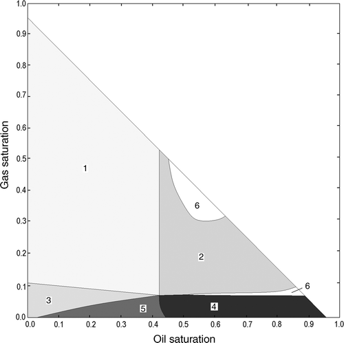
Using the calculated we obtain six cases of the location of the boundary between the water solutions and displacement fronts. Those cases are divided into two groups. First group includes cases 1–3 for
, the rest is for
.
(14)
For all these cases, detailed calculations were realized with using the next algorithm. Summed hydrocarbon phase saturation was introduced by formula where
(0.05, 0.95). On the plain
, the parallel lines were corresponding to the values of the parameter S selected with a small step. There were the intervals on every line on which saturation of hydrocarbon phases agreed with cases 1–3 or 4–6. Then the number of the region was determined for every variant from six cases with the help of formulas for calculating the fronts
. In the calculations, we assumed
. The native water saturation was defined by formula
.
Calculated from the set of initial data, the regions are presented in . Divided into two parts, region 6 occupies the special position on the triangle domain. The narrow part where all the regions come together requires supplementary consideration. This case corresponds to the situation when the velocities of oil and gas are comparable, so even non-significant variations of the fluid saturation result in changing of the location of front displacements for each phase Citation8.
4. Well electromagnetic sounding
One of the effective methods for the investigation of three-dimensional distribution of the resistivity is stimulation of the electromagnetic field and measurement of the phase difference in the coupled coils at hole axis. If the frequencies and the distances between any of the two coils are selected specifically in the way similar to high-frequency inductive isoparametric logging (HFIIL) tool, then all measurements would be identical to the uniform medium. Thus, the measurements by the frequency series allow us to obtain information about the resistivity distribution near the well zone and in the untouched part of the reservoir. The coils are supplied from the alternating current with the specially specified frequencies and serve as the field sources. When the fields are calculated for the distance being greater than the generating coil radius, one may consider coils as a coaxial magnetic dipole. For a uniform conductive nonmagnetic medium, the electromagnetic field is described by the Maxwell system of equations. In a case of running waves, this system leads to d’Alembert equations
(15)
where
is the electromagnetic wave velocity,
is the electrodynamic constant,
are the lag vector and scalar potentials,
is the current density, σ is the electric conductivity of medium, μ is the magnetic permeability, ρ is the charge density, and ϵ is the permittivity. If the electromagnetic field is quasi-stationary, then it is presented as Citation2
where
and
are the electric and magnetic field intensities, relatively. For additional conditions,
and
, system (15) arrives at uniform Helmholtz equations. For the potential Φ, we obtain
(16)
where
is the wavenumber. The thickness of skin layer, h, defines the penetration of the electromagnetic wave and is calculated by the formula
(17)
Let the period of the forced oscillation be , the wavelength be
, where v is the velocity and ϖ is the circular frequency. For the phase velocity,
, the wavelength is
. Consequently,
, and the magnitude of skin layer can be interpreted as a part of the wavelength λ. The fixed phase of oscillation in a unit time is transferred in space by the thickness of skin layer, which depends on the velocity v and the resistivity of medium.
The dipole electric potential is presented as the singular solution of second equation in (15). The solution is given in the form
(18)
where the ort
is directed along the well axis, Θ is the angle between the radius-vector
and the axis z and M is the dipole moment as the limiting value of the product of equal charges and small distance between them. The equipotential surface
crosses points (0, 0) and (0, L) in cylindrical co-ordinates (r, z) and it is calculated taking (18) into account with the formulas
(19)
The dipole moment is defined by the product , where
is the powering alternating current, n is the number of turns and S is the square of one turn. If the electromagnetic field is quasi-stationary, all potential components contain product
, and relation
is independent of time. This means that the equipotential surface is a simultaneously synphased surface. Let L be the distance from the generating coil to the far exploring coil. It is designated the length of sonde. The surface going through closest exploring coil with coordinate (0, L1) is calculated using expression
(20)
It was established theoretically and confirmed experimentally that on the coils the phase difference represents a single-valued function of the resistivity medium Citation5:
(21)
For the medium with non-uniform conductivity and magnetic permeability or permittivity, the shape of the synphased surfaces does not coincide entirely with the shape of the surfaces given by the formulas (19) and (20).
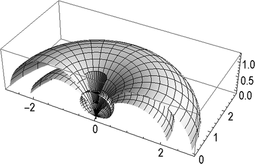
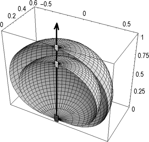
The section of both synphased surface and the eddy current surfaces for the unit length sonde are shown in . Induced by a single dipole at the point of origin, the fix phase of oscillation is transferred along the surface of eddy currents. Here the possible distortion of the shape of the surfaces is not taken into account. The measured phase difference is regarded as some average electrophysical characteristic of the volume between the synphased surfaces (). Calculated with formula (21), the resistivity value is called apparent.
Archie's law Citation9 is used to connect the resistivity and the water saturation s1 in the form of , where R0 is the resistivity of formation saturated with native water. In the general case, it was defined by the experiments that the value Rs could be represented as Citation10
For this empirical formula, is the resistivity of solution with the concentration Cw in mg m−3, and with the temperature T in centigrade degrees, a the empirical constant,
.
As stated in Citation11, the method of probabilistic convolution is effective for interpretation of electromagnetic well sounding. The convolution has the form
(22)
where
is the apparent resistivity obtained with use of ith sonde near the well zone and R(r) is the real resistivity in the same zone,
is the density of the logarithmic normal distribution of the sonde sensitivity and ri is the mode,
.
The parameters of distribution were selected during the process of the sounding data interpretation for the elementary cases of penetration. It was ascertained that the dispersion of all the sounders was identical, and the mode ri defined the location of maximum sensitivity (the focus) of the ith sonde and equaled about half of sonde's length. That conclusion was proved in papers Citation12,Citation13. The convolution (22) turns the real resistivity into the apparent resistivity. Moreover, if we assume that the mode of the distribution is some continuous parameter, so the convolution represents the curve as data of infinite number of sondes. It is possible to make other densities besides the probability density Pi. For example, there is a density which is an average of the weighted volumes contained by every couple of adjacent synphased surfaces (on ). Scanning of the volumes in the radial and vertical directions yields different results concerning the resolution capability and focusing.
5. Formulating and solving of the inverse problem: the examples
During processing of the well electromagnetic sounding by the HFIIL tool or its modification, the phase difference of the signal on the coupled coils is measured. The apparent resistivity is determined as the result of data treatment. The values of the apparent resistivity used to be attached to the focuses are located at half-lengths of the sondes from the hole axis.
For the purpose of the interpretation of sounding data, it is necessary to solve the next inverse problem for the initial system of the equations. It has to find such initial data for the systems of Equations (1) and (2) and coefficient k* in the system
(23)
that mean-square deviation of the sounding points from the convolution (22) must be minimal. Desired parameters are the general results and the object of sounding data interpretation. The system (23) is solved numerically for a sequence of value k* using the implicit finite-difference schemes with iterations. The rest of the parameters are specified in accordance with the conditions of drilling. Initial data and boundary conditions may be given as Citation5
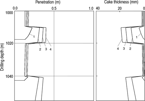
where z0 is the initial depth of drilling and Q0 is the injection rate on depth of the bore bit. In , for the model case the plots of the radius of volume mud filtrate invasion
and the cake thickness
versus time are shown at the interval of depth 1000–1054 m.
Figure 4. Radius of volume mud filtrate invasion and cake thickness vs. time. Notes: Drilling time: 1 − t = 0.4, 2 − t = 1.1, 3 − t = 1.8 and 4 − t = 2.5 h.
The parameters were assumed as follows: the drilling mud viscosity kg (m-h)−1, the density
kg m−3, the initial consistence of drilling mud
, the radius of the drill stem
, the borehole radius
,
, the velocity of drilling wb = 36 m h−1, Q0 = 54 m3 h−1, the porosity of cake and formation
, the external boundary of reservoir Rk = 250 m and the cake filtration coefficient kc = 0.42 × 10⁻⁵ m h−1. Time reckoning began after the replacement of the drilling tool, and fresh drilling started from the depth of 1000 m. The interval of drilling was 1000–1054 m. Formation sounding was at the depth of 1015 m.
A search for approximations of the value Rn as the resistivity of zone adjoining to the well and the value R0 as the resistivity of untouched part of formation is the preliminary stage of solving the problem. Those values depend essentially on the unknown concentration of drilling filtrate mud CP and on the concentration of native water C0. One may take the point of intersection of the line passing through two first point data of the short sondes with the straight line r = rw as the initial approximation for the value Rn. Analogously, the point data of the longest sonde can be used for initial approximation of the value R0. Magnitude of the radius of volume invasion rn is in the relatively short range, so its selection is not difficult. The initial values of the oil saturation s0 and the gas saturation are selected in view of the regions 1–6 from . Initial location of the fronts
and the values of the formation resistivity
between them are calculated using solutions (8)–(11) to the equations of immiscible filtration, salt transport equation (13) and Archie's law. Thus, for oil-and-gas stratum, the resistivity R(r) is presented in the form of a four-step piecewise function Citation13. Substituting the step function into the convolution equation (22), we obtain the apparent resistivity curve
. The selection process continues until mean-square deviation of measured data from the apparent resistivity curve becomes minimal. This relative mean-square deviation is given by the formula
where n is the data number which is equal to quantity of sondes, k is the number of any sonde, Rk is the apparent resistivity of the kth sonde and m is the number of realization.
In the case of oil-and-water stratum, the task of parameters selection is simplified, and the resistivity distribution is given by a three-step function.
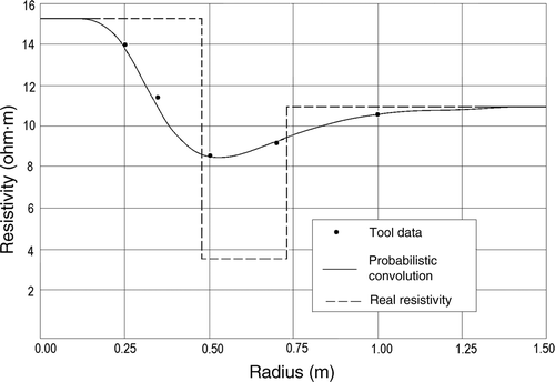
Let us consider the following example. Let the measurements of the HFIIL tool be specified and presented by the points shown in . Using the algorithm, we obtain the following result.
In , the broken line approximates the real resistivity near the well zone, and the continuous curve presents the plot of the convolution (22). The other parameters were calculated as follows: Rn = 15.3 Ohm-m, R0 = 11.1 Ohm-m, Rf1 = 3.83 Ohm-m, rf = 0.74 m, rf1 = 0.48 m, rn = 0.4 m, s0 = 0.7 and = 0.
To estimate the values of radius rn and the cake thickness, a set of calculations was realized for the various values of the oil reservoir permeability.
Defined as the result of interpretation, the radius rn = 0.4 m was obtained for the value of filtration coefficient 0.0044 m h−1. This result corresponds to the permeability
0.12 D where
. Assuming that
, we obtain the complete permeability K = 0.4 D.
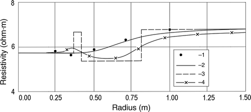
The results of interpretation of data sounding for the real well in oil-and-gas formation are shown in . In that case, the other parameters are calculated as follows: the values of real resistivity Rn = 5.75 Ohm-m, R0 = 6.8 Ohm-m, Rf0 = 5.4 Ohm-m, Rf1 = 6.69 Ohm-m, the radii of fronts rf = 0.364 m, rf0 = 0.805 m, rf1 = 0.41 m, the radius of volume mud filtrate invasion rn = 0.32, initial oil saturation s0 = 0.39 and initial gas saturation . The value of maximal deviation Dev = 1.77% and mean-square deviation Dm = 1.14%. All results were obtained using the method of probabilistic convolution. For comparison, the method of average weighted volumes is given in , shown by the curve with daggers and demonstrates better fitting to real resistivity.
6. Conclusion
Well electromagnetic sounding data interpretation reduced to an inverse problem for the system of equations which describe the processes of drilling mud circulate, mud filtrate penetration into stratum and growth of clay cake, redistribution of immiscible phases near the well zone and salt exchange between water solutions. The changed resistivity of the invasion zone is defined in relative values in accordance with Archie's law. The application of convolution with the logarithmic normal sonde sensitivity expresses this change in view of the apparent resistivity. By minimization of mean-square deviation of the tool, the measured data from the convolution curve of the desired task parameters are determined for the original system of equations. The fluid saturation and the permeability of stratum are such desired parameters.
References
- Doll, HG, 1946. Introduction to induction logging and application to logging of wells drilled with base mud, J. Petrol. Technol. 6 (1946), pp. 148–162.
- Kaufman, AA, and Dashevsky, YuA, 2003. Principles of Induction Logging. Amsterdam: Elsevier; 2003.
- Thadani, SG, and Hall, HE, , Propagated geometric factors in induction logging, SPWLA 22nd Annual Logging Symposium, Mexico city, Mexico Paper WW, 1981.
- Collins, RE, 1961. Flow of Fluids Through Porous Materials. New York: Reinhold Publishing Corporation; 1961.
- Danaev, NT, Korsakova, NK, and Pen’kovskii, VI, 2005. Mass Transport in the Near Well Zone and Electromagnetic Logging of Strata. Almaty: Kazakhstan National University; 2005.
- Korsakova, NK, and Pen’kovskii, VI, 6. Inverse problems of electromagnetic logging in formations, Journal of Geophysical Research Abstracts . Nice, France: 1st General Assembly of EGS; 6, 2004.
- Korsakova, NK, Pen’kovskii, VI, and Epov, MI, 2005. Hydrodynamic and electromagnetic model of strata saturated with oil and free gas, Dokl. Phys. 50 (2005), pp. 52–55.
- Korsakova, NK, and Pen’kovskii, VI, 2009. Phase distribution and intrapore salt exchange during drilling mud invasion of an oil- and gas-bearing formation, Fluid Dyn. 44 (2009), pp. 270–277.
- Archi, GE, 1942. The electrical resistivity log as an aid determining some reservoir characteristics, Trans. AIME 146 (1942), pp. 54–62.
- Well Logging and Interpretation Techniques, Dresser Atlas Division, Houston, 1982.
- Pen’kovskii, VI, and Epov, MI, 2003. Theory of the processing of electromagnetic sounding data on wells, Dokl. Earth Sci. 391 (2003), pp. 707–709.
- Korsakova, NK, and Pen’kovskii, VI, 2004. Electromagnetic sounding of oil and gas formations, J. Appl. Mech. Tech. Phys. 45 (2004), pp. 828–833.
- Pen’kovskii, VI, and Korsakova, NK, 2007. Hydrodynamics problems for distribution of the phases in oil-and gas formation, WSEAS Trans. Appl. Theor. Mech. 2 (2007), pp. 150–157.
