Abstract
Molecular imaging has become a rapidly developing area in biomedical imaging. Bioluminescence tomography (BLT) is an emerging and promising molecular imaging technology. Light propagation within biological media is accurately described by the radiative transfer equation (RTE). However, due to the difficulties in theoretical investigation and numerical simulations, so far, the study of BLT problems has been largely based on a diffusion approximation of the RTE. In this article, we provide a rigorous theoretical foundation for the study of the RTE-based BLT. After a discussion of the forward problem of the RTE and its numerical approximation, we establish a comprehensive mathematical framework for the RTE-based BLT problem through Tikhonov regularization. We show the solution existence, uniqueness and continuous dependence on the data for the regularized formulation. We then introduce stable numerical methods for the BLT reconstruction and show convergence of the numerical solutions. Finally, we present simulation results from a numerical example to demonstrate that reasonable numerical results can be expected from solving the RTE-based BLT problem via regularization.
1. Introduction
Molecular imaging has become a rapidly developing area in biomedical imaging. According to Citation1, ‘molecular imaging techniques directly or indirectly monitor and record the spatiotemporal distribution of molecular or cellular processes for biochemical, biologic, diagnostic, or therapeutic applications’. Molecular imaging promises enabling platforms for in vivo studies of biological building blocks and pathways at cellular and sub-cellular levels. Imaging of molecular markers (e.g. gene expressions, proteins) and biological processes (e.g. interactions, pathway signalling) in unperturbed environments would provide unprecedented tools and rich information leading to earlier or predictive diagnosis, novel drug targets and design, and individualized yet adaptive therapies, which constitute the cornerstone of molecular medicine Citation1–3. Of particular interest is the optical molecular imaging for mouse studies, which has attracted great attention due to its superior performance, high versatility, ease-of-operation, and cost-effectiveness Citation4–7.
Among various optical molecular imaging techniques, bioluminescence imaging is of great importance due to its powerful probing and in vivo imaging capabilities, overcoming the sampling limitations of standard assay techniques. Despite genes being duplicated with cell division, the high sensitivity of bioluminescence imaging remains while with other techniques, such as magnetic resonance imaging (MRI), the probe signal decreases due to cell division. Without using excitation light, the background noise in bioluminescent imaging is rather low, yielding very favourable contrast-to-noise ratio. Bioluminescence tomography (BLT) is an emerging and promising molecular imaging technology that aims to reconstruct a 3D bioluminescent source distribution reflecting the concentration of bioluminescent cells in a living mouse from external views around the mouse. Similar to the development of X-ray computerized tomography (CT) after planar radiography, BLT allows a localized and quantitative analyses of bioluminescent source/probe distributions while existing planar bioluminescent imaging is primarily qualitative. BLT was first proposed in 2002 (Citation8), and has been extensively studied since then.
Transmission of the bioluminescent photons through the biological tissue is subject to both scattering and absorption, and is accurately described by the radiative transfer equation (RTE). To describe the RTE, we first introduce some symbols. In this article, we study the BLT problem on spatial domains of dimension three. However, it is possible to develop our theory for any spatial dimension. Let X be a domain in ℝ3 with a Lipschitz boundary ∂X. The outward normal vector ν(x) exists almost everywhere (a.e.) on ∂X.
Denote by Ω the unit sphere in ℝ3. For each fixed direction ω ∈ Ω, we introduce a new Cartesian coordinate system (z1, z2, s) through the relation
where z = z1ω1 + z2ω2 with (ω, ω1, ω2) forming an orthonormal basis of ℝ3, z1, z2, s ∈ ℝ. With respect to the new coordinate system, denote by Xω the projection of X on the plane s = 0 in ℝ3, and by Xω,z the intersection of the straight line {z + sω | s ∈ ℝ} with X. We assume the domain X is such that for any (ω, z) with z ∈ Xω, Xω,z is the union of a finite number of line segments:
Here si,± = si,±(ω, z) depend on ω and z, and xi,± ≡ z + si,±ω are the intersection points of the line {z + sω ∣ s ∈ ℝ} with ∂ X, and we assume supω,z N(ω, z) < ∞. As an example, if X is a convex domain, then supω,z N(ω, z) = 1. We then introduce the following subsets of ∂X:
It can be shown that if ν(xi,−) exists with xi,− = z + si,−ω, then ν(xi,−) · ω ≤ 0; if x ∈ ∂X and ν(x) · ω < 0, then x ∈ ∂Xω,−. Similarly, if ν(xi,+) exists with xi,+ = z + si,+ω, then ν(xi,+) · ω ≥ 0; if x ∈ ∂X and ν(x) · ω > 0, then x ∈ ∂Xω,+. Now define the inflow boundary
and the outgoing boundary
These are subsets of Γ = ∂X × Ω.
Denote by dσ(ω) the infinitesimal area element on the unit sphere Ω. We will need the integral operator S defined by
(1)
with the phase function g normalized:
In most applications, g is chosen to be independent of x. One well-known example is the Henyey–Greenstein phase function Citation9
(2)
where the parameter η ∈ [−1, 1]. Throughout this article, the symbol ∇ denotes the gradient operator with respect to the x variable.
In RTE-based BLT, we determine a source function p such that the solution u of the boundary value problem (BVP)
(3)
(4)
matches the boundary measurement um for the number of outgoing photons:
(5)
where, σt and σs are the total attenuation and scattering coefficients of the medium, X0 is a Lipschitz subset of X, over which the light source function is to be determined and χ0 is the characteristic function of X0, i.e., its value is 1 in X0, and is 0 in X\X0. The set X0 is called the permissible region.
As the RTE-based BLT is difficult to study theoretically and to solve numerically, so far, studies of BLT have been mainly limited to a case with a diffusion approximation of the RTE. The diffusion approximation is reasonable in the range of around 600 nm where photon scattering outperforms absorption in a mouse Citation10. Mathematical analysis and numerical approximations of the diffusion-based BLT problem can be found in numerous papers, for example in Citation11 a thorough theoretical investigation of the diffusion-based BLT in the form of a partially differential equation (PDE) constrained optimization problem with regularization, in Citation12 a study of a BLT approach that optimizes optical parameters when an underlying bioluminescent source distribution is reconstructed to match the measured data, in Citation13 a mathematical framework for multispectral BLT that allows simultaneous studies of multiple optical reporters, in Citation14 an expanded framework that allows a more accurate numerical solution of the BLT problem with a little additional computational cost, in Citation15 theoretical studies of a mathematical model for temperature-modulated BLT and in Citation16 a summarizing account.
However, as it is noted in Citation17, assumptions on which the diffusion approximation is based are not all satisfied by solutions of the RTE. This article intends to provide a rigorous theoretical foundation for a study of the RTE-based BLT problem. In Section 2, we study the forward problem of the RTE and its numerical approximation. In Section 3, we establish a comprehensive mathematical framework for the BLT problem through Tikhonov regularization; we demonstrate the solution existence, uniqueness and continuous dependence on the data. In Section 4, we introduce stable numerical methods for the BLT reconstruction and show convergence of the numerical solutions. In the final section, we present simulation results from a numerical example on the RTE-based BLT problem. Efficient numerical algorithms and their detailed error analysis for solving the RTE-based BLT problem are a topic for some forthcoming papers.
Inverse problems involving the RTE are a subject of current active research. For source inverse problems, similar to the one considered in this article, in Citation18, with a smallness assumption on the scattering, a uniqueness result is proved and a reconstruction algorithm is proposed based on a convergent Neumann series. In Citation19, some general uniqueness and stability results are established. We note that in these papers, data smoothness is assumed, for example σt is assumed to be in . In applications on optical tomography, however, σt is only piecewise smooth, and so the mathematical theories developed in those papers are not directly applicable to the BLT problem studied in this article; our smoothness assumption on σt is a realistic one: σt ∈ L∞(X). Moreover, although the Neumann series is shown to be convergent in Citation18, the effectiveness and efficiency improvement of the related reconstruction algorithm for numerical simulations is a topic worth further exploration. A related coefficient inverse problem for the RTE has also been studied extensively, see e.g. Citation20 and the references therein. A general reference on inverse problems for PDEs is Citation21; in particular, Section 7.4 of the book presents some available results related to the RTE found in the literature, again under such smoothness assumptions as
. The approach we adopt in this article for the reconstruction of the source function is through a least-squares approximation. A general reference on using the least-squares approach for identifying coefficients and/or source term is Citation22, where inverse problems are considered for elliptic and parabolic equations.
2. The forward problem and its numerical approximation
In this section, we consider the following forward problem
(6)
(7)
where σt, σs and f are given functions, satisfying
(8)
and
(9)
The inner product in Q is
We need to introduce a function space V for the solution u of the BVP (2.1)–(2.2). Let
and let
be the subspace of
functions with compact support in X for any ω ∈ Ω. For any u ∈ L1(X × Ω), if there is a function w ∈ L1(X × Ω) such that
then we say w(x, ω) is the generalized derivative of u(x, ω) along the direction ω ∈ Ω, and write w(x, ω) = ω · ∇u(x, ω). We then introduce a space
This is a Hilbert space with the inner product
and the norm
From Citation23, Lemma 2.1], we have the following density result.
Proposition 2.1
The space is dense in V.
We also need spaces over the boundary sets Γ−, Γ+, and Γ. For , we introduce the norm ‖v‖QΓ− through the formula
where dz = dz1 dz2. The space QΓ− is defined as the completion of the boundary values of
functions with respect to the ‖ · ‖QΓ− norm. Then QΓ− is a Hilbert space with the inner product (u, v)QΓ− defined by
We similarly define a Hilbert space QΓ+ over the set Γ+. We further define a Hilbert space QΓ whose norm satisfies the relation
Definition 2.2
We call w ∈ QΓ+ the trace of a function v ∈ V on Γ+ and write v|Γ+ = w if for any sequence ,
Traces on Γ− and Γ are defined similarily for any function in V.
The following trace theorem holds (Citation24).
Proposition 2.3
If v ∈ V, then it has a trace v|Γ ∈ QΓ, and for some constant c depending only on X,
Corresponding to the RTE (2.1), we introduce a linear differential operator L by the formula
Under the assumption (2.3), it can be shown that the following expression defines an equivalent norm over V (Citation23):
(10)
We introduce the following weak formulation for the BVP (2.1)–(2.2):
(11)
where
(12)
It is easy to see that if u is a smooth solution of the BVP (2.1)–(2.2), then it satisfies (2.6). Note that in the weak formulation (2.6), there is no requirement for the boundary condition (2.2). This property is important for a flexible FE discretization of the BVP.
Since (2.5) is an equivalent norm on V, we can show the boundedness and V-ellipticity of the bilinear form a(·, ·):
(13)
(14)
Also recall the assumption (2.4). Applying the Lax–Milgram lemma Citation25, we conclude that the weak formulation (2.6) has a unique solution u ∈ V. Moreover, following Citation23, Theorem 3.2], for this u, (2.1) holds a.e. in X × Ω, and (2.2) holds a.e. on Γ−, and there are two constants 0 < c1 ≤ c2 < ∞ such that
We now consider the numerical approximation of the forward problem (2.1)–(2.2) in an abstract form. Let V h be a finite-dimensional subspace of V, depending on a discretization parameter h. Then the discrete approximation of (2.6) is
(15)
There are a variety of possible ways to construct the finite dimensional subspaces {V h}. Here, we describe one particular choice of V h based on the finite element methods. For simplicity of presentation, assume the spatial domain X is a polyhedron. Let be a regular family of finite element partitions of
into tetrahedrons Citation26,Citation27. For the partition
, write
with each element Xi a tetrahedron. The meshsize of the partition
is hx = maxi diam(Xi). Then define a corresponding finite element space
(16)
where k ≥ 1 is an integer and Pk(Xi) is the space of the polynomials on Xi of total degrees less than or equal to k. Denote
for the dimension of the space
and let
be the Lagrange basis functions of
corresponding to a set of nodes
. Then we also have
Similarly, let
be a family of partitions of the unit sphere Ω into regions with piecewise smooth boundaries. It is possible to create such partitions in several ways, for example Citation28. It is even possible to partition the unit sphere into regions of equal area and small diameter Citation29. For a partition
: Ω = ∪ jΩj, denote the meshsize hω = maxj diam(Ωj), where the diameter diam(Ωj) = sup{|ξ − η∣ ∣ ξ, η ∈ Ωj}. We then define a finite element space
(17)
where l ≥ 0 is an integer and Pl(Ωj) is a polynomial space of degrees less than or equal to l; Pl(Ωj) could be the restriction of the polynomial space Pl(ℝ3) on Ωj or the space of polynomials of degrees less than or equal to l in the two angular variables. Denote
for the dimension of the space
and let
be the Lagrange basis functions of
corresponding to a set of nodes
. Then
We now define an overall meshsize h = (hx, hω); h → 0 means hx → 0 and hω → 0. The overall finite element space is then the following:
(18)
i.e., any function vh ∈ Vh can be written in the form
From the construction, we know Vh is a subspace of V. Writing
we can convert the finite element system (2.10) into a linear system for the coefficients {ξij ∣ 1 ≤ i ≤ nx, 1 ≤ j ≤ nω}:
In practice, we can take k = 1 and l = 0, i.e., use finite element functions that are continuous and piecewise linear in x, and piecewise constant in ω. In this case, the finite element nodes
for the space
are the vertices of the tetrahedrons, and those
for
can be taken as the centroids of the regions
.
Returning to the general framework, under the assumptions (2.3) and (2.4), we again apply the Lax–Milgram lemma to show that the discrete system (2.10) has a unique solution. Moreover, for the numerical solution error u − uh, we have Ceá's inequality
(19)
From this, convergence of the discrete solution as h → 0 is a simple consequence of approximability of functions in V by finite element functions.
The Galerkin method (2.10) allows a straightforward a posteriori error estimate. Denote rh = Luh − f for the residual. Then
The a posteriori error bound can serve as a starting point for the development of an adaptive solution algorithm.
3. The BLT problem through regularization
We turn to a study of the RTE-based BLT problem (1.3)–(1.5). Throughout the article, we assume (2.3). The source function p will be sought in a closed convex subset Qad of the space Q0 = L2(X0). Usually it is taken to be the subset of the non-negatively valued functions in Q0. As discussed in Section 2, for any p ∈ Q0, the BVP (1.3)–(1.4) has a unique solution, and we denote the solution by u(p) = u(p; ·, ·). By definition, for q ∈ Q,
(20)
Following the idea of Tikhonov regularization (e.g. Citation30,Citation31), we let
(21)
The regularization parameter ϵ is a small positive number.
We consider the following regularized RTE-based BLT problem.
Problem 3.1
Find pϵ ∈ Qad such that
(22)
Obviously, the solution u(q) is linear in q. For p, q ∈ Q0, we have the following formulae for the first and second derivatives of the functional Jϵ:
In particular, we observe that for ϵ > 0, Jϵ is strictly convex on Q0.
We now address the existence and uniqueness issue.
Theorem 3.2
For any ϵ > 0, Problem 3.1 has a unique solution pϵ ∈ Qad. Moreover, the solution pϵ ∈ Qad is characterized by a variational inequality
(23)
When Qad ⊂ Q0 is a subspace, the inequality is reduced to a variational equation
(24)
Proof
Note that Q0 is a Hilbert space, Qad ⊂ Q0 is convex and closed, Jϵ : Qad → ℝ is strictly convex, continuous and coercive, i.e., Jϵ(q) → ∞ as ‖q‖Q0 → ∞. By a standard result on convex minimization (see e.g. Citation25, Theorem 3.3.12]), there is a unique solution pϵ ∈ Qad to Problem 3.1, and the solution is characterized by the relation (see Citation25, Theorem 5.3.19])
i.e., the relation (3.4).
Now assume Qad ⊂ Q0 is a subspace. Take q = 0 and 2 pϵ, respectively, in (3.4) to conclude the equality (3.5).▪
We then consider the continuous dependence of the solution on the measurement data.
Theorem 3.3
The solution pϵ of Problem 3.1 depends continuously on the measurement um ∈ QΓ+. More precisely, there is a constant c > 0 such that for the solutions pϵ,1, pϵ,2 ∈ Qad of Problem 3.1 corresponding to two measurement data um,1, um,2 ∈ QΓ+, we have the bounds
(25)
(26)
where uϵ,1 = u(pϵ,1) and uϵ,2 = u(pϵ,2).
Proof
In the inequality (3.4) for um = um,1 and pϵ = pϵ,1, we choose q = pϵ,2 to obtain
Similarly,
Add the preceding two inequalities,
Then, (3.6) follows and we also have
(27)
From (3.1), we have the equality
Choose v = uϵ,1 − uϵ,2 in the above equality to obtain
Combining this and (3.8), we deduce (3.7).▪
Actually, it can be shown that both pϵ and u(pϵ) also depend continuously on the other data of the problem.
Suppose only an approximate measurement data um,δ of (1.5) is known,
(28)
Denote by pϵ,δ ∈ Qad the solution of Problem 3.1 with um replaced by um,δ. Then the inequality (3.6) gives the error bound in the regularized source solution:
(29)
Therefore, assuming the data noise level δ is known, the regularization parameter ϵ = ϵ(δ) should be chosen such that
Discussion of an optimal choice of the regularization parameter ϵ can be found in numerous references, e.g. Citation31, Section 3.2].
We now explore the solution behaviour when ϵ → 0+. Similar to the proof of (3.4), it can be shown that a solution p ∈ Qad of Problem 3.1 with ϵ = 0 is characterized by the inequality
(30)
Denote by S0 ⊂ Qad the solution set of Problem 3.1. As in Citation11, the following result holds.
Proposition 3.4
Assume S0 is non-empty. Then S0 is closed and convex. Moreover,
(31)
where p0 ∈ S0 is the solution of Problem 3.1 for ϵ = 0 with minimal Q0-norm:
(32)
Proof
It is straightforward to show that S0 is closed and convex, and so is weakly closed. Here we only prove (3.12). The element p0 of (3.13) exists and is unique (e.g. Citation25). We take q = p0 in (3.4), take q = pϵ in (3.11) for p = p0, and add these two inequalities,
Thus, (pϵ, p0 − pϵ)Q0 ≥ 0, ‖pϵ‖Q0 ≤ ‖p0‖Q0 and so {pϵ} is bounded in the Hilbert space Q0. Let {pϵ′} be a subsequence of {pϵ}, converging weakly to some element p ∈ Q0. Since S0 is weakly closed, p ∈ S0. Moreover,
Since p0 is the unique element in S0 with minimal Q0-norm, p = p0. Thus the limit p = p0 does not depend on the subsequence selected; consequently, the entire family pϵ converges weakly to p0 in Q0 as ϵ → 0. To show strong convergence, we proceed as follows:
Thus, ‖pϵ − p0‖Q0 → 0 as ϵ → 0.▪
Corollary 3.5
Suppose the solution set S0 = {p} is a singleton. Then
Consider the situation where the level of the measurement data error is δ; see (3.9). Using (3.10), we have
(33)
We choose the regularization parameter ϵ = ϵ(δ) such that
(34)
Then from (3.14), we have the convergence
Note that p0 ∈ S0 is characterized as the unique solution of the variational inequality
We comment that if Qad is a bounded set, then S0 is non-empty. This follows from applying a standard result on convex minimization, e.g. Citation25, Theorem 3.3.12]. Without further information on Qad though, we cannot ascertain uniqueness of a solution when ϵ = 0.
4. Numerical analysis of a Galerkin method for the BLT problem
We now turn to a discussion of numerical solutions of Problem 3.1 in an abstract frame. The admissible source function space Qad may or may not be discretized. In general, let be non-empty, closed and convex. In particular, without loss of generality, assume
. As in Section 2, let V h be a finite-dimensional subspace of V. In case
is a discretized approximation of Qad with a discretization parameter
, we will understand h as the collection of the discretization parameter hV for the finite-dimensional subspace VhV (still denoted as V h for simplicity) and
. Note that h → 0 means hV → 0 and
. For any q ∈ Q0, let uh = uh(q) be the unique solution of the discrete problem
We then introduce the following discretization of Problem 3.1.
Problem 4.1
Find such that
(35)
where
(36)
A discrete analogue of Theorem 3.2 and Proposition 3.4 is the following result.
Proposition 4.2
For ϵ > 0, Problem 4.1 admits a unique solution which is characterized by the discrete variational inequality:
(37)
The solution
depends continuously on the data. When
is a subspace of Q0, (4.3) reduces to a variational equation:
(38)
Suppose Problem 4.1 for ϵ = 0 has a solution, and denote by the solution set. Then
is closed and convex, and
in Q0 as ϵ → 0, where
satisfies
Similar to Problem 3.1, we comment that if is a bounded set, then
is non-empty. In concrete situations, it is possible to show the non-emptiness of the solution set
directly.
The discrete analogue of (3.6) is
Corresponding to (3.10), we then have
We now turn to a convergence analysis of the numerical solutions. For this purpose, we make the following assumptions.
ASSUMPTION 4.3
For any , there exists ΠVhv ∈ Vh such that
ASSUMPTION 4.4
For any q ∈ Qad, there exists such that
We comment that both assumptions are naturally satisfied in practice. For instance, for the finite-dimensional subspace Vh constructed as in (2.13), Assumption 4.3 is valid following the standard finite element approximation theory Citation26,Citation27; we may simply take ΠVhv ∈ Vh to be the interpolant of v:
Assumption 4.4 is valid if
or if
consists of piecewise constant functions on a finite element partition of
; in the latter case, we only need to take
to be the piecewise constant projection of q with respect to the Q0 inner product.
Theorem 4.5
Let ϵ > 0. Under Assumptions 4.3 and 4.4, we have the convergence
(39)
Proof
The proof is divided into three steps.
Step 1 Since We will show that p1 is the solution pϵ of Problem 3.1, and u1 = u(pϵ). Let v be a fixed yet arbitrary element in | |||||
Step 2 Since | |||||
Step 3 Recall that pϵ denotes the solution of Problem 3.1. By Assumption 4.4, we have | |||||
On the other hand, using (4.10) we have
Together with (4.12), this implies
By the uniqueness of a solution of Problem 3.1, p1 = pϵ. Moreover,
(47)
Since the limit pϵ is unique, the entire family converges:
(48)
and (4.13) can be strengthened to
(49)
To show the strong convergence (4.5), we note from (4.15) that
This and the weak convergence (4.14) imply the strong convergence (4.5) Citation25, Exercise 2.7.3].▪
5. Numerical simulations
In this section, we report numerical results on a simple example. The purpose is to demonstrate that reasonable numerical results can be expected from solving the RTE-based BLT problem via regularization. For this purpose, we solve the BVP (1.3)–(1.4) on a reasonably fine (for our example below) spatial mesh with the S4 formula for the numerical integration on the unit sphere, and observe the effects of the size and refinement degree of the permissible region on the accuracy of the reconstructed power and centre of the power, two important quantities from a BLT simulation. Discussion of efficient numerical methods and more sophisticated numerical simulations will appear in the sequel.
In the numerical experiments, we take X = (0, 1)2 × (0, 0.01), σt = 1 and σs = 0.5. We use the Henyey–Greenstein phase function (1.2) with η = 0.5. The true source function is p(x) χΩ*(x) with p(x) = 100 and Ω* a circular cylinder centreed at (xc, yc) = (0.6, 0.45) with radius 0.15 metre and height 0.01 metre. We use the numerical solution u* computed with the upwind difference scheme over a uniform 1000 × 1000 × 5 mesh of the spatial region as the ‘true solution’ of the forward problem (1.3)–(1.4), and with the integral over the unit sphere being discretized with the S4 formula Citation32. We then use u* to define the measurement (1.5), and solve Problem 4.1 for a reconstruction
of the source function. Here uh is the upwind difference solution of the BVP (1.3)–(1.4) over a uniform 50 × 50 × 5 mesh of the spatial region
and with the integral over the unit sphere again discretized with the S4 formula. In the following, we report numerical simulation results corresponding to six choices of the permissible region for the source function reconstruction. Each permissible region is decomposed into certain number of pentahedral elements {T} with the thickness 0.01 metre in the z-direction, and the reconstructed light source function
is assumed to be a constant on each element. Thus, for each admissible region and the associated decomposition into pentahedral elements, the discrete admissible set
of Problem 4.1 consists of piecewise, non-negative constant functions. The problem (4.1) is reduced to a finite-dimensional optimization problem whose size equals the number of the pentahedral elements. The superscript h reminds us the use of the S4 formula for integrals over the unit sphere, the spatial domain mesh used in solving the BVP (1.3)–(1.4), and the finite element partition of the admissible set. We pay particular attention to the reconstructed power
and the reconstructed (horizontal cross-sectional) centre of the power
where the summations are over all the elements T of the permissible region of ph, and (xT, yT) are the (horizontal cross-sectional) coordinates of the geometric centre of the element T. Note that these quantities are meant to be approximate values of the exact power of the light source
and (horizontal cross-sectional) centre of the power (xc, yc) = (0.6, 0.45).
Case 1 The horizontal cross-sectional view of the permissible region Ω1 and its partition are shown in . Corresponding simulation results are given in and . Note that the permissible region Ω1 is much bigger than the true source region Ω*, and the partition of | |||||
Case 2 The horizontal cross-sectional view of the permissible region Ω2 and its partition are shown in . Corresponding simulation results are given in and . In , results of the reconstructed source function are omitted for those elements if the values are between zero and 10−6. The permissible region Ω2 is about the same as Ω1; however, the partition of | |||||
Case 3 The horizontal cross-sectional view of the permissible region Ω3 and its partition are shown in . Corresponding simulation results are given in and . In , results of the reconstructed source function are omitted for those elements if the values are between zero and 10−6. The permissible region Ω3 is nearly identical to Ω2, but a more refined partition is applied. Accuracy of the reconstructed power is somewhat increased, whereas the reconstructed power centre stays nearly the same as in Case 2. | |||||
Case 4 The horizontal cross-sectional view of the permissible region Ω4 and its partition are shown in . Corresponding simulation results are given in and . In , results of the reconstructed source function are omitted for those elements if the values are between zero and 2 × 10⁻³. Note that the partition of Next, we shrink the permissible region to make it a better approximation of the true source region. Moreover, we allow a small portion of the true source region to lie outside the permissible region. | |||||
Case 5 The horizontal cross-sectional view of the permissible region Ω5 and its partition are shown in . Corresponding simulation results are given in and . In , results of the reconstructed source function are omitted for those elements if the values are between zero and 10−5. Compared with the results from Cases 1–4, we observe a substantial improvement in the quality of the reconstructed power and reconstructed power centre. | |||||
Case 6 The horizontal cross-sectional view of the permissible region Ω6 and its partition are shown in . Corresponding simulation results are given in and . The numerical results are comparable to that from Case 5. | |||||
Figure 1. Permissible region Ω1 and the partition.
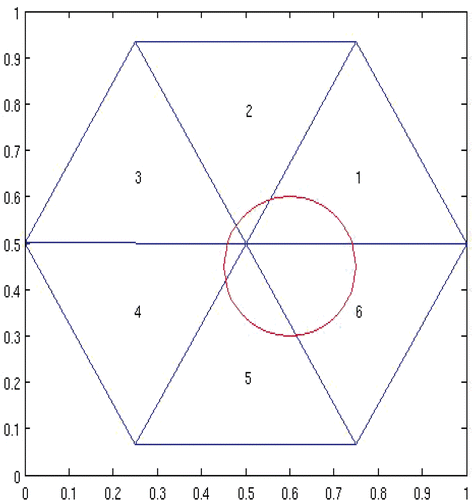
Figure 2. Permissible region Ω2 and the partition.
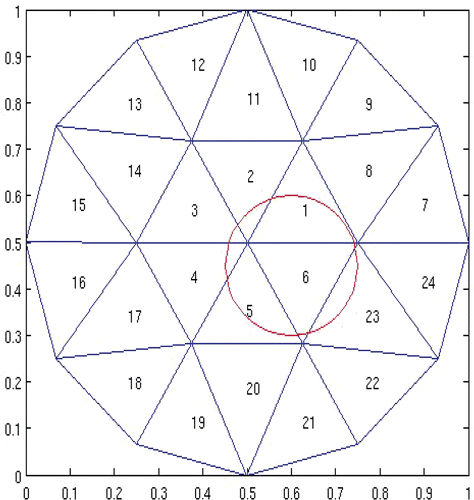
Figure 3. Permissible region Ω3 and the partition.
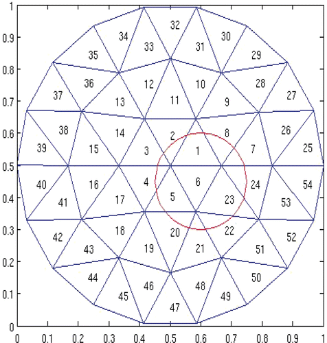
Figure 4. Permissible region Ω4 and the partition.
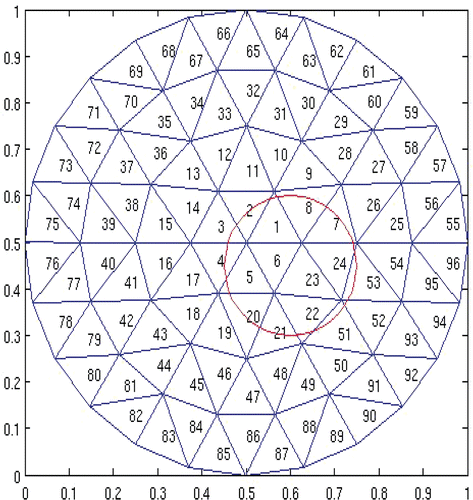
Figure 5. Permissible region Ω5 and the partition.
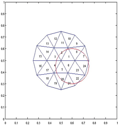
Figure 6. Permissible region Ω6 and the partition.
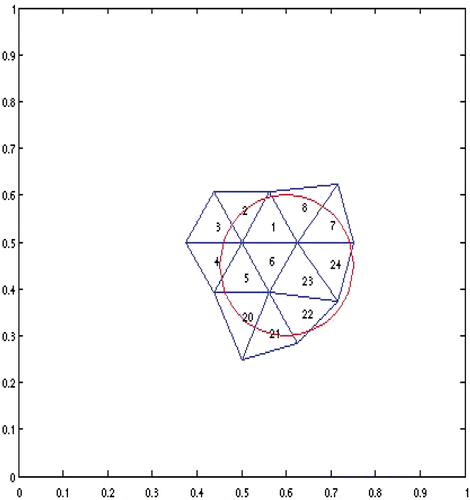
Table 1. Reconstructed source function on each element, corresponding to Figure 1.
Table 2. Reconstructed source power and center, corresponding to Figure 1.
Table 3. Reconstructed source function on each element, corresponding to Figure 2.
Table 4. Reconstructed source power and center, corresponding to Figure 2.
Table 5. Reconstructed source function on each element, corresponding to Figure 3.
Table 6. Reconstructed source power and center, corresponding to Figure 3.
Table 7. Reconstructed source function on each element, corresponding to Figure 4.
Table 8. Reconstructed source power and center, corresponding to Figure 4.
Table 9. Reconstructed source function on each element, corresponding to Figure 5.
Table 10. Reconstructed source power and center, corresponding to Figure 5.
Table 11. Reconstructed source function on each element, corresponding to Figure 6.
Table 12. Reconstructed source power and center, corresponding to Figure 6.
From the above numerical results, we see that to have accurate reconstruction of the light source, it is crucial to have a permissible region not too much bigger than the true source region. Among such permissible regions, the reconstruction quality is rather stable with respect to the choice of the permissible region. In BLT practice, one may try to develop a hybrid physical, chemical and biological process that allows a somewhat acceptable prediction of the permissible region. Also, the idea of multi-spectral BLT Citation13 may be worth exploring in this regard. Note that when the partition of the permissible region is reasonably fine, further refinement does not help improving the reconstruction accuracy.
Next, consider the effect of noise in the measurement (1.5) on the reconstruction quality. The ‘true’ measurement data used above are multiplied by (1 + δr) for a uniformly distributed random variable r with values in [−1, 1]. We only report reconstructed source powers and centres corresponding to the permissible region Ω5, in Tables . The results are similar to those of , with a higher level of noise leading to a bigger discrepancy in the numerical values. The reconstruction results appear quite stable with respect to the noise in the measurement data for this example. The reconstructed source function values on the elements are similar to those of , and are omitted.
Table 13. Results with permissible region Ω5, noise level δ = 1%.
Table 14. Results with permissible region Ω5, noise level δ = 5%.
Table 15. Results with permissible region Ω5, noise level δ = 10%.
Table 16. Results with permissible region Ω5, noise level δ = 20%.
Acknowledgements
The first two authors were partially supported by the Mathematical and Physical Sciences Funding Program of the University of Iawa and NSF-DMS-0602242. The third author was partially supported by the NNSFC (10771138) and E-Institute of Shanghai Municipal Education Commission (N:E03004).
References
- Thakur, M, and Lentle, BC, 2006. Report of a summit on molecular imaging, Radiology 236 (2006), pp. 753–755.
- Weissleder, R, and Ntziachristos, V, 2003. Shedding light onto live molecular targets, Nat. Med. 9 (2003), pp. 123–128.
- Jaffer, FA, and Weissleder, R, 2005. Molecular imaging in the clinical arena, JAMA 293 (2005), pp. 855–862.
- Rice and, BW, Cable, MD, and Nelson, MB, 2001. In vivo imaging of light-emitting probes, J. Biomed. Opt. 6 (2001), pp. 432–440.
- Contag, CH, and Ross, BD, 2002. It's not just about anatomy: In vivo bioluminescence imaging as an eyepiece into biology, J. Magn. Resonance Imaging 16 (2002), pp. 378–387.
- Ray, P, Wu, AM, and Gambhir, SS, 2003. Optical bioluminescence and positron emission tomography imaging of a novel fusion reporter gene in tumor xenografts of living mice, Cancer Res. 63 (2003), pp. 1160–1165.
- Ntziachristos, V, Ripoll, J, Wang, LV, and Weissleder, R, 2005. Looking and listening to light: The evolution of whole-body photonic imaging, Nat. Biotechnol. 23 (2005), pp. 313–320.
- Wang, G, Hoffman, EA, McLennan, G, Wang, LV, Suter, M, and Meinel, J, 2003. Development of the first bioluminescent CT scanner, Radiology 229 (P) (2003), p. 566.
- Henyey, L, and Greenstein, J, 1941. Diffuse radiation in the galaxy, Astrophysi. J. 93 (1941), pp. 70–83.
- Natterer, F, and Wübbeling, F, 2001. Mathematical Methods in Image Reconstruction. Philadelphia: SIAM; 2001.
- Han, W, Cong, W-X, and Wang, G, 2006. Mathematical theory and numerical analysis of bioluminescence tomography, Inverse Probl. 22 (2006), pp. 1659–1675.
- Han, W, Cong, W-X, Kazmi, K, and Wang, G, 2007. Bioluminescence tomography with optimized optical parameters, Inverse Probl. 23 (2007), pp. 1215–1228.
- Han, W, and Wang, G, 2007. Theoretical and numerical analysis on multispectral bioluminescence tomography, IMA J. Appl. Math. 72 (2007), pp. 67–85.
- Cheng, X-L, Gong, R-F, and Han, W, 2008. A new general mathematical framework for bioluminescence tomography, Comput. Methods Appli. Mech. Eng. 197 (2008), pp. 524–535.
- Han, W, Shen, H, Kazmi, K, Cong, WX, and Wang, G, 2009. Studies of a mathematical model for temperature-modulated bioluminescence tomography, Appl. Anal. 88 (2009), pp. 193–213.
- Han, W, and Wang, G, 2008. Bioluminescence tomography: Biomedical background, mathematical theory, and numerical approximation, J. Comput. Math. 26 (2008), pp. 324–335.
- Anikonov, DS, 1998. Comparison of two mathematical models in radiative transfer theory, Dokl. Math. 58 (1998), pp. 136–138.
- Bal, G, and Tamasan, A, 2007. Inverse source problems in transport equations, SIAM J. Math. Anal. 39 (2007), pp. 57–76.
- Stefanov, P, and Uhlmann, G, 2008. An inverse source problem in optical molecular imaging, Anal. PDE 1 (2008), pp. 115–126.
- Dierkes, T, Dorn, O, Natterer, F, Palamodov, V, and Sielschott, H, 2002. Fréchet derivatives for some bilinear inverse problems, SIAM J. Appl. Math. 62 (2002), pp. 2092–2113.
- Isakov, V, 2006. Inverse Problems for Partial Differential Equations, . New York: Springer; 2006.
- Banks, HT, and Kunisch, K, 1989. Estimation Techniques for Distributed Parameter Systems. Boston: Birkhäuser; 1989.
- Agoshkov, V, 1998. Boundary Value Problems for Transport Equations. Boston: Birkhäuser; 1998.
- Germogenova, TA, 1969. Generalized solutions of boundary value transport problems, USSR Math. Comput. Math. Phys. 9 (1969), pp. 605–625.
- Atkinson, K, and Han, W, 2009. "Theoretical Numerical Analysis: A Functional Analysis Framework, ". In: Texts in Applied Mathematics,, . Vol. 39. New York: Springer-Verlag; 2009.
- Ciarlet, PG, 1978. The Finite Element Method for Elliptic Problems. Amsterdam: North-Holland; 1978.
- Brenner, SC, and Scott, LR, 2008. The Mathematical Theory of Finite Element Methods, . New York: Springer; 2008.
- Atkinson, K, 1982. Numerical integration on the sphere, J. Austral. Math. Soc. (Ser. B) 23 (1982), pp. 332–347.
- Leopardi, P, 2006. A partition of the unit sphere into regions of equal area and small diameter, Electron. Trans. Numer. Anal. 25 (2006), pp. 309–327.
- Tikhonov, AN, 1963. Regularization of incorrectly posed problems, Sov. Dokl. 4 (1963), pp. 1624–1627.
- Engl, HW, Hanke, M, and Neubauer, A, 1996. Regularization of Inverse Problems. Dordrecht: Kluwer Academic Publishers; 1996.
- Lewis, EE, and Miller, WF, 1984. Computational Methods of Neutron Transport. New York: John Wiley & Sons; 1984.