Abstract
The inverse problem considered in this article is to determine the shape of a two-dimensional time-harmonic acoustic scatterer with Dirichlet boundary conditions from the knowledge of some far field patterns. Based on the optimization method due to Kirsch and Kress for the inverse scattering problem, we propose a new scheme by reformulating the cost functional via a technique of piecewise integration with respect to incident directions. Convergence analysis of this method is given. Numerical experiments show that our method accelerates the computations without losing the accuracy of the reconstructions for the full-aperture problems. The method is extended to the limited-aperture case by weighting the total fields with special factors. Numerical examples for limited-aperture problems are also presented which show that our method produces satisfactory results efficiently in the illuminated regions.
1. Introduction
The inverse scattering problem we are concerned with in this article is the problem of recovering the shape, or part of this shape, of a sound-soft obstacle from some time-harmonic incident plane acoustic waves and the far field patterns of the scattered waves. These types of inverse problems arise naturally in areas such as sonar, radar, geophysical imaging and non-destructive testing. Nevertheless, they are difficult to solve since they are inherently nonlinear and ill-posed. A number of methods have been proposed for solving the acoustic inverse obstacle scattering problem. For an overview on this inverse scattering problem we refer to Colton and Kress Citation1, Kirsch and Grinberg Citation2 and the survey papers Citation3–5.
The method we present in this article for the inverse problem can be viewed as a modification of the optimization method proposed by Kirsch and Kress Citation6,Citation7. The method of Kirsch and Kress avoids the solution of the direct scattering problem by reformulating it as a nonlinear optimization problem. A variety of numerical experiments (cf. Citation8,Citation9) illustrate that the Kirsch–Kress method yields satisfactory reconstructions. However, a drawback of the method is the increase in computing time when the number N of incident plane waves is increased. On the other hand, one needs several incident plane waves from different directions in order to achieve more accurate reconstructions. To the best of our knowledge, the only previous attempt to reduce the computational costs was made by Zinn Citation10, whose approach consists of using fewer total waves, generated by suitable superposition, instead of all the incident waves.
Our goal in this article is to develop a new method to overcome the problem of computational costs. Since the incident directions play an important role in the reconstruction, in our method the unit circle is partitioned into a number of segments according to incident directions. Then some of the integrations in the cost functional of the optimization problem are evaluated over these segments. Thus the cost functional possesses a more natural form since the integrations are evaluated over smaller subregions with respect to incident directions, and this leads to the computational savings. In addition, the accuracy of the reconstruction is improved, in particular, the non-convex and illuminated part of the target scatterer can be better approximated.
The rest of this article is organized as follows. In the next section, we introduce the inverse problem and outline the basic ideas of the optimization method due to Kirsch and Kress. In Section 3, we present the modification of Kirsch–Kress method for full-aperture problems. Section 4 is devoted to the convergence analysis of the modified method. In Section 5, the method is generalized to solve the limited-aperture problems. In Section 6, numerical results are presented to show the computational advantages provided by the proposed method as compared to that of Kirsch and Kress. Finally, some conclusions are given in Section 7.
2. The inverse scattering problem and the optimization method
Consider the scattering of a time-harmonic acoustic wave ui(x) = eikx·d with incident direction d and positive wave number k by a given impenetrable obstacle D ∈ ℝ2 embedded in a homogeneous isotropic medium. Then the direct obstacle scattering problem is to find the total field u = ui + us such that u satisfies the following Helmholtz equation
(1)
with the Dirichlet boundary condition
(2)
and the Sommerfeld radiation condition
(3)
It can be shown (cf. Citation1) that the scattered field us has the asymptotic behaviour
uniformly in all directions
, where u∞ is defined on the unit circle Ω and known as the far field pattern.
Now the inverse scattering problem is to determine ∂D, or part of ∂D, from a knowledge of the far field pattern u∞ for one or several incident plane waves. We remark that there is no announced theoretical results concerning the unique determination of a sound-soft obstacle with the far field pattern for one incident direction and one single wave number without any additional a priori information (some uniqueness results for polyhedral scatterers have been recently established by Alessandrini and Rondi Citation12, and Liu and Zou Citation11). Since the quality of the reconstruction can be improved by using more incident waves, the focus of this article is on the issues of determining ∂D with more than one incident plane wave and the corresponding far field patterns.
For the sake of simplicity, we first consider the case where we use only one single incident plane wave. The basic idea of the method is to stabilize the inverse scattering problem by reformulating it as a nonlinear optimization problem. The method is divided into two steps.
Step 1
Having mild a priori information about the unknown scatterer D, we can choose an auxiliary closed C2 curve Γ contained in D, such that k2 is not a Dirichlet eigenvalue for the negative Laplacian in the interior of Γ. Then we try to represent the scattered field as an acoustic single-layer potential
with an unknown density ϕ ∈ L2(Γ). As usual,
denotes the fundamental solution to the Helmholtz equation and
is the Hankel function of the first kind of order zero. The far field pattern of this single-layer potential has the representation
(4)
with
. Hence, given the (measured) far field pattern u∞, we have to solve the integral equation of the first kind
(5)
for the density ϕ, where the far field integral operator S∞ : L2(Γ) → L2(Ω) is defined by
(6)
The integral operator S∞ has an analytic kernel and therefore Equation (5) is severely ill-posed. For a stable numerical solution of (5), the Tikhonov regularization strategy may be adopted, i.e. we may replace (5) by
(7)
where α > 0 denotes a regularization parameter. In Equation (7) the adjoint operator
of S∞ is given by
where the overline designates the complex conjugate.
Step 2
Once we get ϕα as solution of (7), the corresponding approximation for the scattered field by the single-layer potential is obtained. Then we can seek the boundary of the scatterer D as the location of zero level curves of
in a minimum norm sense, i.e. we can choose D as the minimizer of
(8)
over some suitable class U of admissible curves Λ. Assume that ∂D is star-like and can be parametrized in the form
(9)
where r ∈ C2(Ω) is the radial function which satisfies the a priori assumption
(10)
with given constants a and b. Numerical experiments (see e.g. Citation8) indicate that in practice the constraints a and b are unnecessary for successful reconstructions. In the following, we always assume that the boundary ∂D of the unknown scatterer D is contained in the annulus with inradius a and circumradius b. Thus the set U of admissible curves may be chosen to be a compact subset (with respect to the C1,β-norm, 0 < β < 1) of the set of all star-like curves described by (9) and (10).
3. Optimization method with more than one wave
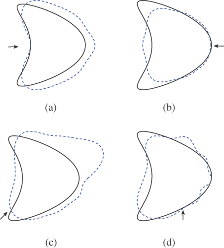
To explain the basic ideas of our method, we begin our discussion on the simplest case of reconstructing only the illuminated part of the unknown boundary ∂D with one single incident wave. shows some selected numerical results by the Kirsch–Kress method for a kite-shaped object. The solid lines give ∂D of the kite and the dashed lines give the reconstructions of ∂D. The parameters used in obtaining these figures are given in Section 6, and directions of the incident waves are indicated by the arrows in the figures. Clearly, in each figure the part of ∂D illuminated by the incident wave is well-resolved, whereas the part of ∂D in the shadow region is poorly reconstructed. Physically speaking, this is explained by the fact that the information (reflected sound energy) available from the shadow region is not enough, especially for incident plane waves with large wave numbers.
Figure 1. The effects of incident direction on the reconstruction of the kite by method 1 (α = 10−5, k = 3).
Let Λ be a curve in admissible set U, that is Λ is chosen as an approximation of the boundary curve ∂D and with the form
where r ∈ C2[0, 2π] is the radial function. In the physical optics regime, the illuminated region of the boundary Λ of a convex scatterer corresponding to the plane wave with incident direction d is defined as follows (cf. Citation1):
(11)
where ν is the outward normal to Λ. The remaining part of Λ is the shadow region
(12)
However, when we try applying (11) to the Kirsch–Kress method to retrieve only the illuminated part of ∂D, we find that an applicable parametric form of Λ− cannot be easily derived. To overcome this difficulty, we introduce the main illuminated region for a plane wave with incoming angle θ ∈ [0, 2π]:
(13)
where d = (cos θ, sin θ) denotes the incident direction. Note that Λd in (13) coincides with Λ− in (11) if Λ is chosen as a circle.
Once we have obtained the approximate scattered field with regularization parameter α via (7), we can try to find the illuminated part of ∂D as the subset of zeros of
. It seems reasonable to first try seeking the entire boundary ∂D by minimizing the defect
(14)
instead of (8). Then the illuminated region of ∂D can be recovered by suppressing the part of ∂D opposite the incident direction d.
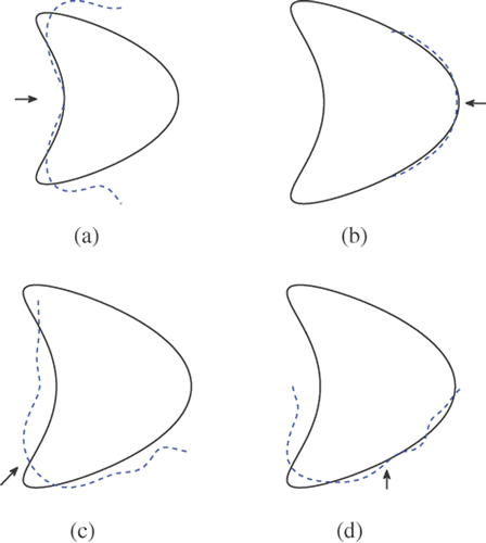
As compared to , the numerical performance of this procedure is shown in (parameters in and are the same). Clearly, the procedure produces satisfactory reconstructions for the illuminated regions.
Figure 2. The effects of incident direction on the reconstruction of the illuminated part of the kite (α = 10−5, k = 3).
To recover the entire boundary ∂D following this procedure, it is quite natural to use more plane waves incoming from distinct directions. Now we turn our attention to the case of recovering ∂D with more than one incident wave. Throughout this article, we make the general assumption that the incident plane waves with different directions uniformly distributed either over the unit circle Ω (in the full-aperture case) or over the measuring angle δ (in the limited-aperture case).
Given N(N ≥ 2) plane waves with incident angles θj ∈ [0, 2π], j = 1, … , N, we define the main illuminated region
corresponding to the j-th incident wave as follows:
(15)
for j = 1, 2, … , N, where ϑ = 2π/N denotes the aperture angle of each incident wave. Similarly, the main illuminated region
corresponding to the j-th incident wave is
(16)
for j = 1, 2, … , N. Obviously,
and
, form a non-overlapping decomposition of Λ and Ω, respectively, i.e.
Then, based on (15), we can try minimizing the following cost functional
(17)
to find the zeros of
in the least-squares sense. Here the approximated scattered fields
are given in terms of the single-layer representation of (4) and the associated densities ϕα,j are evaluated via the standard Tikhonov regularization
(18)
with a regularization parameter α > 0 and corresponding far field patterns u∞,1, u∞,2, … , u∞,N.
More precisely, by variable substitution, we seek an approximate radial function r ∈ U by minimizing
(19)
where Jr denotes the Jacobian. Here g ○ r means that the function g is evaluated on the curve which is described by r.
Remark 1
Instead of using defined in (15), one may split Λ into some overlapping main illuminated regions
satisfying
In particular, Kirsch and Kress suggest an extension of minimizing the sum
(20)
over the set U of admissible curves Citation1. However, numerical experiments we performed indicate that the computing time is correspondingly increased without accuracy improvement.
In the following, we will also refer to the Kirsch–Kress method based on (20) as method 1 and the modified method based on (17) as method 2, respectively.
4. Convergence analysis
In this section, we will investigate the convergence properties of the modified method using an analogous analysis to that of the method of Kirsch and Kress. For a detailed presentation of the convergence analysis of the Kirsch–Kress method, we refer to Citation1,Citation7.
For later use we define the acoustic single-layer operator S : L2(Γ) → L2(Λ) by
(21)
where Λ denotes a closed C2 curve containing Γ in its interior. We first describe some properties of S∞ and S (see Citation1)
Lemma 4.1
The far field integral operator S∞ and the single-layer operator S, defined by (6) and (21), respectively, are injective and have dense range provided k2 is not a Dirichlet eigenvalue for the negative Laplacian in the interior of Γ.
We are now ready to define the local single-layer operators Sj : L2(Γ) → L2(Λj) by
(22)
where Pj denotes the restriction operator, that is,
, for all f ∈ L2(Λ). Based on Lemma 4.1, we can easily deduce the following result.
Corollary 4.2
The local single-layer operators Sj, j = 1, 2, … , N, defined by (22), have dense range provided k2 is not a Dirichlet eigenvalue for the negative Laplacian in the interior of Γ.
Given N(N ≥ 2) incident waves with distinct incoming directions d1, d2, … , dN, the corresponding far field patterns are denoted by u∞,1, u∞,2, … , u∞,N. For simplicity, we shall denote
by Λj for fixed N. To analyse the convergence properties, we define the cost functional μ : (L2(Γ))N × U → ℝ by
(23)
where ϕ = (ϕ1, ϕ2, … , ϕN),
. Here α > 0 denotes the regularization parameter in (7) and γ > 0 denotes a coupling parameter which may be chosen equal to one for the full-aperture problem.
Definition 4.3
Given the incident fields , the (measured) far field patterns u∞,1, u∞,2, … , u∞,N and a regularization parameter α > 0, a curve Λ0 from the compact set U is called optimal if there exists ϕ0 ∈ (L2(Γ))N such that ϕ0 and Λ0 minimize the cost functional (23) simultaneously over all ϕ0 ∈ (L2(Γ))N and Λ ∈ U, that is we have
where
Theorem 4.4
For each α > 0 there exists an optimal curve Λ ∈ U.
Proof
Let (ϕn, Λn) be a minimizing sequence in (L2(Γ))N × U, i.e.
Since U is compact, there exists a convergent subsequence of Λn. Without loss of generality we can assume that Λn → Λ ∈ U, n → ∞. In this article, we understand convergence Λn → Λ, n → ∞, in the sense that
for the functions rn and r representing Λn and Λ.
From
and α > 0 we conclude that the sequence {ϕn} is bounded, i.e.
, for all n ∈ ℕ and some constant C. Hence, without loss of generality we can assume that {ϕn} converges weakly: ϕn⇀ϕ ∈ (L2(Γ))N, n → ∞. Since S∞ : L2(Γ) → L2(Ω) and Sj : L2(Γ) → L2(Λj) are compact, it follows that
,
as n → ∞. By Taylor's formula we have the estimation
for all
, where Ωj denotes the main illuminated region of Ω corresponding to incident direction dj. Here
where
, are the main admissible sets defined by
with incident angles θj and the aperture angle ϑ = 2π/N. Then, using the Schwarz inequality, we have
for all
. We indicate the dependence of
on n by writing
, then we have uniform convergence
. Hence, from
, we can deduce that
This implies
Since
, it follows that
then we have norm convergence
for j = 1, … , N. Finally, by continuity we get
and the proof is now complete.▪
Theorem 4.5
Let u∞,j, j = 1, 2, … , N be the exact far field patterns of a domain D such that ∂D belongs to U. Then we have convergence of the cost functional
(24)
Proof
By Lemma 4.1, given ϵj > 0, j = 1, … , N, there exists ϕj ∈ L2(Γ) such that
Hence, we have
where ∂Dj denotes the main illuminated region of ∂D corresponding to incident direction dj. Since the far field pattern of a radiating solution of the Helmholtz equation depends continuously on the boundary data (cf. Citation1), we can estimate
for some constant C. Here
denotes the exact scattered fields corresponding to
. From
on ∂Dj, we then deduce that
Thus, we have proved the theorem since ϵj, j = 1, 2, … , N, are arbitrary.▪
Based on Citation1, Theorem 5.22], we can get the following convergence result by slightly modifying the notations.
Theorem 4.6
Let {αn} be a null sequence and let {Λn} be a corresponding sequence of optimal curves for the regularization parameter αn. Then there exists a convergent subsequence of {Λn}. Assume that u∞,j, j = 1, 2, … , N, are the exact far field patterns of a domain D such that ∂D is contained in U. Then every limit point Λ* of {Λn} represents a curve on which the total fields vanish.
Hence, all the theoretical results of method 1 remain valid. Furthermore, the next theorem demonstrates that, under additional assumptions, the boundary of the unknown scatterer can be uniquely determined by the optimization methods (cf. Citation10).
Theorem 4.7
In addition to the assumption of Theorem 4.6, assume that D ⊂ Rb ≔ {x ∣ |x| < b}. For fixed k let Ns be the number of zeros of the Bessel functions Jl(t), 0 < t < kb, l ∈ ℕ. Then there exists a N0 ∈ ℕ, N0 ≤ Ns + 1, such that for N ≥ N0, the sequence {Λn} has exactly one limit point in Rb, which coincides with ∂D.
5. The limited-aperture problem
So far, we have considered only the idealized full-aperture problem. In this section, the method is generalized to solve the limited-aperture problem. In the full-aperture case, the far field data are known for all incident directions and for all measurement angles in [0, 2π), whereas in a limited-aperture case, the data are only available over a limited range of the angles (cf. Citation13,Citation14). The limited-aperture problem of inverse scattering theory is of practical significance, because it is impossible to measure the scattered radiation in all directions around an object in specific applications such as seismic imaging.
Let Ω′ be a closed subset of Ω, then the inverse scattering problem in this section is to recover ∂D from the knowledge of . Analogously, we defined the corresponding far field operator
by
Zinn Citation10 has extended method 1 to the limited-aperture case by evaluating Equation (18) only on Ω′ and formulating the resulting optimization problem with the following cost functional:
(25)
with some fixed parameter γ > 0.
Instead of , we propose the following cost functional
(26)
where
are the main illuminated regions defined in (15). Here the weights γj > 0 can be chosen according to incident directions dj and are possibly distinct. The reason for weighting the total fields with distinct γj is that, for each given incident plane wave
with fixed wave number k, its contribution to the reconstruction essentially relies on Ω′ and the main illuminated region
. Thus, we recommend the choice of γj, satisfying
By similar arguments used in Section 4, it can be easily verified that the convergence properties remain valid in the limited-aperture case. Finally, we also want to mention that, without full-aperture measurements, the ill-posedness of the inverse problem become more severe, which can be illustrated by the following theorem (for a proof, see Citation10).
Theorem 5.1
For the singular values μm of
where δ ∈ (0, 2π] denotes the measuring angle, we have the estimation
with a constant c > 0.
6. Numerical results
The aim of this section is to provide a comparison of the numerical performance of the two methods. We illustrate the numerical performance of the two methods by recovering two scatterers from their synthetic far field patterns. The boundaries of the scatterers, referred to as a kite and a peanut, are parametrized by
and
respectively. The far field data are obtained by solving the direct scattering problem by the classical boundary integral equation method and the integral equation of the second kind is solved numerically by the Nyström method Citation15,Citation16. Here we used a numerical quadrature rule with 64 equidistant gird points on [0, 2π]. The synthetic far field data are exact up to 10−8 relative error since the discretization errors decrease exponentially. For each incident direction di, i = 1, … , N, we have computed the far field pattern
at 32 equidistantly distributed observation points
with measuring angle δ ∈ (0, 2π].
For the inverse problem we always choose a circle centred at the origin with radius rΓ = 0.6 as internal curve Γ. We numerically approximate integrals over the unit circle Ω by the trapezoidal rule with 32 grid points. The integral over each main illuminated region , is evaluated using the trapezoidal rule with [32/N] grid points, where [32/N] denotes the integral part of 32/N. The regularization parameter α was selected by trial and error.
For the solution of the nonlinear least-squares problem we employed a Levenberg–Marquardt algorithm Citation17 with both functional value stopping criterion and successive iterate stopping criterion 10−6 (for the full-aperture problems) or 10−4 (for the limited-aperture problems). The starting surface Λ for the Levenberg–Marquardt algorithm was a parallel surface with distance 0.2 from Γ. The ansatz function r(θ) was chosen in the (2m + 1)-dimensional subspace Um ⊂ U given by trigonometric polynomials of degree less than or equal to m, i.e.
(27)
Numerical experiments in this study were performed with m = 8 (i.e. 17 Fourier coefficients in (27)).
Remark 2
Numerical tests performed with a larger m (for a given regularization parameter α) indicate that both methods are not able to capture further geometric details of the test scatterers, for example, the tips of the wings of the kite. On the other hand, for fixed m, the reconstruction results are very sensitive to α. Hence, experience reveals that the optimization methods are strongly dependent on the choice of the regularization parameter but less sensitive to the dimension for the approximation space for r(θ).
In some examples a random noise is added to the exact far field data u∞ to illustrate the stability of both methods. The noisy far field data ũ∞ take the form
where ‘rand’ gives uniformly distributed random numbers in [−1, 1] and ξ is a noise level parameter. The noise level is set equal to zero except when it is specified in some of the experiments.
Our test scatterers are contained in the circle with radius b = 2, which implies that for k = 1 just one wave suffices for the convergence of the two optimization methods towards the boundary ∂D since the first zero of the Bessel function Jl(t), l ∈ ℕ, is t0,1 ≈ 2.404. For the case k = 3 we need at most six waves. Note that the argument is only valid from the theoretical point of view due to the fact that the constraints for the radial function are not imposed in the numerical implementation of the Levenberg–Marquardt algorithm.
In the following, the number and directions of the incident waves are indicated by the arrows in the figures.
6.1. The full-aperture problems
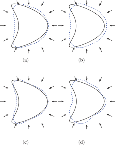
Figures show the reconstructions of the kite with N(2, 4, 6, 8, 12) incident waves, regularization parameter α(10−6, 10−7) and wave number k(1, 3).
Figure 3. Reconstructions of the kite with 2 incident waves and regularization parameter 10−6: (a) Method 1 (k = 3), (b) method 1 (k = 1), (c) method 2 (k = 3) and (d) method 2 (k = 1).
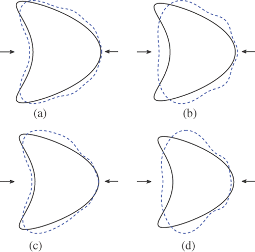
Figure 4. Reconstructions of the kite with 4 incident waves and regularization parameter 10−6: (a) Method 1 (k = 3), (b) method 1 (k = 1), (c) method 2 (k = 3) and (d) method 2 (k = 1).
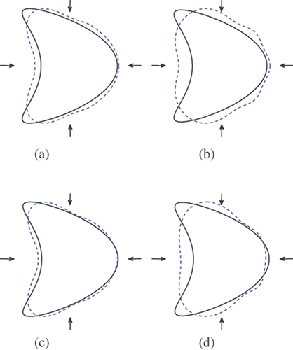
Figure 5. Reconstructions of the kite with 6 incident waves and regularization parameter 10−6: (a) Method 1 (k = 3), (b) method 1 (k = 1), (c) method 2 (k = 3) and (d) method 2 (k = 1).
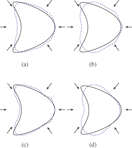
Figure 6. Reconstructions of the kite with 8 incident waves and regularization parameter 10−6: (a) Method 1 (k = 3), (b) method 1 (k = 1), (c) method 2 (k = 3) and (d) method 2 (k = 1).
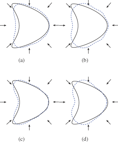
Figure 7. Reconstructions of the kite with 12 incident waves and regularization parameter 10−6 from inexact far field data (10% noise). (a) Method 1 (k = 3), (b) method 1 (k = 1), (c) method 2 (k = 3) and (d) method 2 (k = 1).
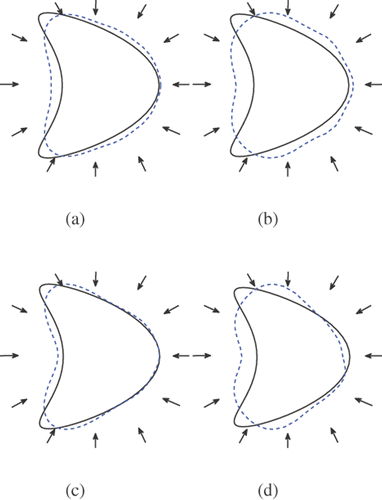
Figure 8. Reconstructions of the kite with 12 incident waves and regularization parameter 10−7 from inexact far field data (10% noise). (a) Method 1 (k = 3), (b) method 1 (k = 1), (c) method 2 (k = 3) and (d) method 2 (k = 1).
Tables compare the computing time for reconstructing the test scatterers by the methods. These tables illustrate that the increase of incident waves leads to a tremendous increase in the computing time for method 1, whereas the computing time for method 2 is roughly the same.
Table 1. Computing time for the reconstructions of the kite (s).
Table 2. Computing time for the reconstructions of the kite with noisy data (s).
Table 3. Computing time for the reconstructions of the peanut (s).
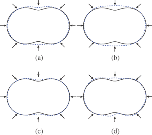
Figures show the reconstructions of the peanut with N(2, 4, 6, 8) incident waves, regularization parameter α = 10−7 and wave number k(1, 3). Figures summarize the corresponding results for reconstructing the peanut with noisy data (10% noise). Note that the non-convexity of the scatterer can be better recovered by method 2, for example, see , , and .
Figure 9. Reconstructions of the peanut with 2 incident waves and regularization parameter 10−7: (a) Method 1 (k = 3), (b) method 1 (k = 1), (c) method 2 (k = 3) and (d) method 2 (k = 1).
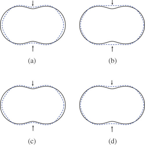
Figure 10. Reconstructions of the peanut with 4 incident waves and regularization parameter 10−7: (a) Method 1 (k = 3), (b) method 1 (k = 1), (c) method 2 (k = 3) and (d) method 2 (k = 1).
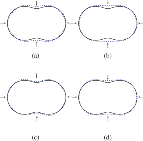
Figure 11. Reconstructions of the peanut with 6 incident waves and regularization parameter 10−7: (a) Method 1 (k = 3), (b) method 1 (k = 1), (c) method 2 (k = 3) and (d) method 2 (k = 1).
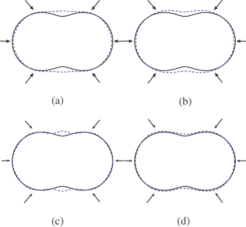
Figure 12. Reconstructions of the peanut with 8 incident waves and regularization parameter 10−7: (a) Method 1 (k = 3), (b) method 1 (k = 1), (c) method 2 (k = 3) and (d) method 2 (k = 1).
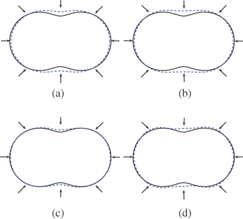
Figure 13. Reconstructions of the peanut with 2 incident waves and regularization parameter 10−7 from inexact far field data (10% noise): (a) Method 1 (k = 3), (b) method 1 (k = 1), (c) method 2 (k = 3) and (d) method 2 (k = 1).
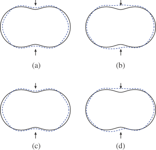
Figure 14. Reconstructions of the peanut with 4 incident waves and regularization parameter 10−7 from inexact far field data (10% noise): (a) Method 1 (k = 3), (b) method 1 (k = 1), (c) method 2 (k = 3) and (d) method 2 (k = 1).
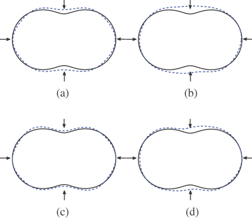
Figure 15. Reconstructions of the peanut with 6 incident waves and regularization parameter 10−7 from inexact far field data (10% noise): (a) Method 1 (k = 3), (b) method 1 (k = 1), (c) method 2 (k = 3) and (d) method 2 (k = 1).
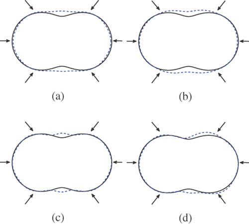
Figure 16. Reconstructions of the peanut with 8 incident waves and regularization parameter 10−7 from inexact far field data (10% noise): (a) Method 1 (k = 3), (b) method 1 (k = 1), (c) method 2 (k = 3) and (d) method 2 (k = 1).
and show that the reconstructions obtained by method 2 are more accurate than that by method 1. In these tables, the relative L2 error is defined by
(28)
where r* denotes the radial function of the exact boundary of the scatterer.
Table 4. Relative L2 errors for reconstructions of the kite (%).
Table 5. Relative L2 errors for reconstructions of the peanut (%).
6.2. The limited-aperture problems
For the limited-aperture problem, each far field pattern is only measured in the illuminated region. Given the measuring angle δ ∈ [0, 2π] and the incident angle θi ∈ [π, π + δ], each far field pattern u∞(θ; θi) is measured with observation angle θ ∈ [0, δ].
and show the reconstructions for the kite with three incident waves, regularization parameter 10−5, and measuring angles δ = 3π/2 and δ = π, respectively. and show the reconstructions for the peanut with three incident waves, regularization parameter 10−7 and measuring angles δ = 3π/2 and δ = π, respectively.
Figure 17. Reconstructions for the kite with regularization parameter 10−5 and measuring angle 3π/2: (a) Method 1 (k = 3), (b) method 1 (k = 1), (c) method 2 (k = 3) and (d) method 2 (k = 1).
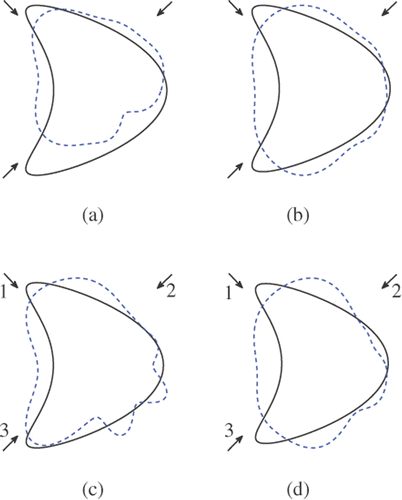
Figure 18. Reconstructions for the kite with regularization parameter 10−5 and measuring angle π: (a) Method 1 (k = 3), (b) method 1 (k = 1), (c) method 2 (k = 3) and (d) method 2 (k = 1).
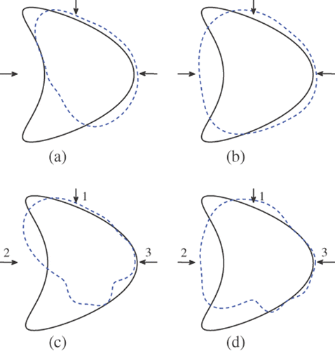
Figure 19. Reconstructions for the peanut with regularization parameter 10−7 and measuring angle 3π/2: (a) Method 1 (k = 3), (b) method 1 (k = 1), (c) method 2 (k = 3) and (d) method 2 (k = 1).
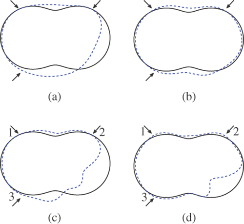
Figure 20. Reconstructions for the peanut with regularization parameter 10−7 and measuring angle π: (a) Method 1 (k = 3), (b) method 1 (k = 1), (c) method 2 (k = 3) and (d) method 2 (k = 1).
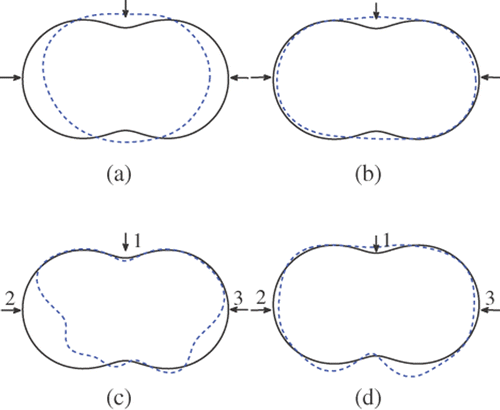
For method 2, the aperture angle ϑ in (15) for each incident direction is set equal to π/2. The incident directions dj are marked as j(j = 1, 2, 3) in the figures. In our experiments the weights γj corresponding to incident directions dj were chosen as γ1 : γ2 : γ3 = 4 : 1 : 1 except where γ1 : γ2 : γ3 = 8 : 1 : 1 was used.
The computing time for these reconstructions are given in and . The corresponding relative L2 errors are presented in Tables . The relative L2 error used in is defined by (28), whereas in and the relative error is defined by
where δ is the measuring angle and r* denotes the radial function of the exact boundary of the scatterer. These numerical results show that we can obtain better reconstructions in the illuminated regions of the peanut at lower computational costs by using method 2.
Table 6. Computing time for the reconstructions of the kite with limited angles (s).
Table 7. Computing time for the reconstructions of the peanut with limited angles (s).
Table 8. Relative L2 errors for reconstructions in the illuminated regions of the kite with limited angles (%).
Table 9. Relative L2 errors for reconstructions of the peanut with limited angles (%).
Table 10. Relative L2 errors for reconstructions in the illuminated regions of the peanut with limited angles (%).
Remark 3
To complete the discussion of numerical results, we also wish to mention some features of Zinn's method Citation10 in comparison with method 2, for details, see , and Citation10, ].
| I. | For the reconstructions of the kite with 12 incident waves and k = 1, Zinn's method and method 2 used about 18 ∼ 36% and 10 ∼ 11% of the computing time of method 1, respectively. For k = 3, Zinn's method and method 2 used about 10 ∼ 15% and 13 ∼ 16% of the computing time of method 1, respectively. | ||||
| II. | Compared with method 1, both Zinn's method and method 2 are able to retain the accuracy of the reconstructions. | ||||
| III. | To our knowledge, Zinn's method of superposition of waves has not been extended to the limited-aperture case. | ||||
7. Conclusions
In this work, we developed an efficient and robust method for solving inverse scattering problem with more than one incident wave. The method consists of coupling the optimization method due to Kirsch and Kress with a technique of piecewise integration. Numerical experiments we performed illustrate that our method turns to be less costly than that of Kirsch and Kress as the number of incident waves increases. Our future work involves the extension of the method to the three-dimensional case and also to other boundary conditions.
Acknowledgements
This work was supported by a grant from the Major State Basic Research Development Program of China (No. 2005CB321701) and by National Nature Science Foundation of China under grant nos 10971083 and 10801063. The authors thank the reviewers for their comments and suggestions.
References
- Colton, D, and Kress, R, 1998. Inverse Acoustic and Electromagnetic Scattering Theory, . Berlin: Springer-Verlag; 1998.
- Kirsch, A, and Grinberg, N, 2008. The Factorization Method for Inverse Problems. Oxford: Oxford University Press; 2008.
- Kress, R, 2007. "Uniqueness and numerical methods in inverse obstacle scattering". In: in Inverse Problems in Applied Sciences – Towards Breakthrough, Journal of Physics: Conference Series. Vol. 73. Bristol: IOP Publishing; 2007. pp. 1–16.
- Colton, D, Coyle, J, and Monk, P, 2000. Recent developments in inverse acoustic scattering theory, SIAM Rev. 42 (2000), pp. 369–414.
- Potthast, R, 2006. A survey on sampling and probe methods for inverse problems, Inverse Probl. 22 (2006), pp. 1–47.
- Kirsch, A, and Kress, R, 1987. "A numerical method for an inverse scattering problem". In: Engl, HW, and Groetsch, CW, eds. Inverse Problems. Orlando: Academic Press; 1987. pp. 279–290.
- Kirsch, A, and Kress, R, 1987. "An optimization method in inverse acoustic scattering". In: Brebbia, CA, Wendland, WC, and Kuhn, G, eds. Boundary elements IX, Fluid Flow and Potential Applications. Vol. 3. Berlin, Heidelberg, New York: Springer-Verlag; 1987. pp. 3–18.
- Kirsch, A, Kress, R, Monk, P, and Zinn, A, 1988. Two methods for solving the inverse acoustic scattering problem, Inverse Probl. 4 (1988), pp. 749–770.
- Kress, R, and Zinn, A, 1992. On the numerical solution of the three dimensional inverse obstacle scattering problem, J. Comput. Appl. Math. 42 (1992), pp. 49–61.
- Zinn, A, 1989. On an optimisation method for the full- and the limited-aperture problem in inverse acoustic scattering for a sound-soft obstacle, Inverse Probl. 5 (1989), pp. 239–253.
- Liu, HY, and Zou, J, 2006. Uniqueness in an inverse acoustic obstacle scattering problem for both sound-hard and sound-soft polyhedral scatterers, Inverse Probl. 22 (2006), pp. 515–524.
- Alessandrini, G, and Rondi, L, 2005. Determining a sound-soft polyhedral scatterer by a single far-field measurement, Proc. Am. Math. Soc. 6 (2005), pp. 1685–1691.
- Bao, G, and Liu, J, 2003. Numerical solution of inverse scattering problems with multi-experimental limited aperture data, SIAM J. Sci. Comput. 25 (2003), pp. 1102–1117.
- Ochs, RL, 1987. The limited aperture problem of inverse acoustic scattering: Dirichlet boundary conditions, SIAM J. Appl. Math. 47 (1987), pp. 1320–1341.
- Colton, D, and Kress, R, 1983. Integral Equation Methods in Scattering Theory. New York: John Wiley & Sons; 1983.
- Kress, R, 1995. Integral equation methods in inverse obstacle scattering, Eng. Anal. Bound. Elem. 15 (1995), pp. 171–179.
- Moreé, JJ, 1977. "The Levenberg–Marquardt algorithm, implementation and theory". In: Watson, GA, ed. Numerical Analysis. Berlin, Heidelberg, New York: Springer-Verlag; 1977. pp. 105–116.