Abstract
Estimation of the mechanical and geometrical parameters of thin coatings and surface layers in materials is of great practical importance in engineering and technology. Indeed, surface properties of many vital engineering components, such as turbine blades, pistons, or bearings, directly affect the longevity and safety of modern machinery. In this article, the authors present a novel inversion procedure for simultaneous determination of thickness, shear elastic constant, and density of thin coating layers in materials. The inversion procedure is based on measurements of the dispersion curve for surface acoustic waves of the Love type. The inverse problem is formulated as an optimization problem with the appropriately designed objective function, depending on the material parameters of the coating layer, ultrasonic frequency, and the experimental data, i.e. measured phase velocity of the surface Love wave. The minimization of the objective function provides three parameters of a thin layer, i.e. its thickness, shear elastic constant, and density. The proposed inverse method was checked experimentally for different layered structures, such as copper layer on steel substrate or ceramics-on-ceramics. The agreement between the results of calculations with the proposed inversion method and the experimental data was good.
1. Introduction
The mechanical properties of coatings deposited on a substrate and surface layers in graded materials are of crucial importance in the design and evaluation in modern engineering practice Citation1,Citation2. In fact, Young's modulus is the main mechanical parameter characterizing the elastic stiffness of the material. For example, it can be correlated with hardness and porosity Citation3, as well as with the wear and exploitation characteristics of the material Citation4,Citation5. Mechanical properties of thin films are also of primary importance for chip manufacturers in the electronic industry Citation6.
Traditional mechanical methods for characterization of the surface properties of materials are tedious, time consuming, and most importantly, destructive. For example, a small sample must be cut-off from the material in order for it to be examined by conventional metallurgical equipment. Employment of bulk and surface acoustic waves provide truly non-destructive tools in material characterization Citation7. Ultrasonic waves are mechanical waves, whose propagation depends on mechanical properties of the material and geometrical structures of the sample. Thus, by measuring some wave parameters, one can try to determine characteristics of the material carrying the wave Citation8,Citation9. Since ultrasonic signals can be transformed to electrical signals, using, for example, piezoelectric effect, the ultrasonic signal can be easily digitized and sent to the computer for further processing. Therefore, ultrasonic methods can be implemented on a production line for an automatic, non-destructive control of industrial processes.
An important property of all surface waves is the fact that their amplitude decays practically to zero in a few wavelength from the guiding surface. Thus, by changing wave frequency, one can probe the subsurface profiles of the material. At the beginning, thin layers in materials were investigated with Rayleigh surface waves Citation10–12, which possess at least two perpendicular components of the mechanical displacement (shear vertical (SV) and longitudinal). Due to their inherent complexity, Rayleigh surface waves are rather difficult in practical applications, since no analytical solutions for Rayleigh waves are available, even in the material with isotropic properties. By contrast, Love surface waves have only one shear horizontal (SH) component of vibration and closed-form analytical solutions for Love surface waves do exist, even in anisotropic materials. However, it should be stressed that Love surface waves exist only in materials with a surface layer which is ‘softer’ than the substrate, i.e. when phase velocity of bulk acoustic waves in the layer is lower than that in the substrate. Moreover, Love surface waves are sensitive only to shear elastic properties of the surface layer and the substrate. Nevertheless, due to its simplicity, Love surface waves are very attractive for inverse problem applications, where one must calculate the corresponding direct problem solution many times. Love surface waves were used initially in geophysics to study mechanical properties of selected geological structures Citation13,Citation14, since Love waves may accompany Rayleigh surface waves triggered by during earthquakes.
First attempts to use Love surface waves in inverse problems involved one-parameter inverse methods, which enabled the calculation of only one surface layer parameter, such as the thickness of the layer or its one elastic constant Citation9. The parameter of the surface layer was deduced from measured dispersion curve for Love waves (wave velocity as a function of frequency). In this article, the authors propose a novel inverse method for simultaneous determination of three surface layer parameters, i.e. its thickness, shear elastic constant, and density. The following layered structures were studied in this article:
| • | thin ceramic layer on a ceramic substrate | ||||
| • | thin copper layer deposited electrolytically on a steel substrate. | ||||
Calculation of Love wave parameters (e.g., phase velocity, distribution of the wave amplitude with depth) for known a priori values of material parameters of the layer and substrate constitutes the direct problem. In this study, the direct problem was formulated and solved.
The inverse problem constitutes determination of unknown material parameters from the measured dispersion curves (phase velocity as a function of frequency) for Love waves. To solve the inverse problem, one has to perform the following steps:
| • | solve direct problem | ||||
| • | determine experimentally dispersion curves | ||||
| • | solve inverse problem. | ||||
In this article, the inverse problem was formulated and solved as an optimization problem. The objective function depending on the material parameters of the structure, frequency and experimental data (dispersion curves of the surface wave) was developed. The dispersion curves were measured in the computerized measuring set-up. Making use of the optimization methods, a minimum of the objective function was determined. This enabled the determination of the unknown mechanical parameters such as shear elastic coefficients and thickness of thin coating films. The elastic and geometrical parameters of thin films obtained from the inverse method were used as input data in the calculations of the direct problem. The dispersion curves resulting from the direct problem were compared with those measured experimentally. Good conformity between theoretical and experimental dispersion curves has been stated. This may justify the correctness of the inverse problem solution.
2. Direct Sturm–Liouville problem
Calculation of the dispersion curves and amplitude of a surface wave for the given values of elastic parameters of the surface layer and substrate forms a direct problem. The direct problem (direct Sturm–Liouville problem) describes the propagation of the Love wave in the layered media.
2.1. Love waves
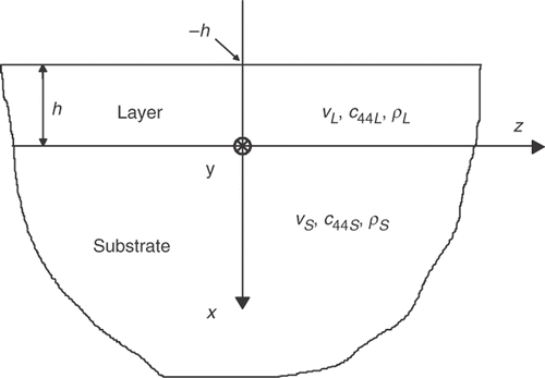
The Love wave propagates in a semi-infinite layered structure, as shown in . Here, an elastic isotropic layer is rigidly attached to an isotropic and elastic half-space. Mechanical vibrations of the SH surface wave are performed along the y-axis parallel to the propagation surface and perpendicularly to the direction of propagation z. The thickness of the layer is h. The problem considered is two-dimensional, having no variation along the y co-ordinate.
The mechanical displacement of the SH acoustic wave in the layer and substrate must satisfy the following wave equation:
(1)
where vL,S stands either for vL or vS. Here vL and vS are the velocities of bulk shear waves in the layer and substrate, respectively.
The time-harmonic mechanical displacement of the surface Love wave can be expressed as
(2)
where f (x) describes the dependence of the wave amplitude on the depth x, (
);
is the wave number; ω is the angular frequency and v is the phase velocity of the Love wave.
Analytical formulas for the mechanical displacement of the Love wave are derived by substituting Equation (2) into Equation (1) and solving the resulting equation of motion for layer and substrate region, respectively.
The mechanical displacement of the Love wave in the layer is the following:
(3)
where
and
. Here,
and
are the shear elastic constant and density of the layer material, respectively. C1 and C2 are constants.
The mechanical displacement of the Love wave in the substrate is as follows:
(4)
where
, and
. Here,
and
are the shear elastic constant and density of the substrate material, respectively. C3 and C4 are constants.
The amplitude f(x) of the surface Love wave should vanish for . At the interface (
), the continuity condition for the mechanical displacement and shear stress must be satisfied. Moreover, at the free surface (
), the shear stress is equal to zero. Therefore, the boundary conditions are in the form:
(5)
(6)
(7)
(8)
Equations (3) and (4) along with the boundary conditions (5–8) constitute the mathematical model of the Love wave propagation in a layered structure.
2.1.1. Dispersion equation
The boundary conditions (5) and (8) imply and
. By substituting (3) and (4) into the boundary conditions (6) and (7) and setting the resulting determinant equal to zero, we arrive at the following dispersion equation of the Love wave propagating in a layered half-space Citation15:
(9)
where h is the thickness of the surface layer;
is the shear elastic constant of the layer;
is the density of the layer;
is the angular frequency; v is the phase velocity of the Love wave;
is the shear elastic constant of the substrate and
is the density of the substrate.
It can be shown from Equation (9) that the phase velocity of the Love wave depends on the elastic properties of the layered structure, thickness, and frequency.
The solution of the dispersion Equation (9) results in a series of discrete values of the Love wave velocity vi, for a given value of frequency. Once the wave velocity vi is known, the corresponding distribution fi(x) of the wave amplitude with depth x can be calculated from Equations (2)–(4). A set of pairs , where vi is the surface wave velocity, and fi(x) the distribution of the wave amplitude with depth, constitutes the solution of the direct problem. The index i = 1 refers to the fundamental mode. Higher modes of Love waves are labelled with i > 1.
In this study, we have restricted our attention to the propagation of the fundamental mode of Love waves.
3. Experiment
The dispersion curves were measured in the computerized measuring set-up. In the set-up, the sending–receiving piezoelectric transducer is driven by the TB-1000 pulser–receiver computer card (Matec, USA). Love waves are excited by the plate transducer (1) attached to the waveguide face (). The sending–receiving transducer (1) is excited to shear vibrations parallel to the waveguide surface and generates impulses of the Love wave that propagate along the waveguide surface. Theoretical and experimental analysis of the generation of SH surface waves by means of a plate transducer is presented in Citation16,Citation17. The Love wave impulse generated by the transducer is reflected in multiple ways between two opposite edges of the layered waveguide (). The signals received by the transducer are amplified by the TB-1000 receiver and sent into the PDA-500 digitizer card (Signatec, USA). This card samples and digitizes the input analog signals. The accuracy of the measured velocity was estimated as 0.2%, i.e. ±6 m s−1. Measurements were carried out in the range from 0.5 to 10 MHz.
Figure 2. Waveguide (Cu on steel) of the Love wave. The shear surface wave is generated by the piezoelectric transducer plate (1) and propagates forth and back along the waveguide surface.
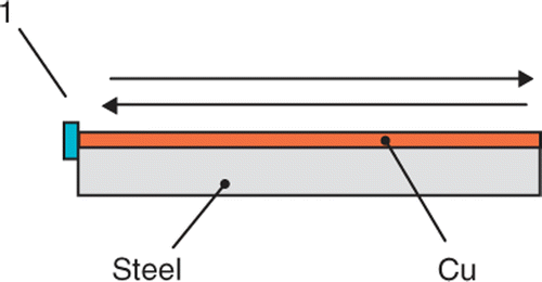
The phase velocity was determined by measuring the time of flight ‘TOF’ between two subsequent echoes of the ultrasonic surface wave travelling in the waveguide. The values of the time of flight ‘TOF’ were calculated using the cross-correlation method.
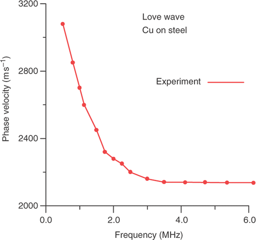
shows as an example the measured dispersion curve of the Love wave propagating in the layered structure Cu on steel from .
3.1. Investigated structures
The measurements have been carried out on the following layered structures:
| 1. | thin ceramic layer on a ceramic substrate; | ||||
| 2. | thin copper (Cu) layer deposited electrolytically on a steel substrate (). | ||||
The surface ceramic layer was a piezoelectric transducer depolarized ceramic plate glued to a piezoelectric transducer polarized ceramic substrate. The phase velocity of the bulk SH acoustic wave in the depolarized ceramics is lower than that in the polarized ceramics. This enables the propagation of Love waves in the considered layered ceramic structure.
Similarly, the phase velocity of the bulk SH acoustic wave in copper is lower than that in the steel substrate. Therefore, the Love wave can also be supported by the Cu layer deposited on the steel substrate.
4. Inverse problem
The inverse problem relies on the determination of unknown material parameters from the measured dispersion curves of SH surface waves (i.e. Love waves) propagating in the considered layered structure.
To solve the inverse problem, one has to carry out the following steps:
| 1. | solve the direct problem; | ||||
| 2. | determine experimentally the dispersion curves and | ||||
| 3. | perform the inverse procedure. | ||||
In this article, the inverse problem was formulated and solved as an optimization problem Citation18 with properly defined objective function.
4.1. Objective function
The objective function is a measure of the distance between the mathematical model of the investigated object and the real object. The objective function Π depending on the material parameters of the structure, frequency, and experimental data (phase velocity of the surface Love wave) was introduced and defined as
(10)
where Ne is the number of experimental points; ωj is the measured angular frequency; vj is the measured phase velocity; h is a guess thickness of the layer; c44L is a guess elastic constant of the coating layer;
is a guess density of the surface layer;
is the shear elastic constant of the substrate (known ‘a priori ’) and
is the density of the substrate (known ‘a priori ’).
The design variables are arguments of the objective function Π and the quantities
, and
in Equation (10) are parameters. The optimized ones are the material parameters of the layer
, whereas the material parameters of the substrate
are given ‘a priori’.
Making use of the optimization methods, a minimum of the objective function was determined. This enabled the determination of the optimum values for the unknown mechanical and geometrical parameters such as the elastic coefficient c44L, density , and thickness h of the thin coating layer. To minimize the considered objective function Π , the appropriate optimization procedures from the Mathcad® software package were employed.
The minimization problem was formulated mathematically as follows: minimize the objective function subject to linear constraints (i.e. (12), (15), (18), (21) or (24)). Employing the Mathcad package to solve the nonlinear minimization problem, the conjugate gradient method was used. In this Mathcad solving routine, guess initial values and constraints for the unknowns are required. The above-mentioned constraints reflected the real physical range of the optimized variables.
5. Determination of thin layers parameters
The minimization of the objective function subject to the given constraints results in the optimum values of unknown parameters (e.g. thickness, shear elastic constant of the surface layer).
Various numbers of parameters of the layer were extracted from the inverse method. We solved the inverse problem for three cases. In case 1, only thickness h is unknown. In case 2, we assume that the thickness h and shear elastic constant c44L are unknown, and in case 3, three parameters, i.e. the thickness h, shear elastic constant c44L and density ρL are not known.
5.1. Ceramics + ceramics structure
5.1.1. Inversion of thickness h of ceramic layer (c44L and ρL are given)
(11)
(12)
(13)
5.1.2. Inversion of thickness h and c44L of ceramic layer (ρL is given)
(14)
(15)
(16)
5.1.3. Comparison of the results obtained from the inverse method with the experiment
The exact values of the material parameters of the ceramics in both the layer and in the substrate () were determined from the geometrical and ultrasonic measurements. The thickness was measured by micrometer screw, and the velocity of bulk shear acoustic waves was measured in the layer and substrate ceramics, respectively. The density of the ceramics is known from the producer catalogue.
Table 1. Exact material properties (thickness h, shear modulus c44, and density ρ) of the investigated layered ceramics + ceramics structure.
The thickness h = 370 µm resulting from the inverse method (Equation (13)) was substituted into the dispersion equation (10) as an input data in the calculations of the direct problem. Therefore, the phase velocity of the Love wave was calculated for several values of frequency (theoretical dispersion curve). This theoretical dispersion curve was compared with the experimental dispersion curve (). Very good conformity between the theoretical and experimental dispersion curves has been observed.
Figure 4. Comparison of the experimental dispersion curve with that obtained from the inverse method (ceramics + ceramics structure).
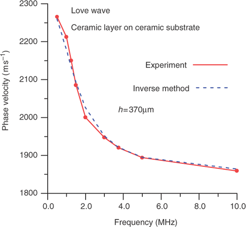
The inaccuracy when recovering the thickness of the ceramics layer may result from the technological processes used to fabricate the layered structure (surface ceramics layer on ceramics substrate). The surface ceramics layer was glued to the substrate and then polished to the final thickness. As a consequence, the real structure was instead a tri-layered structure. The third glue layer has a non-uniform thickness and undefined elastic properties. This may result in the erroneous determination of the thickness of the surface ceramics layer. This case is an example of the difficulties in modelling the real structures.
5.2. Cu on steel structure
5.2.1. Inversion of thickness h of Cu layer (c44L and ρL are given)
(17)
(18)
(19)
5.2.2. Inversion of thickness h and c44L of Cu layer (ρL is given)
(20)
(21)
(22)
5.2.3. Inversion of thickness h, c44L and ρL of Cu layer
(23)
(24)
(25)
5.2.4. Comparison of the results obtained from the inverse method with the experiment
The exact values of the material parameters of the copper layer and steel substrate () were determined from the geometrical and ultrasonic measurements. The thickness was measured using a metallographic microscope, and the velocity of bulk shear acoustic waves was measured in the copper layer and steel substrate, respectively. The densities of copper and steel are known from physical tables.
Table 2. Exact material properties (thickness h, shear modulus c44 and density ρ) of the investigated layered structure Cu on steel.
Proceeding in a similar manner as in the case of the ceramics + ceramics layered structure, we compared the experimental dispersion curve to that obtained from the direct problem and calculated for the value of the thickness h = 541 µm (). This value of the thickness has resulted from the solution of the inverse problem (Equation (19)). Very good conformity between the theoretical and experimental dispersion curves has also been stated.
Figure 5. Comparison of the experimental dispersion curve with that obtained from the inverse method (Cu + steel structure).
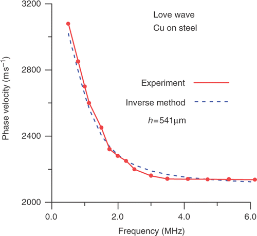
The difference between the theoretical (from the inverse method) and experimental thickness can be attributed to the properties of the technological properties of the Cu layer fabrication. The copper surface layer was deposited electrolytically on the steel substrate. From our metallographic observations it is evident that the obtained Cu surface layer has non-uniform thickness. Moreover, the structure of the surface Cu layer is porous and its contact with the steel substrate is not perfect.
6. Conclusions
A novel inverse method, employing Love surface waves for simultaneous determination of three surface layer parameters, i.e. its shear elastic constant, density and thickness, from measured dispersion curves, was developed. The proposed inverse method was then tested by ultrasonic measurements performed in selected surface structures.
Employing shear surface waves of the Love type for testing thin coating layers is more convenient than Rayleigh waves because the velocity of the Love wave depends only upon one shear elastic constant of the material. This greatly simplifies mathematical formulation of the resulting direct and inverse problems. As a consequence, the proposed inverse method provided numerical results in a few seconds on a standard personal computer (PC).
The direct problem was formulated analytically, providing a transcendental algebraic equation, which was solved numerically. Theoretical dispersion curves for the Love surface waves, propagating in the selected structures, were solutions of the direct problem.
The inverse problem was formulated as an optimization problem. Consequently, the objective function based on the dispersion equation was determined and minimized. The minimization problem was solved using the commercial Mathcad® software package.
The elastic and geometrical parameters obtained from the inverse method were used as input data in the calculations of the direct problem. Dispersion curves resulting from the direct problem were compared with those measured experimentally. Good conformity between theoretical and experimental dispersion curves has been stated. This may be evidence for the validity of the inverse method used for determining the mechanical properties of thin coating layers by means of SH surface waves of the Love type. In many papers Citation2,Citation12,Citation19, the agreement between the theoretical (resulting from the inverse method) and measured dispersion curves was treated as evidence for the correctness of the inverse method.
Many technological processes for the surface treatment (hardening, carbonizing, nitriding, implantation and diffusion) result in profiles (of the elastic properties) that vary with depth. For those types of profiles, the agreement between theoretical and experimental dispersion monotonically changing curves may provide evidence for the correctness of the inverse method.
For the structure Cu on steel the normalized distance between experimental and theoretical dispersion curves from , using the Euclidean norm (Appendix), equals 1.3%. Similarly, for the structure ceramics-on-ceramics, the normalized distance between experimental and theoretical dispersion curves from is equal to 0.6%.
More detailed analysis describing quantitatively the distance between experimental and theoretical dispersion curves will be performed by the authors in future papers.
The presented measuring method and theoretical analysis can be also extended to the identification of the mechanical properties of other classes of modern materials such as composites, intermetallics, etc.
References
- Hurley, DC, Tewary, VK, and Richards, AJ, 2001. Thin-film elastic-property measurements with laser-ultrasonic SAW spectrometry, Thin Solid Films 398–399 (2001), pp. 326–330.
- Jun, C, Zhen, Y, and Jin-quan, X, 2005. Inverse method for the determination of elastic properties of coating layers by the surface ultrasonic waves, J. Zhejiang Univ. Sci. A 6 (2005), pp. 945–949.
- Leonhardt, M, Schneider, D, Kaspar, J, and Schenk, S, 2004. Characterizing the porosity in thin titanium films by laser-acoustics, Surf. Coat. Technol. 185 (2004), pp. 292–302.
- Tsukamoto, Y, Yamaguchi, H, and Yanagisawa, M, 1988. Mechanical properties and wear characteristics of various thin films for rigid magnetic disks, IEEE Trans. Magn. 24 (1988), pp. 2644–2646.
- Schneider, D, and Schultrich, B, 1998. Elastic modulus: A suitable quantity for characterization of thin films, Surf. Coat. Technol. 98 (1998), pp. 962–970.
- Mante, PA, Robillard, JF, and Devos, A, 2008. Complete thin film mechanical characterization using picosecond ultrasonic and nanostructured transducers: Experimental demonstration on SiO, Appl. Phys. Lett. 93 (2008), pp. 071909-1–071909-3.
- Wu, TT, 1999. Elastic wave propagation and nondestructive evaluation of materials, Proc. Natl. Sci. Counc. ROC A 23 (1999), pp. 703–715.
- Kubo, S, , Inverse analyses and their applications to nondestructive evaluations, in 12th Asia-Pacific Conference on NDT, Auckland, New Zealand, 2006.
- Kiełczyński, P, and Pajewski, W, 1985. Determination of the depth of a non-homogeneous surface layer in elastic materials using shear surface acoustic waves, NDT Int. 18 (1985), pp. 25–29.
- Schneider, D, Witke, T, Schwartz, T, Schoneich, B, and Schultrich, B, 2000. Testing ultra-thin films by laser-acoustics, Surf. Coat. Technol. 126 (2000), pp. 136–141.
- Kruger, S, Levesque, D, Bescond, C, Lima, R, Maple, B, Campagne, B, Blouin, A, and Monchalin, JP, , Laser ultrasonic evaluation of thermal spray coatings, in 1st International Symposium on Laser Ultrasonics, Montreal, Canada, 16–18 July 2008.
- Wu, TT, and Liu, YH, 1999. Inverse determination of thickness and elastic properties of a bonding layer using laser-generated surface waves, Ultrasonics 37 (1999), pp. 23–30.
- Guzina, BB, and Madyarov, AI, 2005. On the spectral analysis of Love waves, Bull. Seismol. Soc. Am. 95 (2005), pp. 1150–1169.
- Bautista, EO, and Stoll, RD, 1995. Remote determination of in situ sediment parameters using Love waves, J. Acoust. Soc. Am. 98 (1995), pp. 1090–1096.
- Achenbach, JD, 1973. Wave Propagation in Elastic Solids. North Holland, Amsterdam: Elsevier; 1973.
- Viet Kinh, N, and Pajewski, W, 1980. Generation of acousto-electrical waves using a source of transverse vibrations, Arch. Acoust. 5 (1980), pp. 261–274.
- Pajewski, W, 1980. The excitation and selection of Bleustein-Gulyaev waves on piezoelectric ceramics, Acoust. Lett. 4 (1980), pp. 118–121.
- Liu, GR, and Han, X, 2003. Computational Inverse Techniques in Nondestructive Evaluation, Ch. 4. London: CRC Press; 2003.
- Penzik, S, and Zarrabi, M, 2005. A new inversion procedure for spectral analysis of surface waves using a genetic algorithm, Bull. Seismol. Soc. Am. 95 (2005), pp. 1801–1808.
Appendix
A quantitative measure of the distance between two vectors (functions) can be defined mathematically using the concept of the ‘norm’ introduced by Polish mathematician S. Banach in the first half of the twentieth century. The distance ‘’ between two vectors ‘f ’ and ‘g’ can be defined as:
, where:
is a norm, e.g., Euclidean norm. The normalized distance between two vectors ‘
’ can also be expressed in percent (%), e.g.,
.
